Pershing Guided Missile System 3/3/14 painted the Launch Pad OD

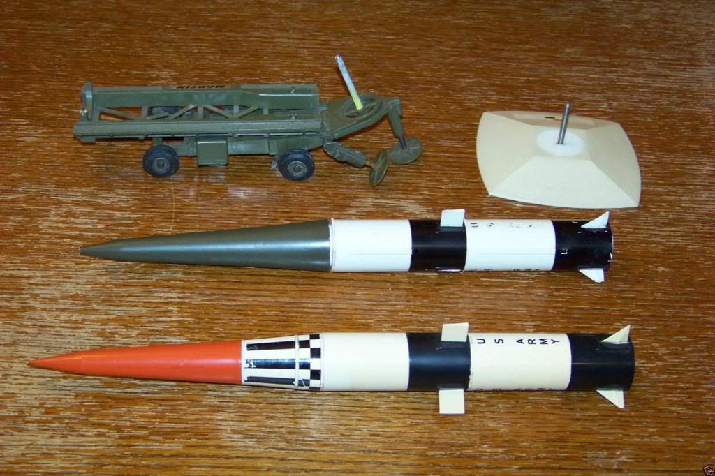
I recently acquired a Topping model of the Pershing 1 Missile and Erector - Launcher 1n 1/32 scale. I was a Pershing Missile Erector - Launcher Operator in A Battery, 3/84 Artillery In Neckarsum, Germany in 1967-68. I’ve always wanted to model my Army “gun” and this will give it to me. I have modeled an M474 vehicle which carried the missile and associated equipment.

First, some background on the Pershing 1 …

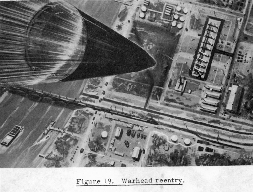
The Pershing is the U. S. Army’s longest range field artillery guided missile. In 1958, after the development of the first generation of missiles, which included the Redstone missile system, the Army determined that sufficient advances had been , made in missile technology to warrant the development of a completely new missile system to replace the Redstone. This new system, named in honor of General John J. Pershing and developed with the Martin Company as the prime contractor, utilizes many “state of the art” advances which provide greatly increased mobility and range and allow a significant reduction in size, weight and reaction time. Other outstanding improvements include ground support equipment designed for maximum tactical and strategic mobility, electronic computation of firing data, and automatic test and checkout equipment. The Pershing system also includes a specially designed communication set which is unique within the artillery and allows extremely reliable communications over great distances (99.9 percent reliability at 160 kilometers). The Pershing is normally deployed in general support of a field Army.

CHARACTERISTICS

a. The Pershing field artillery ballistic missile has the following technical characteristics:

(1) Length --34.8 feet (10.38 meters).

(2) Diameter–40 inches (1. 02 meters).

(3) Weight–IO, 275 pounds.

(4) Range–185-740 kilometers. .

(5) Propulsion–solid propellant, two-stage.

( 6) Guidance - - inertial.

(7) Warhead- -nuclear.

b. Tactical characteristics of the Pershing are as follows:

(1) The system is mounted on tracked vehicles.

(2) All elements are transportable by phase II aircraft.

(3) All elements necessary for firing are transportable by helicopter.

(4) The guidance system and firing system are immune to electronic countermeasures.

(5) The communication system allows separation up to 160 kilometers between the battery and the battalion headquarters.

GROUND SUPPORT EQUIPMENT

The Pershing system is designed to achieve minimum reaction time with maximum mobility and reliability. Mobility is provided the firing battery by mounting all Pershing-peculiar equipment, including Communication equipment, on tracked vehicles, designated the XM474E2 missile equipment carrier. The XM474E2 is a modification of the Mll3 armored personnel carrier and is specifically designed to transport the Pershing system. Mounting kits permit interchange of any of the four
Pershing loads from vehicle to vehicle without modification of the basic vehicle structure. The XM474E2 is lightweight and unarmored. It is capable of speeds up to 35 miles per hour and has a cruising range of 320 kilometers. It can travel in swamps and streams to a depth of 1. 3 meters and climb 60 percent inclines. It is powered by a 215-horsepower, V8 engine.

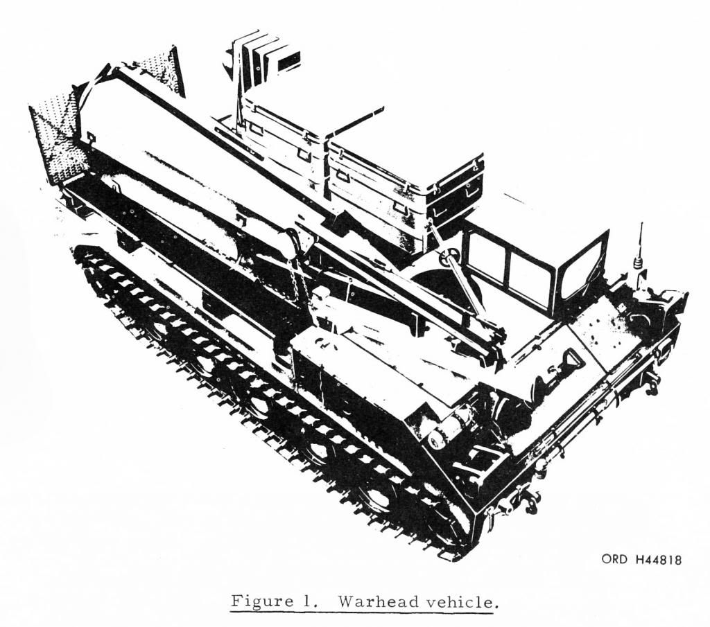
a. Warhead Vehicle. One XM474E2 carries the warhead section, two chests containing the azimuth laying equipment, and a container carrying the missile air fins. This vehicle also mounts a collapsible davit assembly which is used to mate the warhead section to the missile at the firing position.
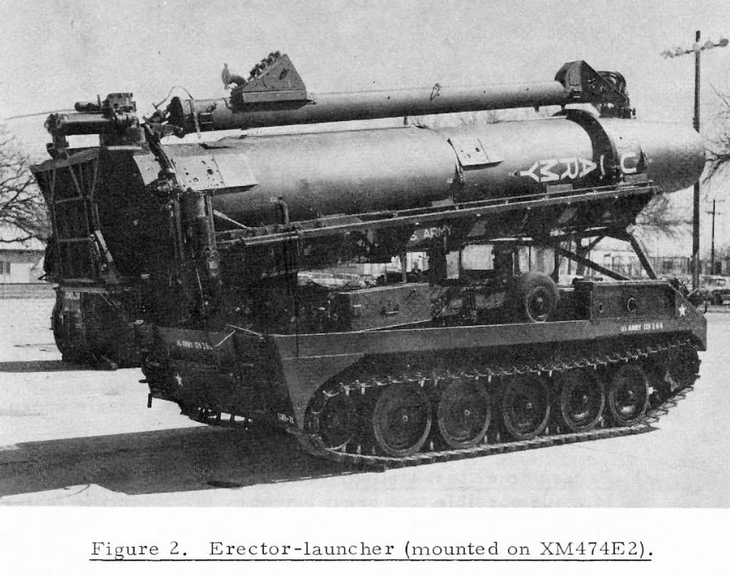
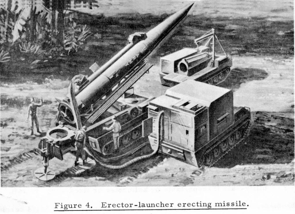
b. The Erector-Launcher.

(1) The erector-launcher is normally transported on an XM474E2 tracked vehicle; however, it may be transported by helicopter. The erector-launcher performs the following functions:

(a) Serves as a platform for assembly of the missile body sections.

(b) Supports the assembled missile, less warhead section, during transit on the XM474E2 carrier.

(c) Provides a platform for warhead mating to the missile body section, for horizontal test and checkout of the missile, and for azimuth laying operations while the

missile is horizontal. (d) Erects the missile and, if necessary, recaptures it and returns it to a horizontal position.

(e) Rotates the missile to the heading of the guidance platform after erection.

(f) Delivers electrical power, conditioned air, high-pressure air, test and checkout signals, and control signals to the missile through the cable mast.

(g) Provides a level, stable platform for firing the missile.

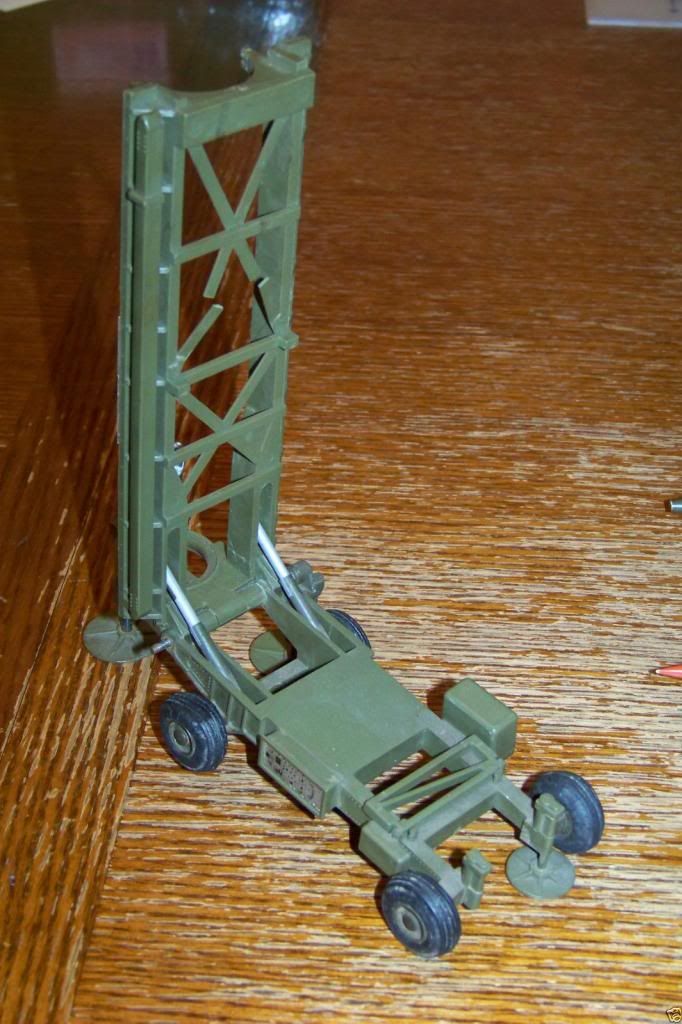
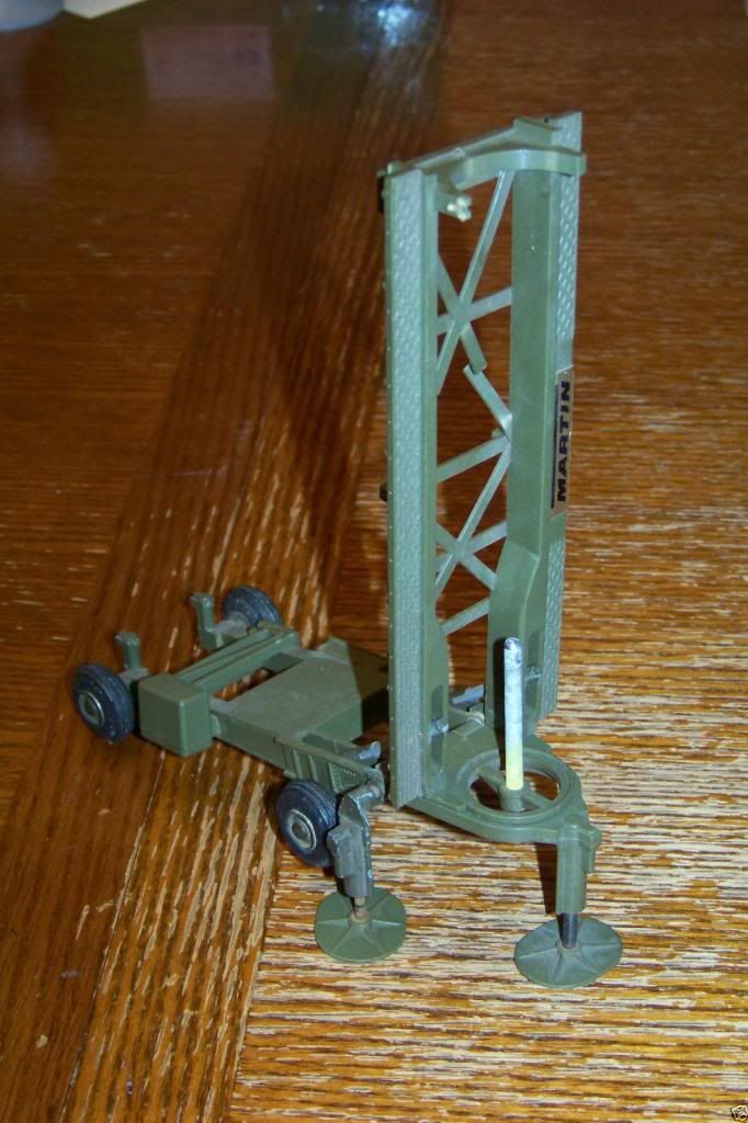
(2) The erector-launcher has four major assemblies: the transporter, the erector, the launcher, and the cable mast.

(a) Transporter. The transporter is a four-wheeled, trailer- type vehicle that can be towed or can be carried on the XM474E2 carrier. The erector and the launcher are

mounted on the transporter. The transporter furnishes electrical and mechanical control for erector and launcher functions. During the firing sequence, signals

from the programmer test station control the functions of the erector-launcher. Hand cranks can be used to manually operate equipment on the transporter when power is not available or for maintenance purposes.

(b) Erector. The erector supports the missile during assembly operations, during travel while assembled (less the warhead section), during test and checkout in the horizon-

tal position, and during erection or lowering. Ramps along the side s of the erector boom support the body section trucks and provide a working platform for personnel

during assembly operations. The erector is raised or lowered by actuators mounted on the transporter.

(c) Launcher. After the missile is erected and the erector is lowered, the launcher supports the missile and rotates it to the firing azimuth. A blast deflector under the launcher deflects the missile exhaust away from the erector-launcher. The launcher is leveled by automatically operated jacks; however, the launcher can al so be leveled manually when necessary.

(d) Cable mast. With the exception of the cable connected to the missile tail plug, all connections to the missile during the prefiring sequence are made through the cable mast. Cables conduct guidance and burst selection signals to the missile, test and checkout signals to and from the missile, and electrical power to the missile until its own power system is energized. Conditioned air and high-pressure air are routed through air hoses. The cable mast is automatically separated from the missile an instant before ignition of the first- stage motor section.

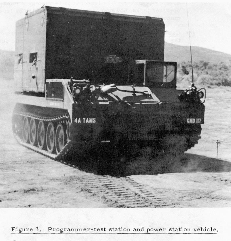
c. Programmer- Test Station and Power Station Vehicle. A third XM474E2 carries the programmer test station and power station.

(1) Power station. The power station (PS) produces both electrical and pneumatic outputs for the Pershing system. The electrical outputs are DC and AC power. The pneumatic outputs are high pressure air and conditioned air. The power outputs are used at the firing position to operate the missile and its ground support equipment and at the battery assembly area to test the.

system equipment. The power station can operate approximately 2 hours with a full tank of fuel.

(2) Programmer test station. The Pershing’s fast reaction time is made possible to a great extent by the automatic features incorporated in the programmer test station (PTS). The PTS contains completely automatic, transistorized, self-verifying equipment with a malfunction detection and isolation capability. The purpose of the PTS is to determine whether the missile is flight worthy, to compute the firing data, and to insert the required presets into the missile and energize it for flight. Within the PTS are three functional groups of equipment- -the fire data computer, the peripheral equipment, and the test and checkout equipment. The operator’s console provides countdown control and monitoring as well as control and monitoring
of the fire data computer.

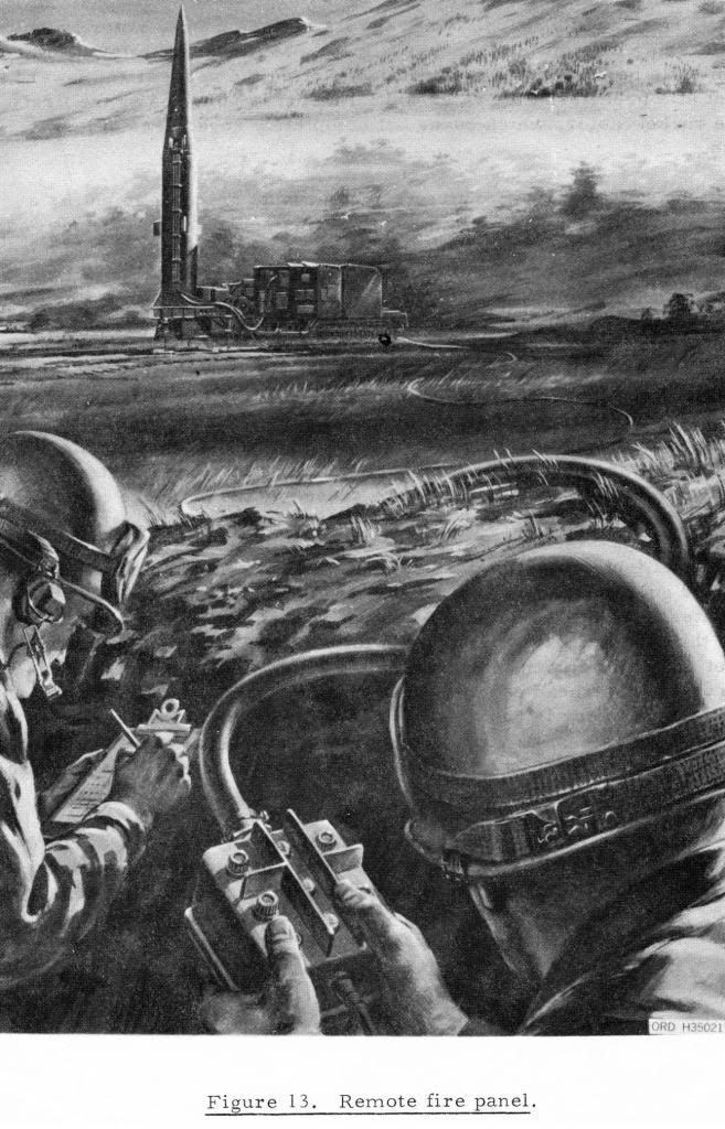
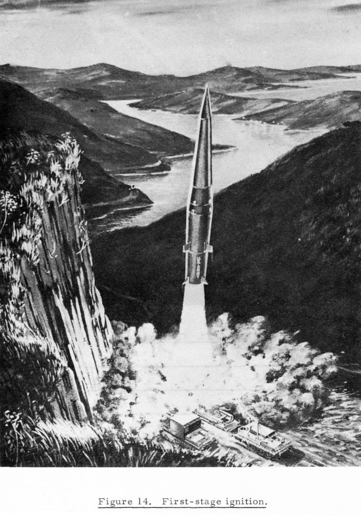
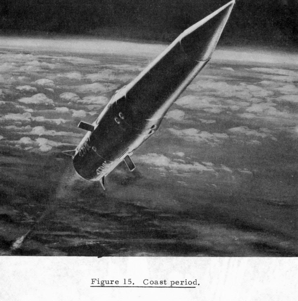
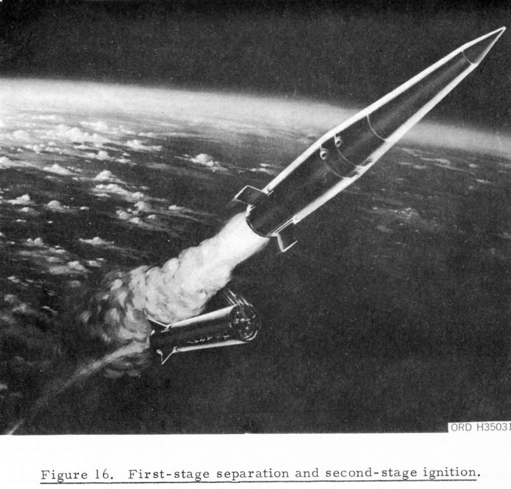
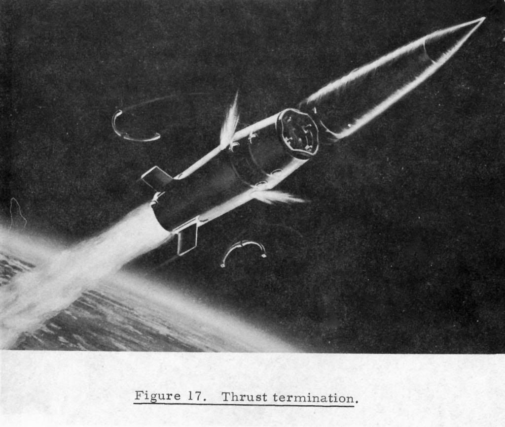
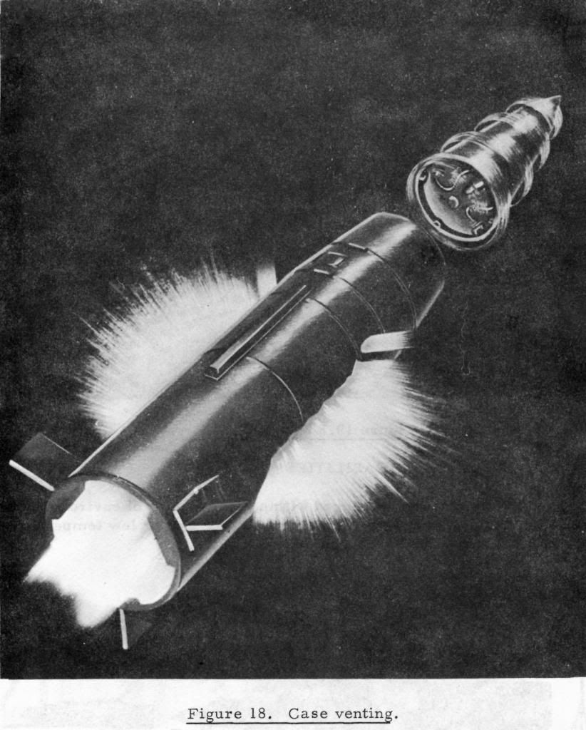
Following are drawings of the firing of a Pershing 1 Missile …

Hello!

Great info on the misille! They used to scare us with them in the Polish news when I was a kid - in the eighties. Good luck with your projects and have a nice day

Paweł

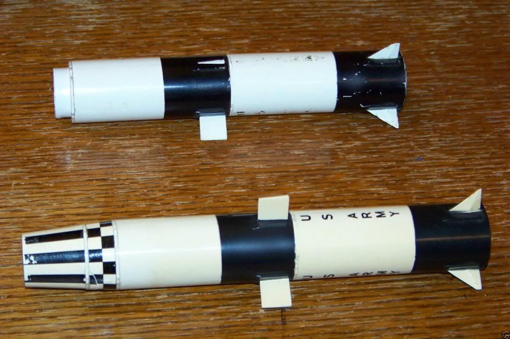
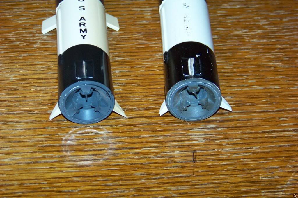
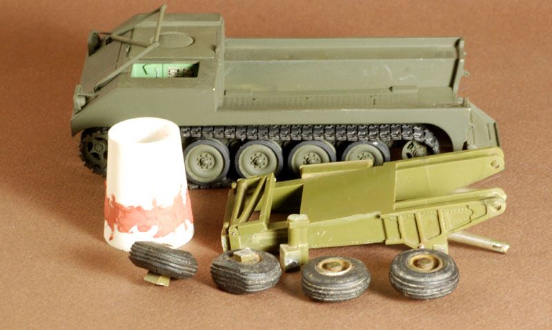
Here is the Topping model I got.

It has some problems and missing parts but enough that a little scratch building and detailing will make it work. A couple rocket fins are missing and I’ll have to cast some new ones. I got it all disassembled easily and have started to make the missing blast deflector.

I’ll get some progress photos up as soon as there’s something to show.

"Great info on the misilie! They used to scare us with them in the Polish news when I was a kid - in the eighties. Good luck with your projects and have a nice day

Paweł"

Ack … but that was the intention, I suppose. The Pershings were instrumental in removing the Russian Nuclear Missiles (and Pershings) from Europe.

Good to hear from you and thanks for the comments.

Nice stuff Foxer…love the information. It looks like the missiles and the launcher came from Martin Marritta. The missiles look exactly like the missiles from the kit I used. Where did you get your missiles??

Rounds Complete!!

“It looks like the missiles and the launcher came from Martin Marritta. The missiles look exactly like the missiles from the kit I used. Where did you get your missiles??”

Martin Marietta was the prime contractor that developed the Pershing. The 1A on wheeled vehicles that you did was still the same missile with updated ground equipment. I never saw why they got rid of the tracked vehicles, but the wheels gave better mobility on roads where most of the movement took place anyway. I’ve seen video’s of the 1A being erected and have to say it flies to vertical compared to the 1 that I worked on!

The kit I have was released by Topping, but it was developed by Martin Marietta, as was the one you did. I found the kit on ebay.

Foxer - in the end it all ended well - no nuclear tipped launches, that’s always good. As for the fins - I’d say don’t cast them, I’d recommend building them out of sheet styrene - easier to glue and probably faster to do. I see you have a lot of scratchbuilding to do, I like the idea. Good luck with your project and have a nice day

Paweł

A small post getting into the cutting and dis-assembly. The missile came apart easily after soaking in the purple pond … automotive degreaser. It seems the model was molded in styrene as regular Testors liquid glue works on it. The glued joints all pretty much came apart after a day’s dunking.

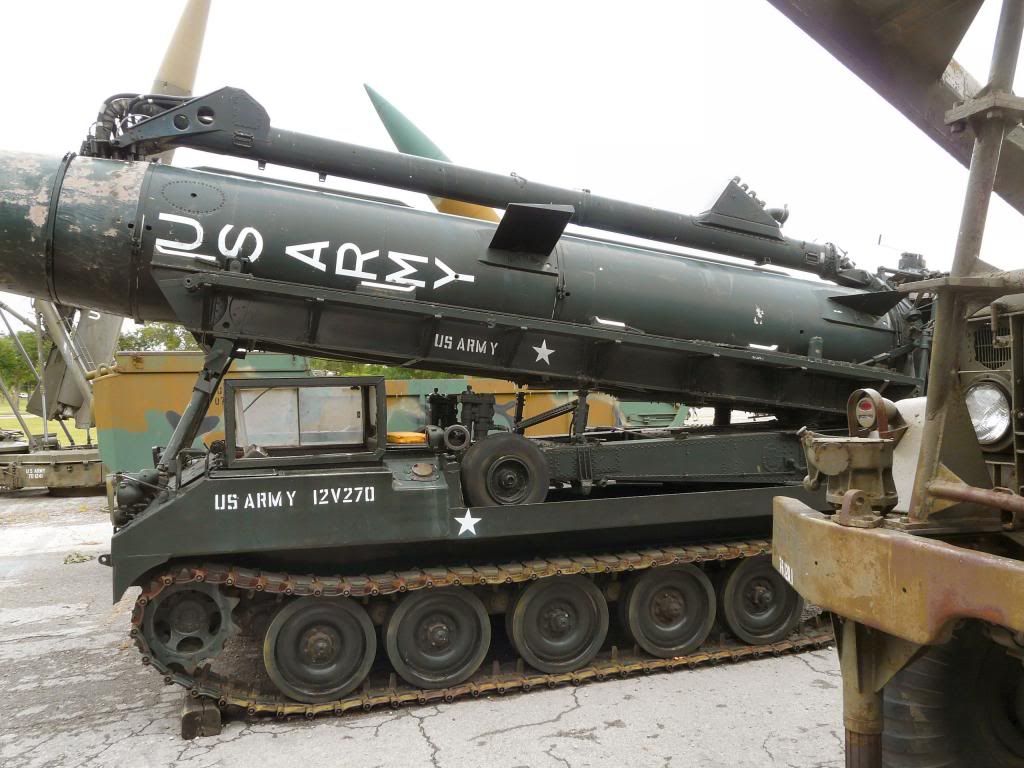
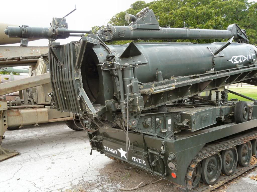
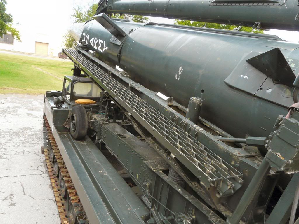
First, a few shots of a retired Erector-Launcher sitting on an X474 Missile carrier at some museum location.

I cut about a quarter inch or so off the front end of the EL frame of the 1/32 model to fit it to the 1/35 X474 I already built. I think I can use the 1/32 kit now and it will look close enough to 1/35 scale to use most of it. I will have to build the 3 Launch Pad jacks for better detail, build the blast deflector under the launch pad and replace the front wheels with something closer to scale. These are 24" diameter by 7.7" wide aircraft wheels. At worst, I have some tired from a 1/24 Mini that are close to the right size and might modify them by sanding in me Dremel.

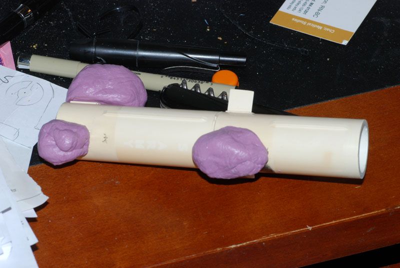
Also in the photo below, the G&C section of the missile was done in two parts with an explosive bolt ring between them. This is incorrect for the Pershing 1’s I bolted together hundreds of times. The missile photos I posted do show the G&C section with a ring in it … I believe this was a very early version and was soon replaced with a one piece G&C shell, which I am modeling. The puttied up ring in in this photo.

I also cast the fins in some silicone casting putty.

Looking good…keep it coming

Rounds Complete!!

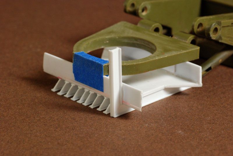
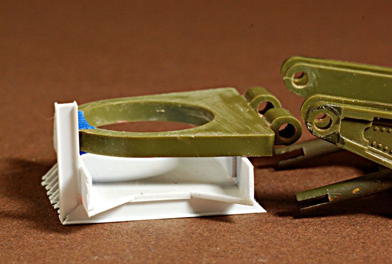
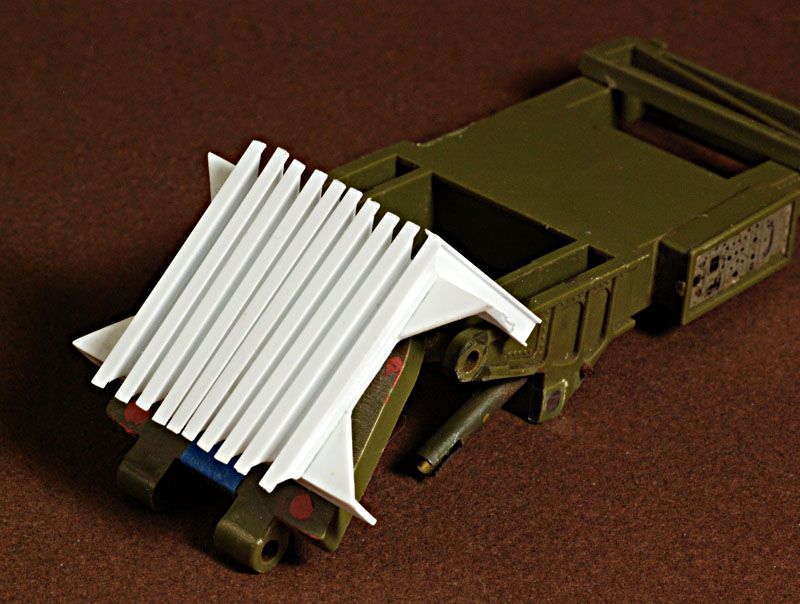
Slowly, but surely … I’ve been working on making the missing blast deflector under the launch pad. Some sheet cut to shape and ten I-beams wrap around front to back. The beams on the underside are in place but I need a trip the my LHS to get some small Channels for along the edges. Then 20 short beams for the edges. There are some shots of the deflector in the photos posted already.

Looks outstanding. Great scratch work

Rounds Complete!!

As a former member of the 56th FA Bde. (on the grunt side of the fence), I’ll be checking in on this build. Altho during my time '72-'74, they were truck/trailer mounted, the tracked version had always fascinated me but never got to see it.

Looking great so far!

Hello!

That deflector looks like a complicated part - good luck with it! Have a nice day

Paweł

This is gonna be wicked when it’s done!

Thanks for the comments … and good to see some Pershing people watching here! :slight_smile:

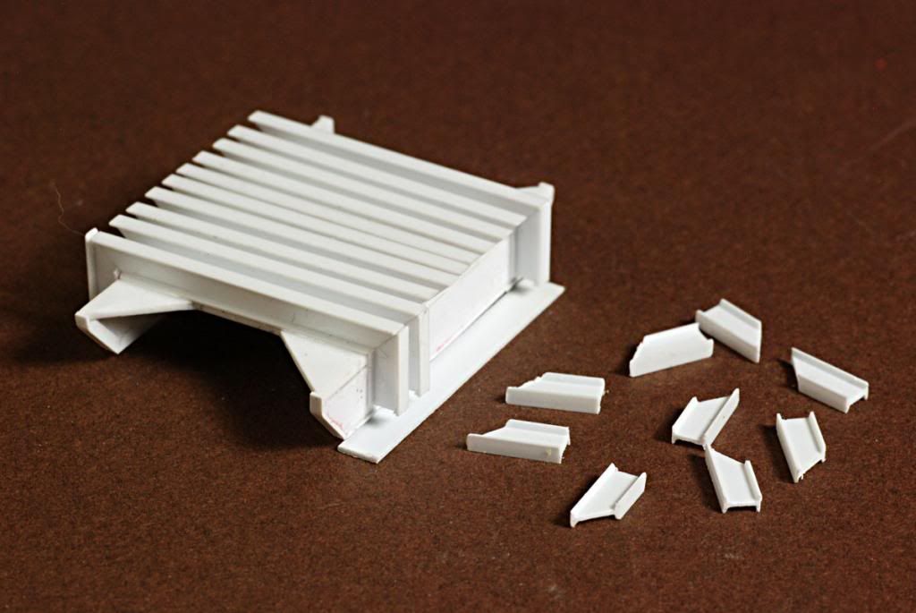
Still working on the blast deflector … there’s gonna be a lot of pieces here and it’s starting to get a bit tedious. I have to scrap all the cuts with the knife and sandpaper to clean up the saw cuts. Here’s a shot as I’m gluing the ends of the I-beams on …

See? aren’t you glad you took up modeling a subject you know so much about- all those missing details the the rest of us wouldnt know about - You get to create!

ps Great job! it looks very good.

"See? aren’t you glad you took up modeling a subject you know so much about- all those missing details the the rest of us wouldnt know about - You get to create! "

ahaha … you GOT me! Over detailing is the bane to my modeling … why I never seem to finish anything! [:S]

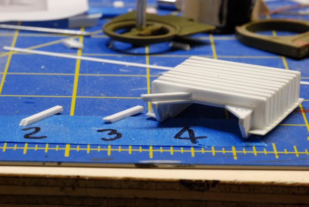
Keeping up with what I last posted I “had” to notch these braces to fit properly as structural pieces should! ( I AM a Structural Engineer). These are about the last pieces to be mounted for the blast deflector, so I feel like I’m making progress! :slight_smile: