I am going to be scratching a low wing aircraft (PT-22) that has a prominent wing fairing (fillet). Wing fairings are sort of a toroidal shape, curved in two planes with opposite sense of curvature. Anybody got good ideas of making these? I will be making the forward fuselage with formers and stringers because of the open cockpits, so cannot just carve the fillet into the fuselage block. As seperate block it would have to match fuselage section and wing airfoil, which seems like a nightmare.
That’s going to be tough, Don. It is a nightmare in full size because of the reverse curves involved. You might be able to mask the wing/fuselage joint and then lay in putty which you sculpt to the final contours. This becomes a vac-form master. If our (EAA’s) ST is anywhere similar, the bottom fairing is essentially flat, the top ones have all the curves. I use this technique with foam often on full-size to develop a pattern for forming bucks when I can’t have the airplane handy to the shop.
How do you keep the putty sticking enough to sculpt, then remove easily without it crumbling?
Epoxy putty should adhere pretty well, and set up into a solid mass that will stand some handling while you attach it to a base for the vac-form. Apoxie or Milliput both work really well for this, and you can shape them with your fingers before they set up. I guess the other option would be to incorporate the fillet into the wing itself, provided you are attaching them the way most injection-molded kits do. In any event, you have a real head-scratcher there! Is Minnesota frozen solid yet?
Yeah, I am thinking of making the wing center section seperate, so that is an idea I am considering. The hard part will be carving the fuselage section shape into the block. It is a lot easier to carve a convex shape accurately than a concave one ![]() I guess it is doable, though.
I guess it is doable, though.
Plus the fact that the fairings need to mirror each other fairly closely, it is going to consume a lot of time. Might be easier to leave the fairings off and model the attach fittings! (that’s a joke). Could you simply leave epoxy putty in place as the fillet?
Don, on RC models when I encounter this i make patterns that I can attach to the surfaces, one wing and one fuselage pattern. It’s easy to get the two sides symmetrical that way. Then I use filler of some type depending on the scale. Foam, balsa, or basswood, which I fit in sections from front to back. Then it is a matter of carving in the radii, which is easier when you can see the intersections with the wing and fuselage.
I just wish there was an easier way.
I remember a couple of decades ago, there was a product introduced that would mold very easily (they said). It was like a sheet of plastic, and you dipped it in a tray of lacquer thinner. It then would soften and could be shaped easily, but it would not dissolve completely nor break into pieces. It failed in the marketplace or somewhere. I never even saw it in my LHS. Sounds like it would be ideal for making things like fillets.
I was thinking you could make a sandwich of vertical pieces of 1/8" basswood each cut in the right section, plotted from drawings. Sort of bread and butter. But the underside is quite a bit wider than the top side no doubt.
That would be a lot of drafting and cutting. The model is going to be 1:24 scale! I guess I will get it that far, wrap wing and fuselage in saran wrap, and just try things.
Sig Manufacturing sold the sheet you are talking about, Don. I think I have a sheet of it laying around somewhere but who knows where. I think it was called Celastic.
Don would you please show what your talking about? I feel like I’m back in Emry Riddle again?
None of my shots are that great, but here are the two best.
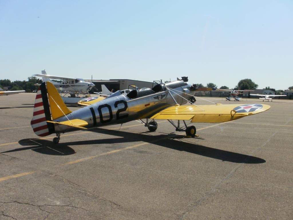
I am talking about the fairing at the intersection of the wing and fuselage. In the above picture it is pretty much in shadow. Here is another shot, closer up. The fairing can just be seen at the far left of the image.
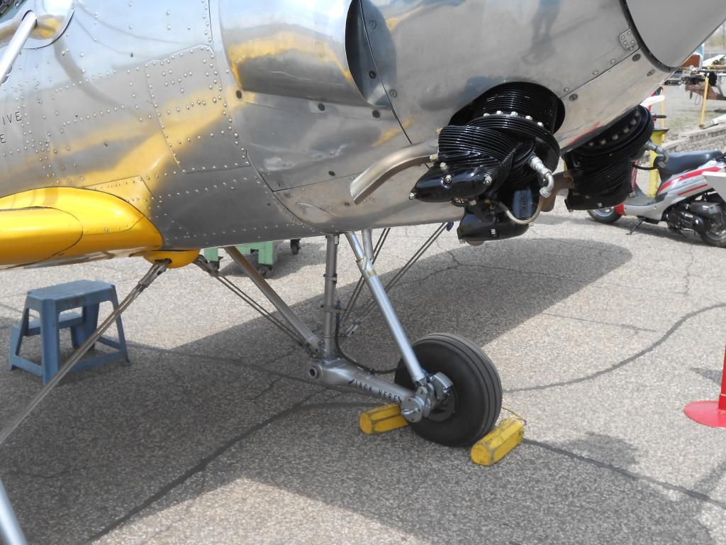
These are fine shots buddy. I know your talking about the fairing where the wing root attaches to the fuselage? Do you have a photo of your project?
DON ;
Based on your photos , why don’t you just use microbeads and resin to make the fillets . A good pass with a thumb , finger or clay shaping tool would work , I believe .
Don,
If you have any access to the original plans, I could CAD up the fairing where you could print the “templates” on your regular printer and carve them from known plastic sheet thickness. (.040" or such)
You would glue the cut pieces in a stack arrangement and fair them in using normal modeling techniques. Think of this process as a manual 3D printing technique without the printer…I’ve been doing this for years both at work and in my “builds”.
Also a good set of radius gauges (google radius gauges if you are not familiar with this tool) is a must for scratchbuilding. These tools can be expensive, but a less expensive alternative is getting a draftsmen’s radii template (google Metric Small Radius Radii Circles Circle Drawing Drafting Template Stencil) and use this tool to “drag” your fairing contours in in your putty of choice. You clean up the the template afterwards with 90% plus IPA.