Edward Hopper: House by the Railroad in 1:48 (start to finish)

As noted earlier, I did get a pretty full day in the shop. My full day starts around 1 p.m. I cleaned up the spiral stair and it was decent. There was some delamination under each step, but it wasn’t a show-stopper.

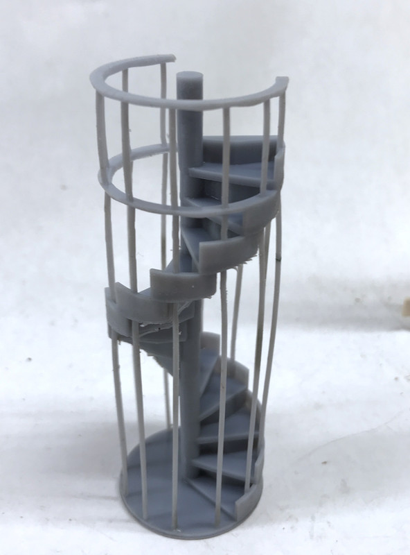
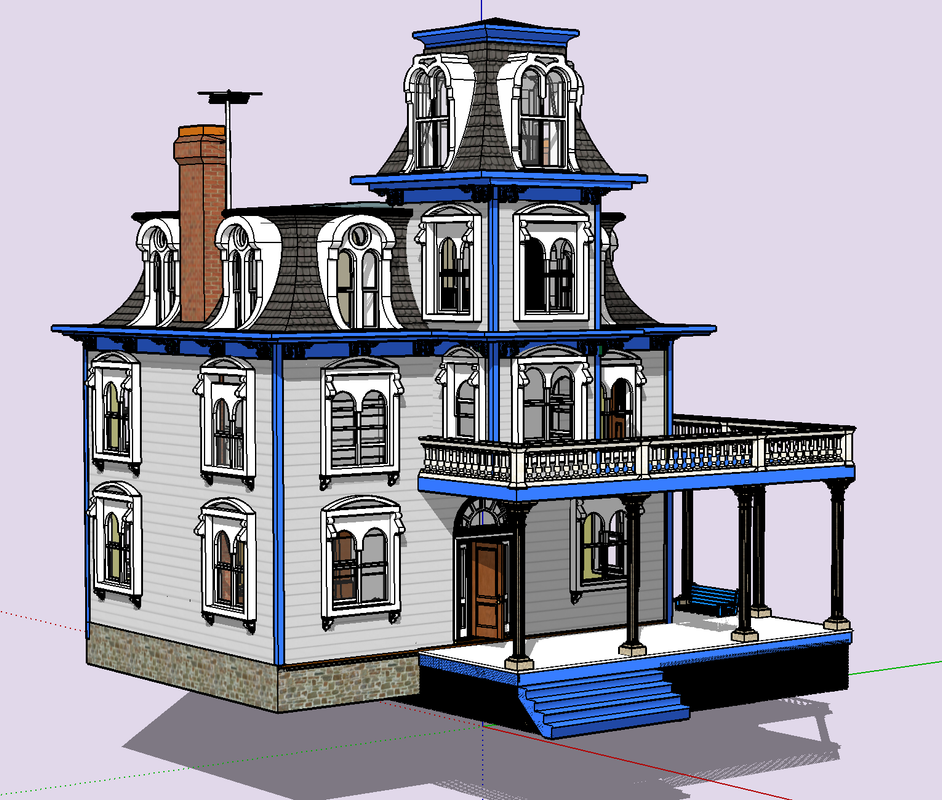
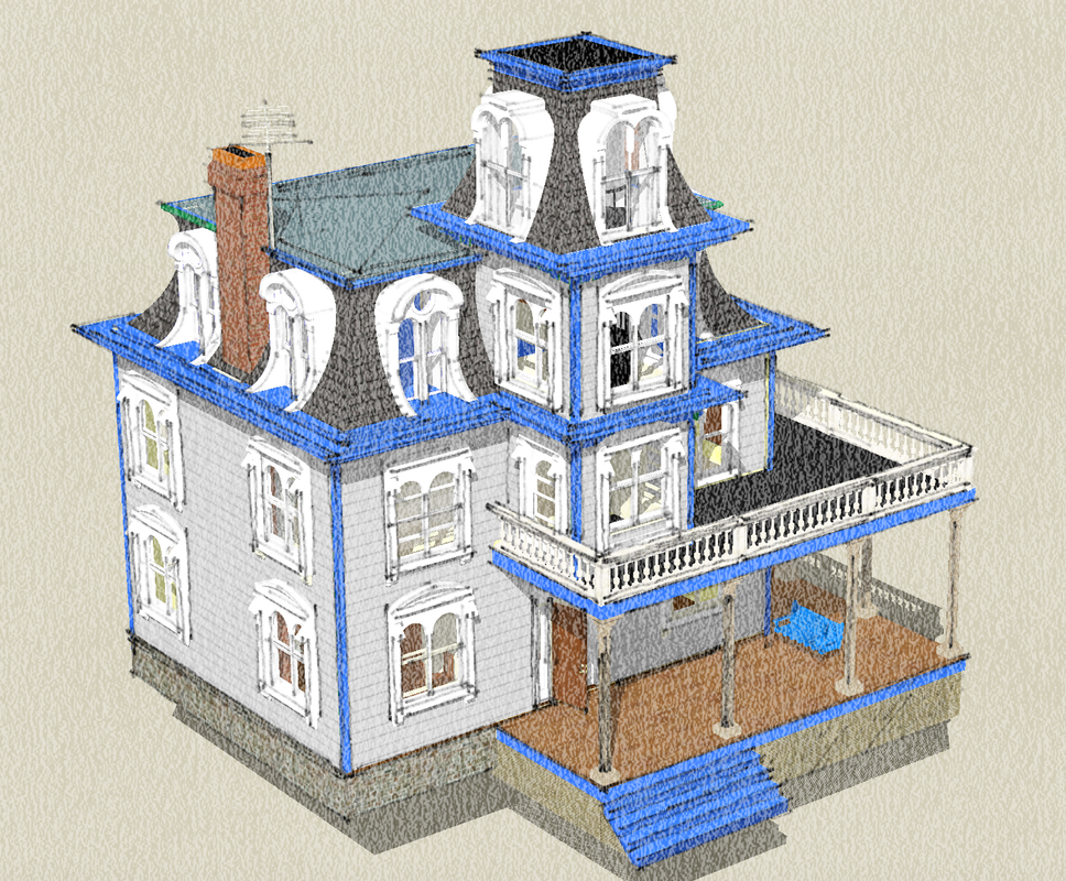
What was almost a show-stopper was my original measurements. I made it too tall by one full step. It seemed to have fit in the SketchUp model, but not in the real-world one. What to do? I thought about re-drawing it correctly and reprinting, but I first tried to do some selective surgery to remove the extra step and associated railings.

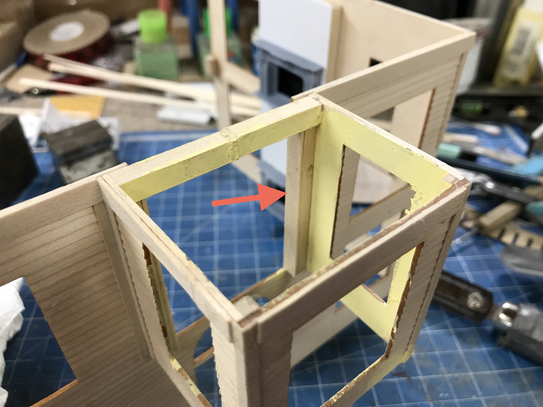
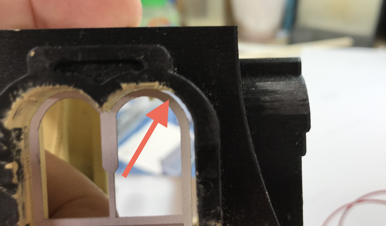
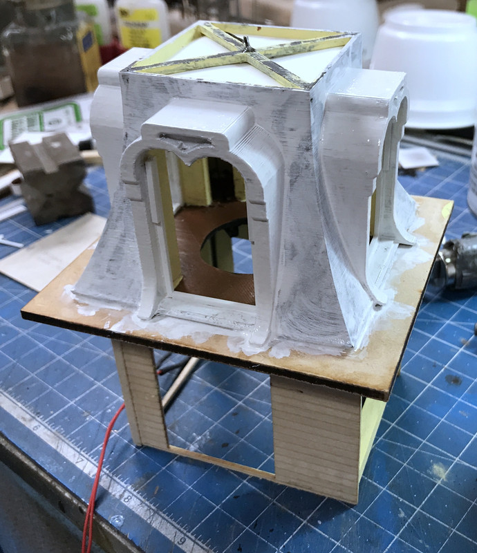
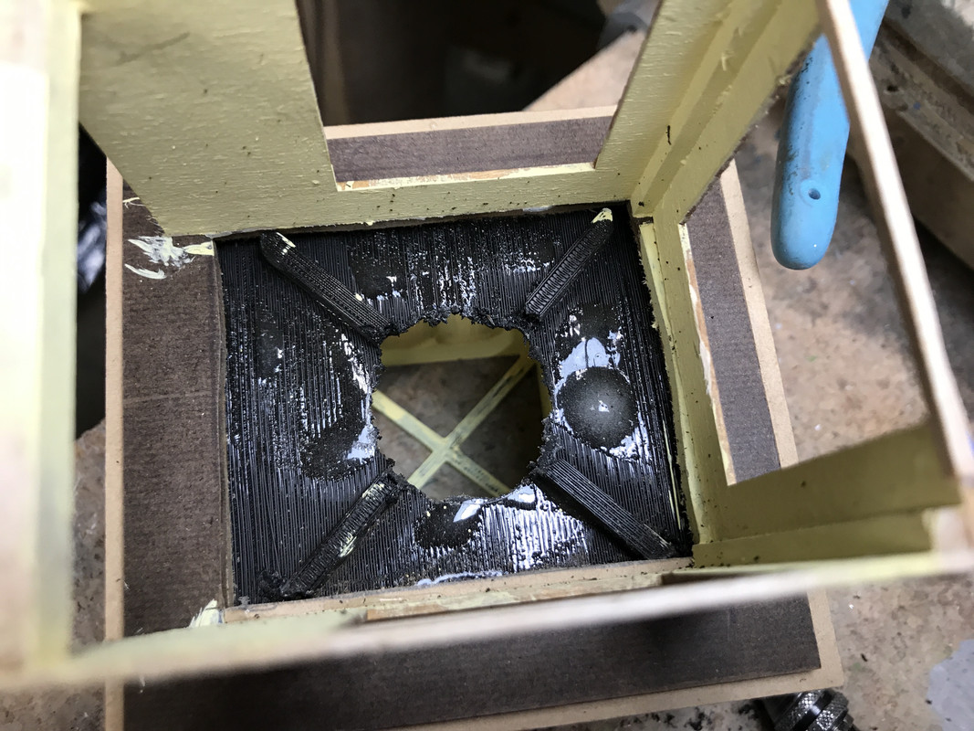
In order to actually test it I had to cut that hole in the cupola floor. I was almost ready to purchase a MicroMark powered Sword Saw to do the plunge cut. I held off and went the 1/16" carbide router route. The FDM printed PLA plastic is tough, but melts. The carbide, even at my slowest Dremel speed quickly loaded up with melted plastic. I found I could plunge the running cutter into a wooden plank and melt and fling the plastic off so I could continue cutting.

I first had to knock off the reinforcing ribs, scribe the circle and start cutting. After I opened up the rough hole I finished it with a sanding drum, again at the slowest speed.

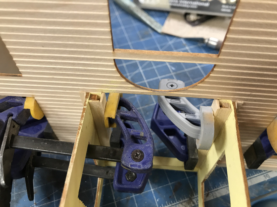
And here’s the hole opened out before sanding.

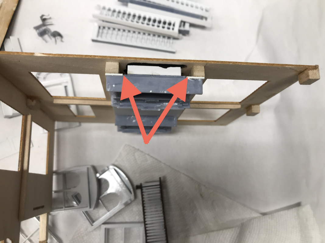
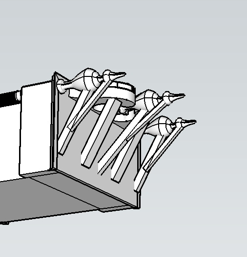
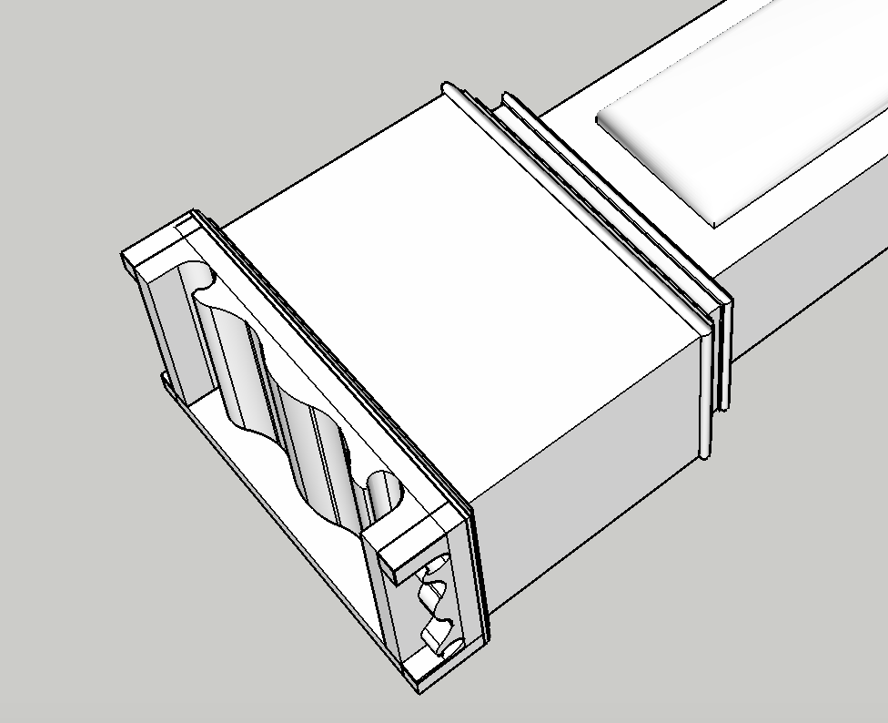
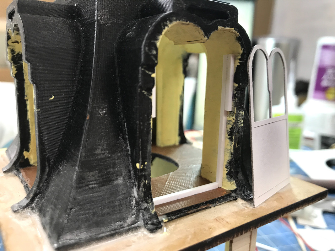
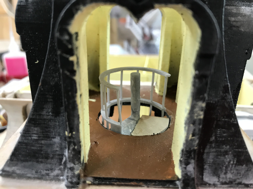
Here’s how the incorrect stair looked when installed in the opening.

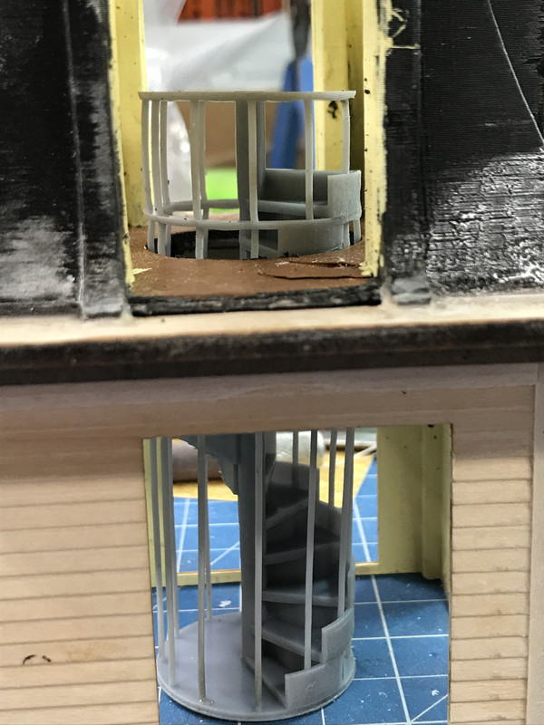
I used the Dremel with a diamond coated conical burr to cut away the extra step. I cut the upper railing and a few of the vertical rods. I then had to add a landing so you could step off the stairs onto the floor. I needed to add a little extension on the landing to push the now-unsupported top rail which was springing inwards.

With spiral staircase properly fitted I airbrushed it with semi-gloss black.

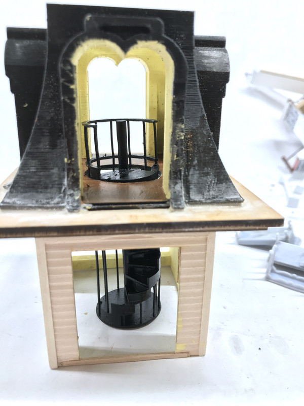
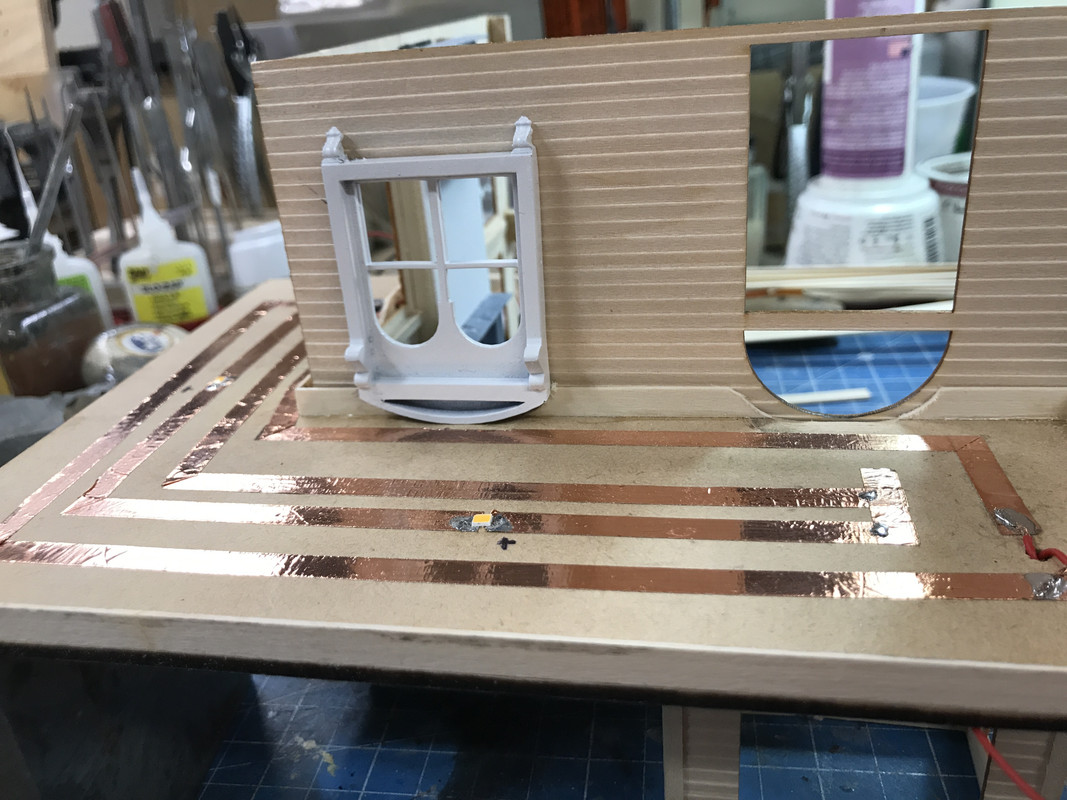
The spiral is not finally glued yet. There was more to do. I had to cut the same opening in the ceiling liner of the turret room. I also installed the single grain-of-wheat incandescent bulb in the turret ceiling. I drilled a small hole in the cross-bracing in the cupola top and a similar hole in the ceiling liner. I then used Bondic to glue the bulb into the hole. I’m running the wires down the front corner of the turret room so it will be difficult to view. These wires will be tied into the hot and ground before the CL2s in the 2nd floor wiring.

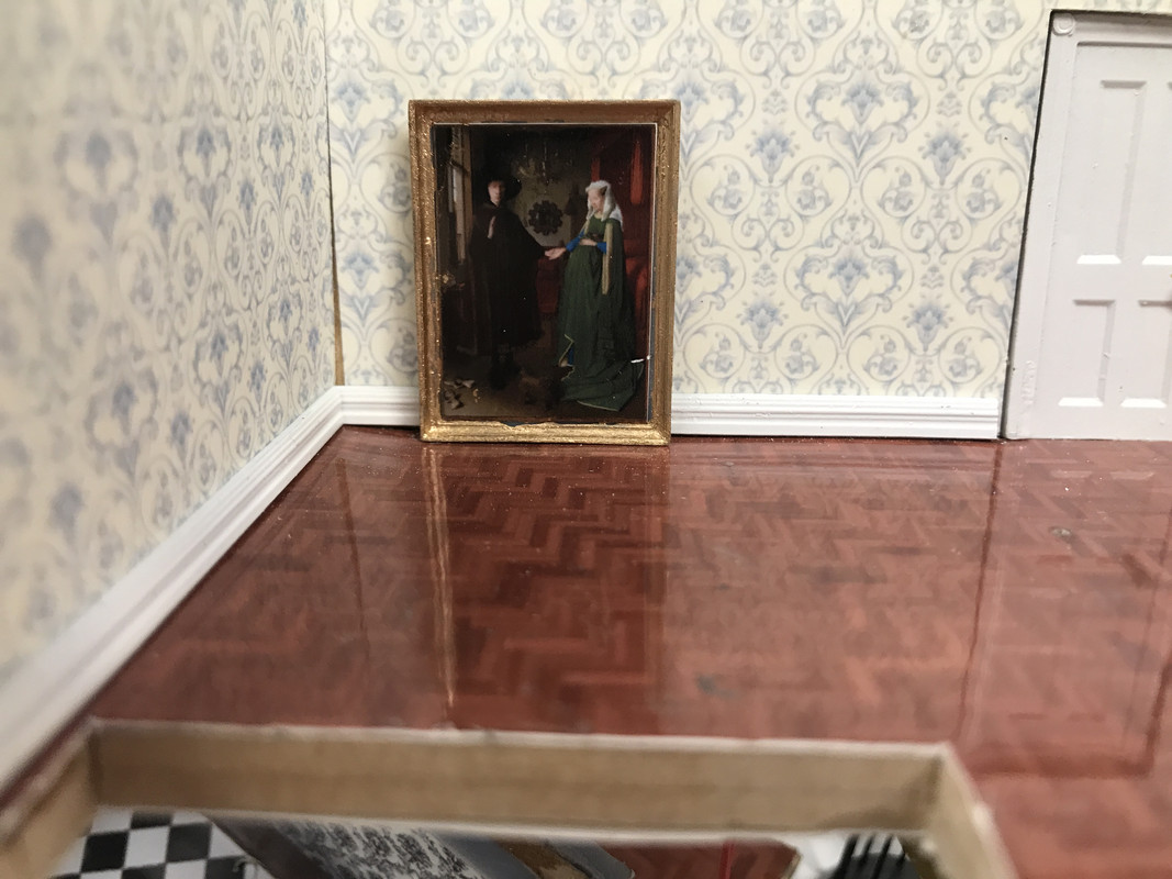
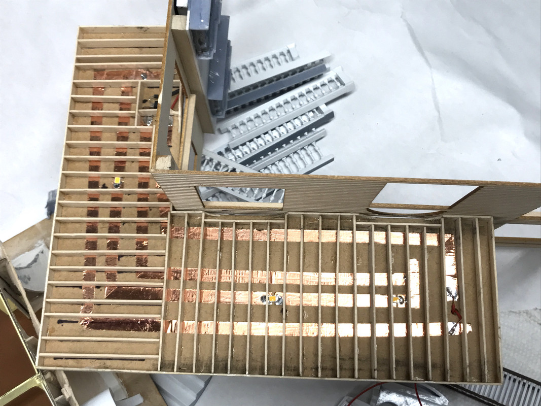
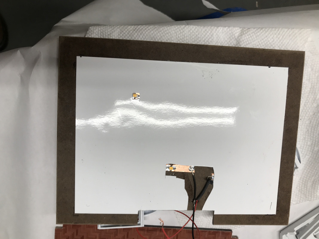
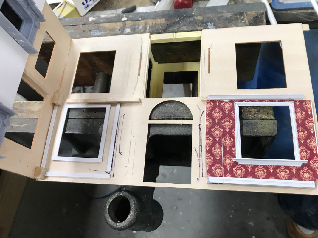
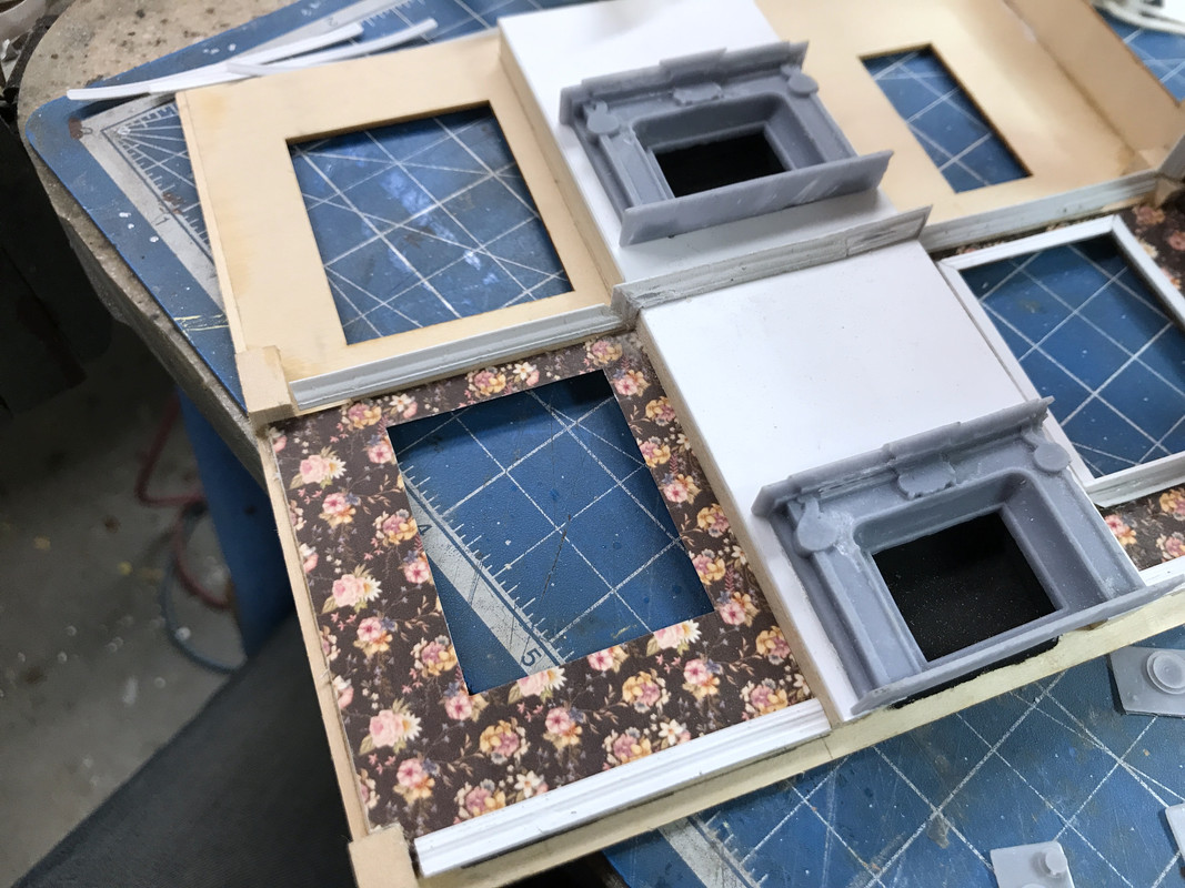
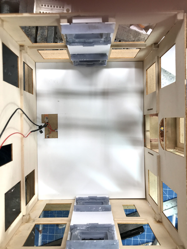
Speaking of the second floor, I got the white photo paper ceiling installed there also. I drilled holes through the back center rooms of both second and first floors to take the wiring down to the basement. I also opened the first floor in the entry closet space to bring those wires to the basement also. The open space with the wiring is not visible because these back rooms have no windows. There will be an exterior door, but its windows are too small for effective viewing.

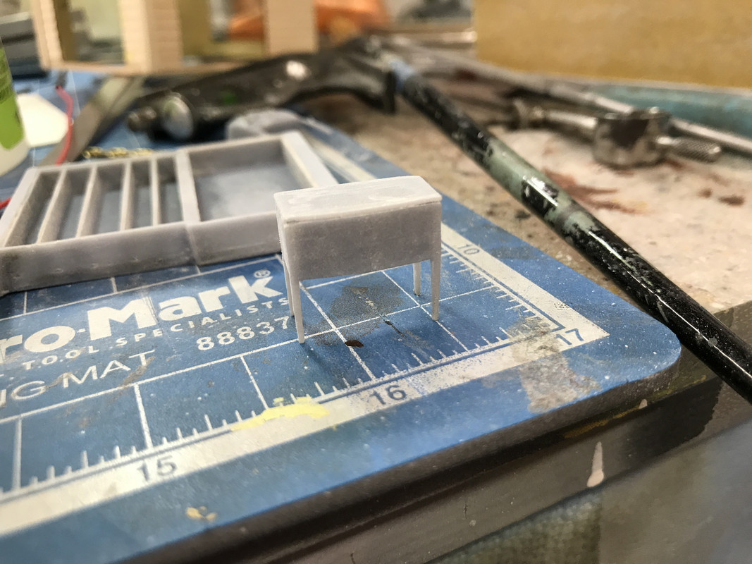
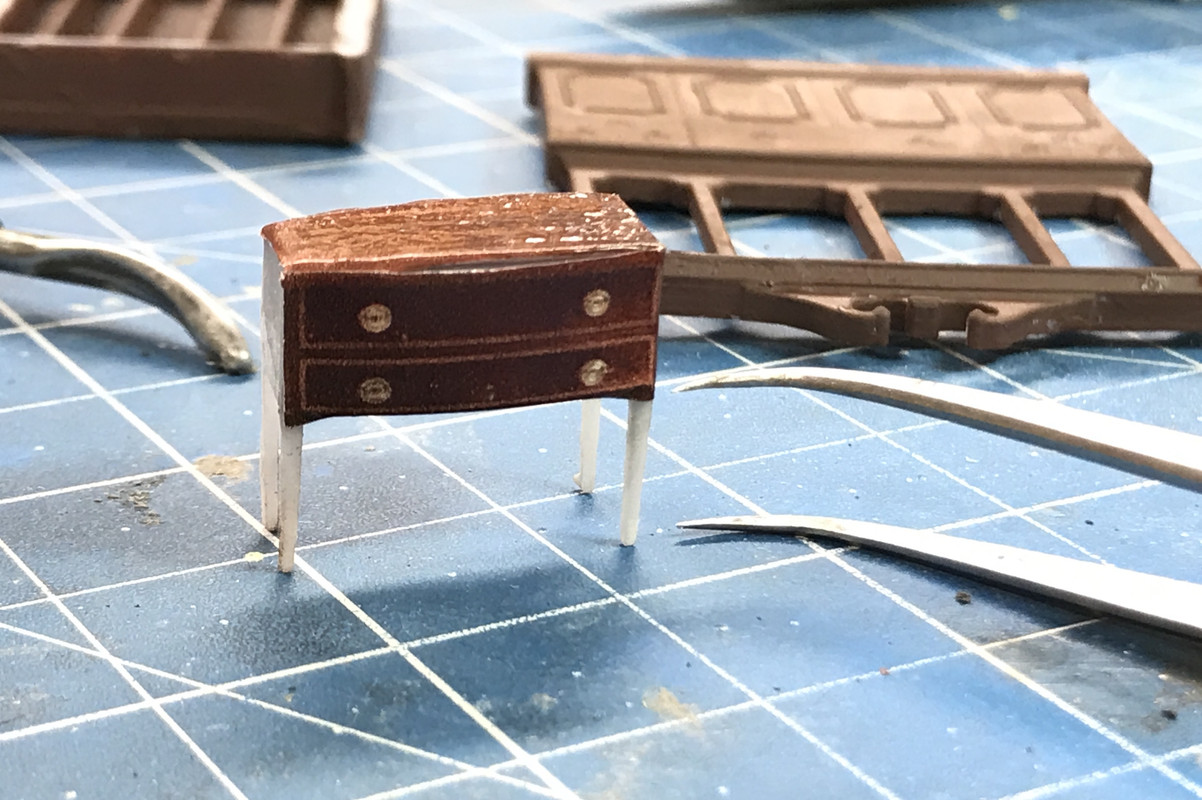
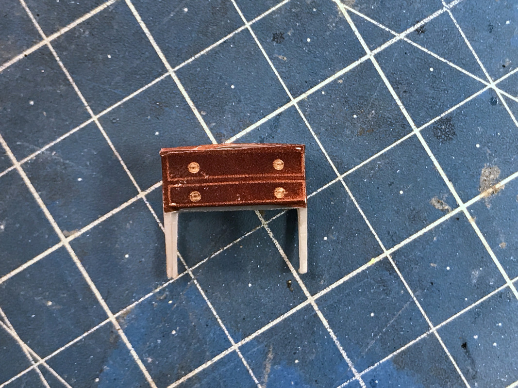
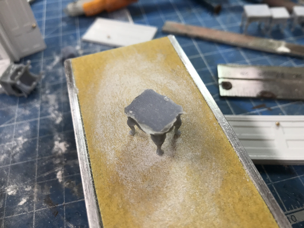
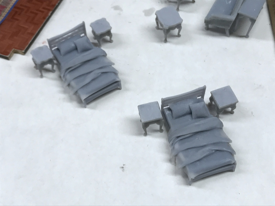
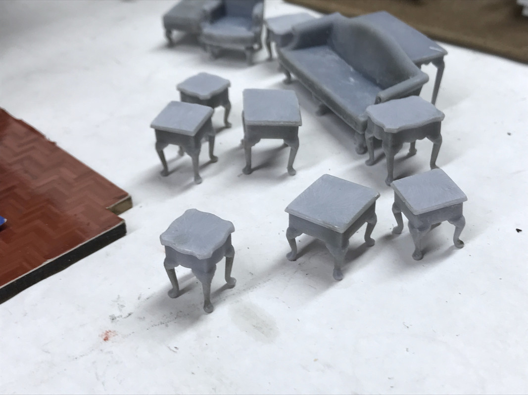
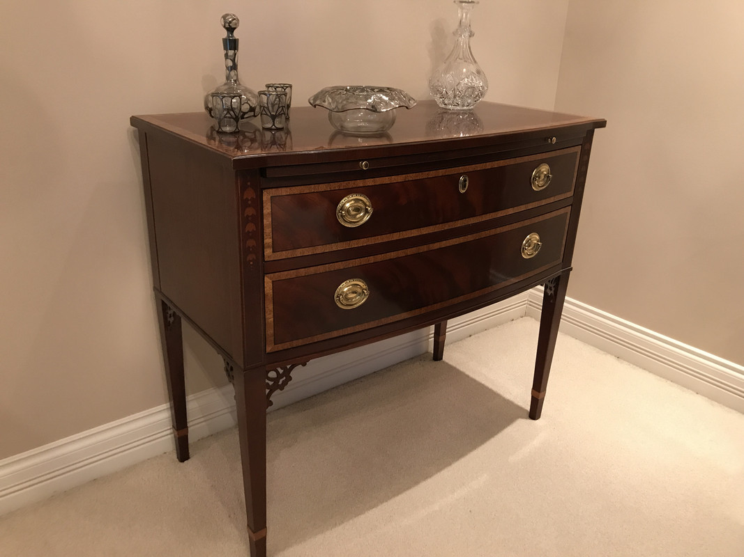
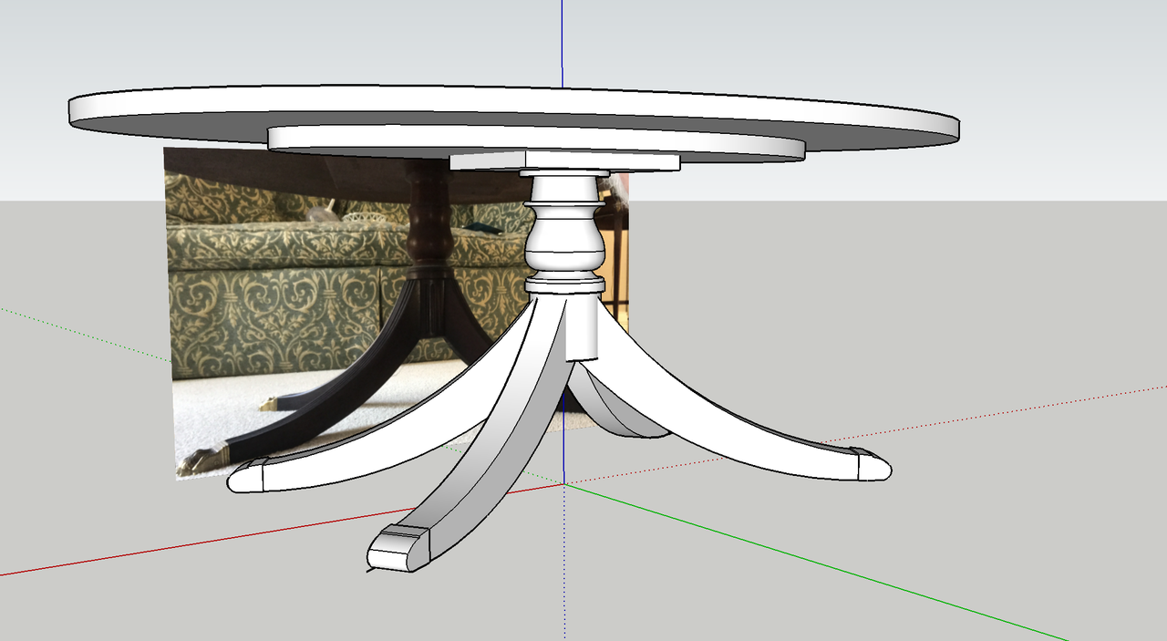
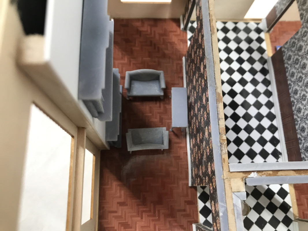
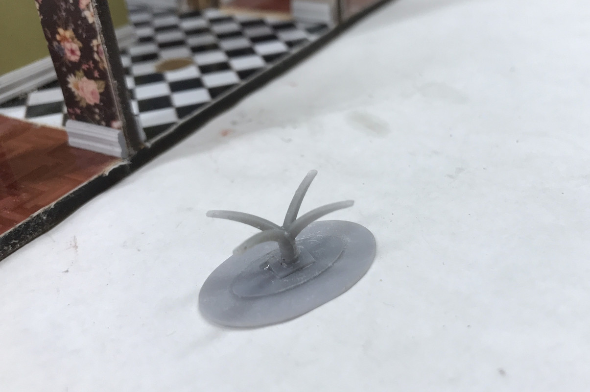
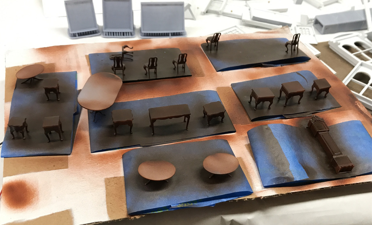
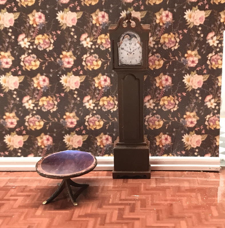
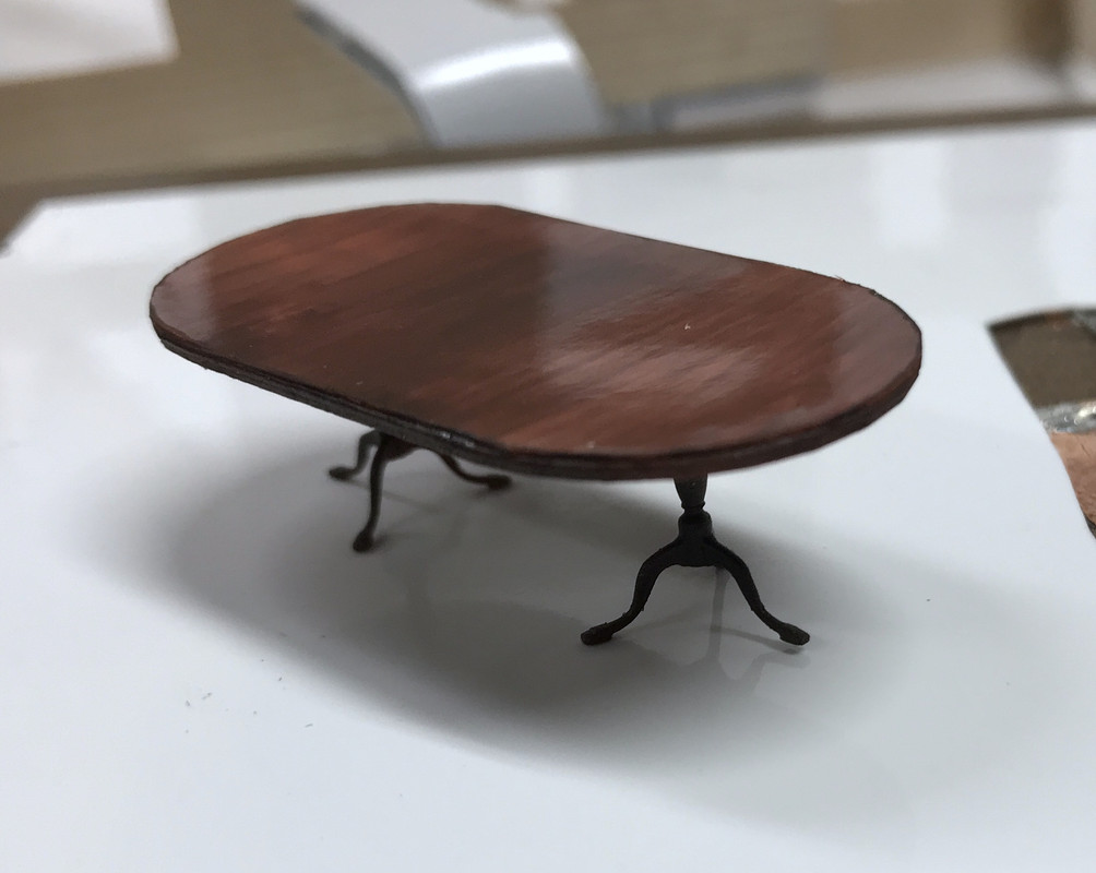
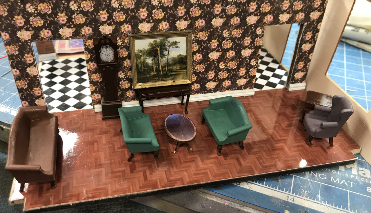
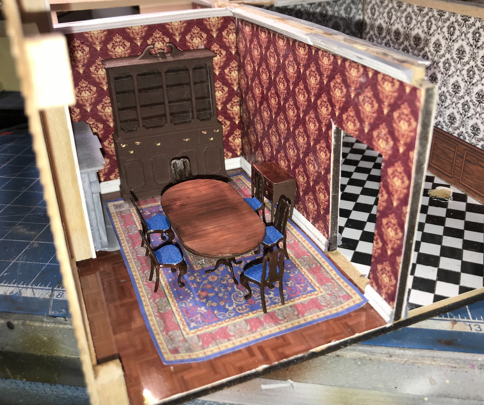
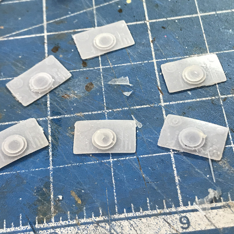
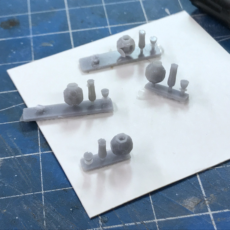
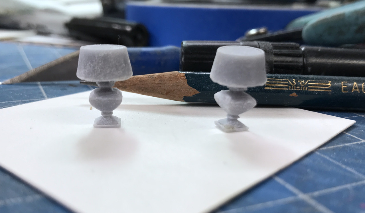
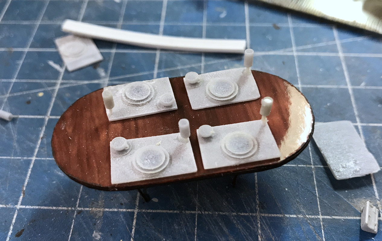
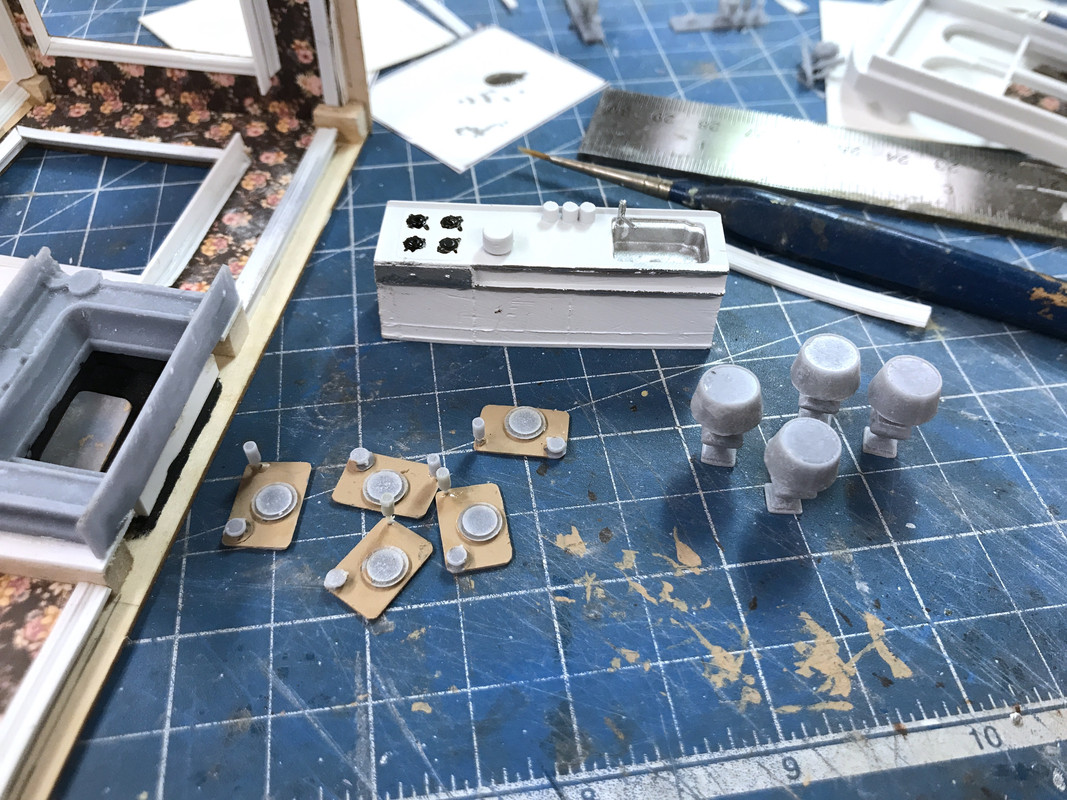
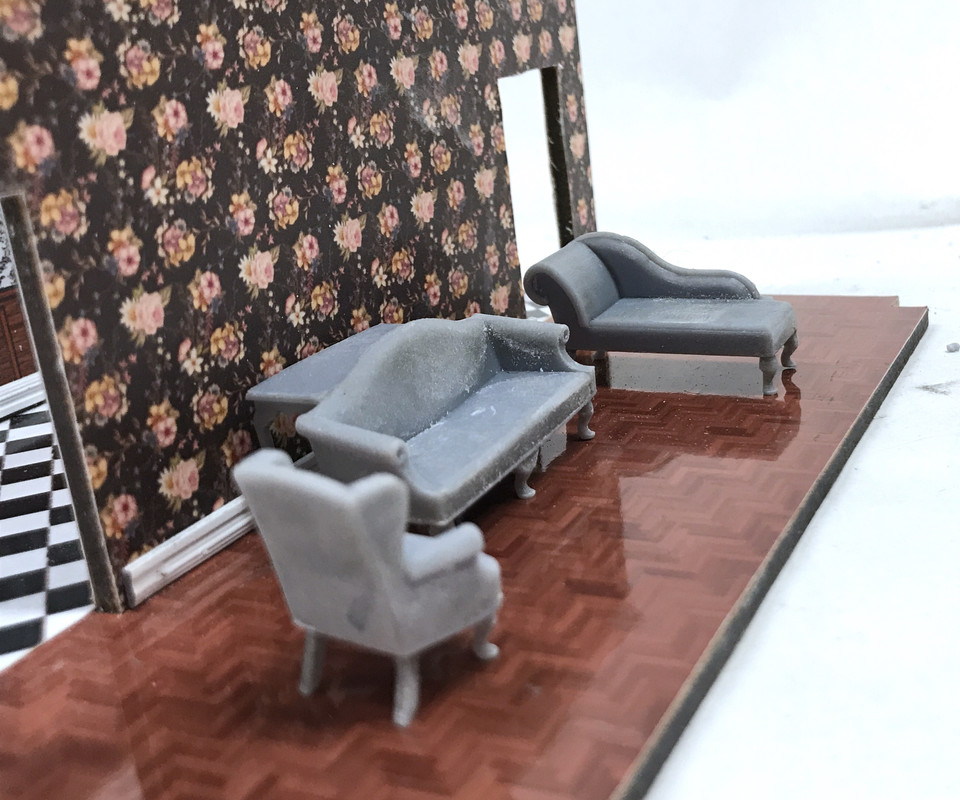
I got the legs installed on all of yesterday’s printed furniture. They look pretty cool.

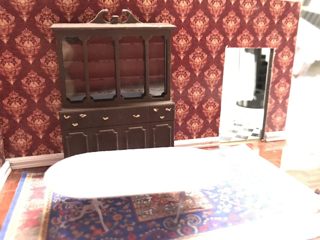
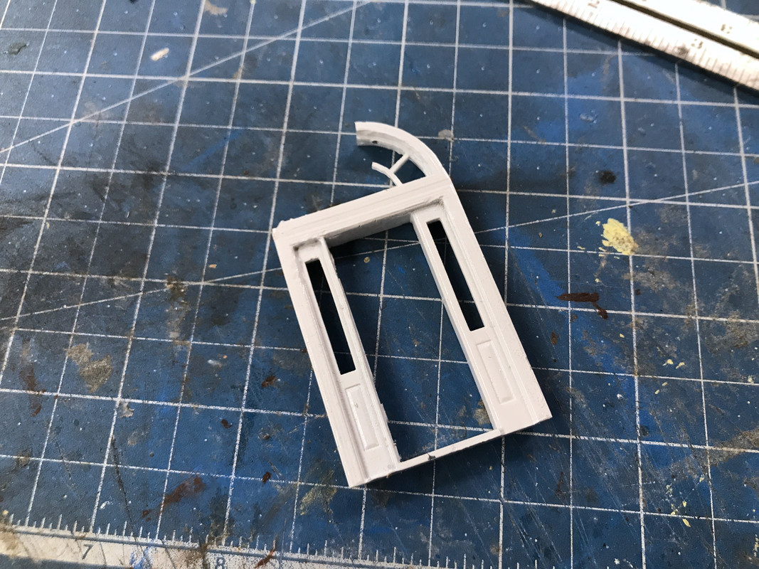
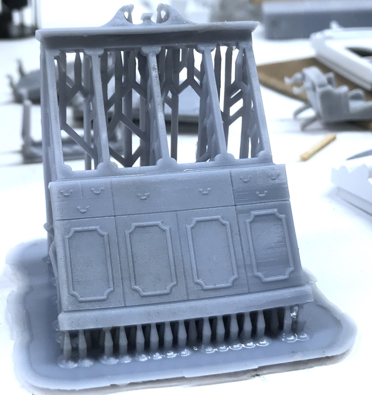
And just before dinner I pulled the re-printed china cabinet front off the Machine and cleaned it. I’ll cut the supports off tomorrow. The drawer pulls did resolve and the surface finish is nice too.

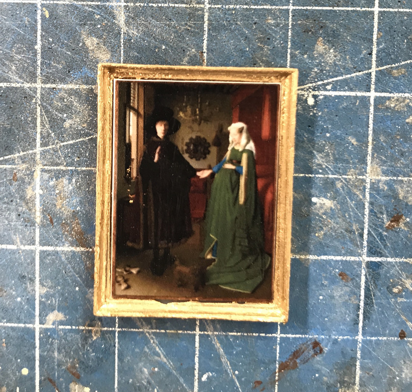
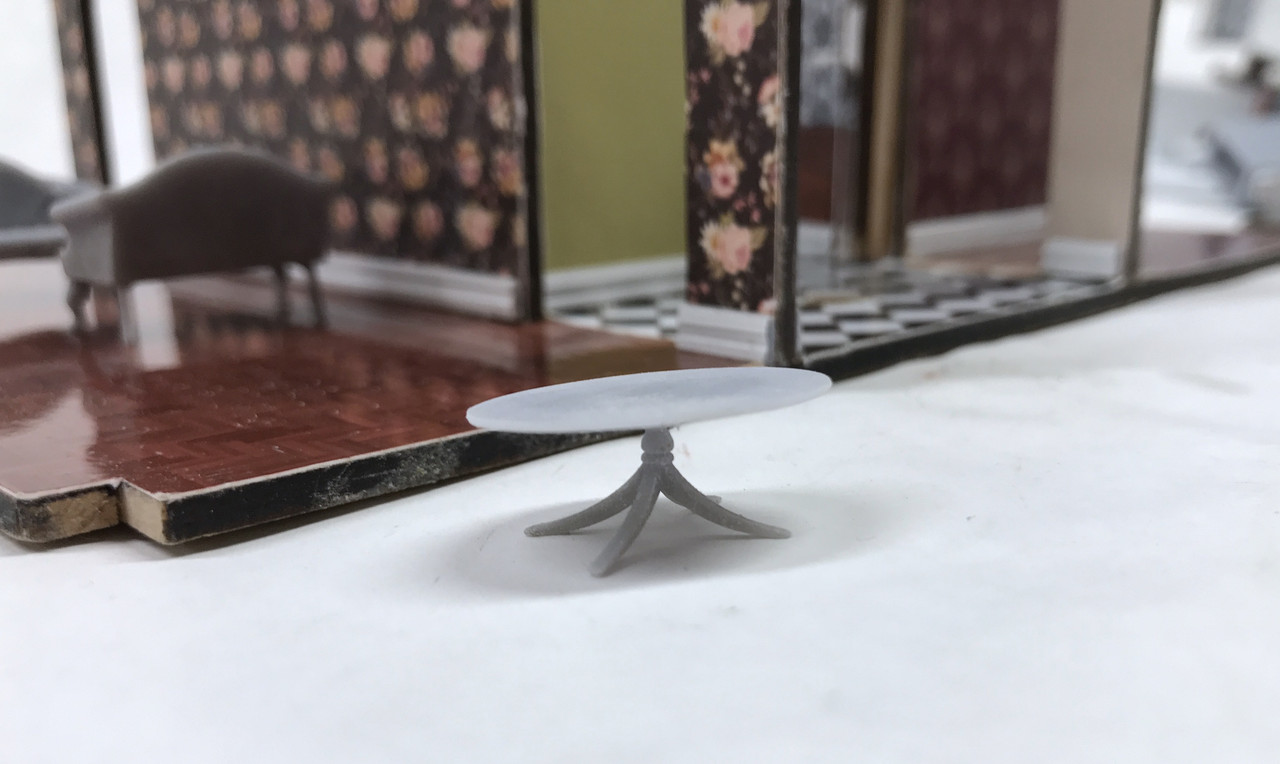
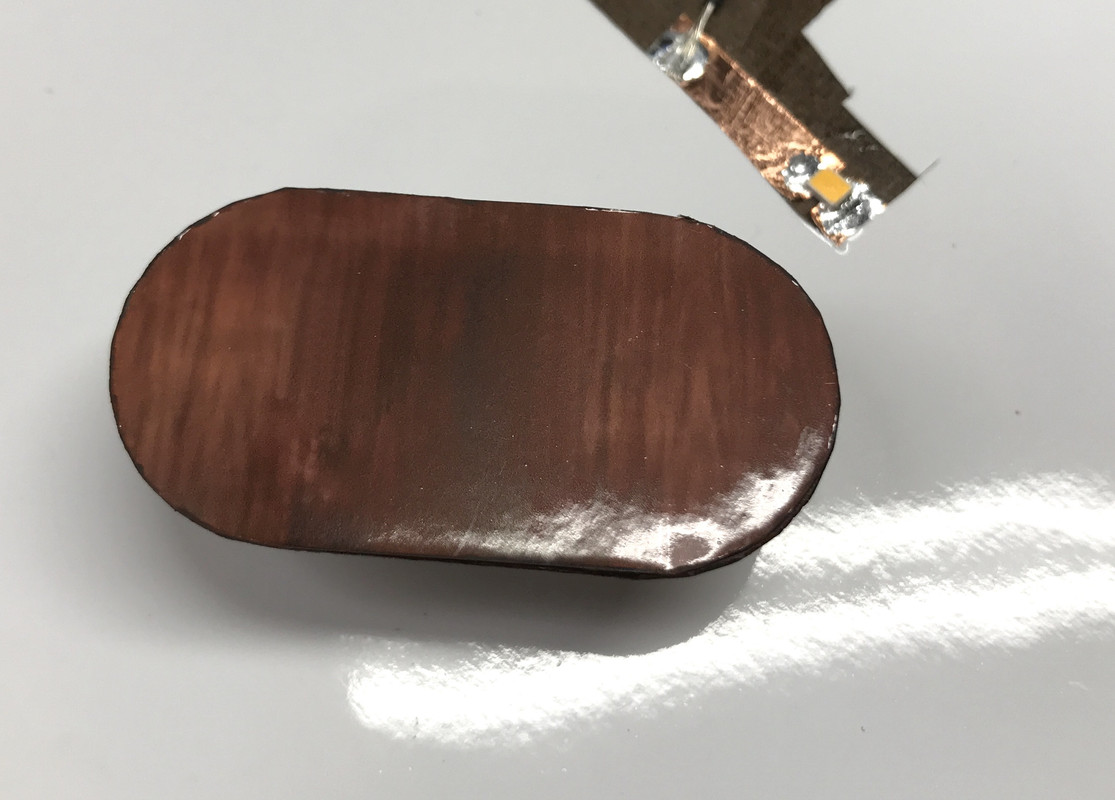
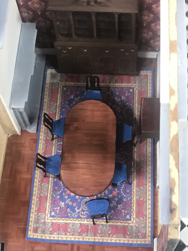
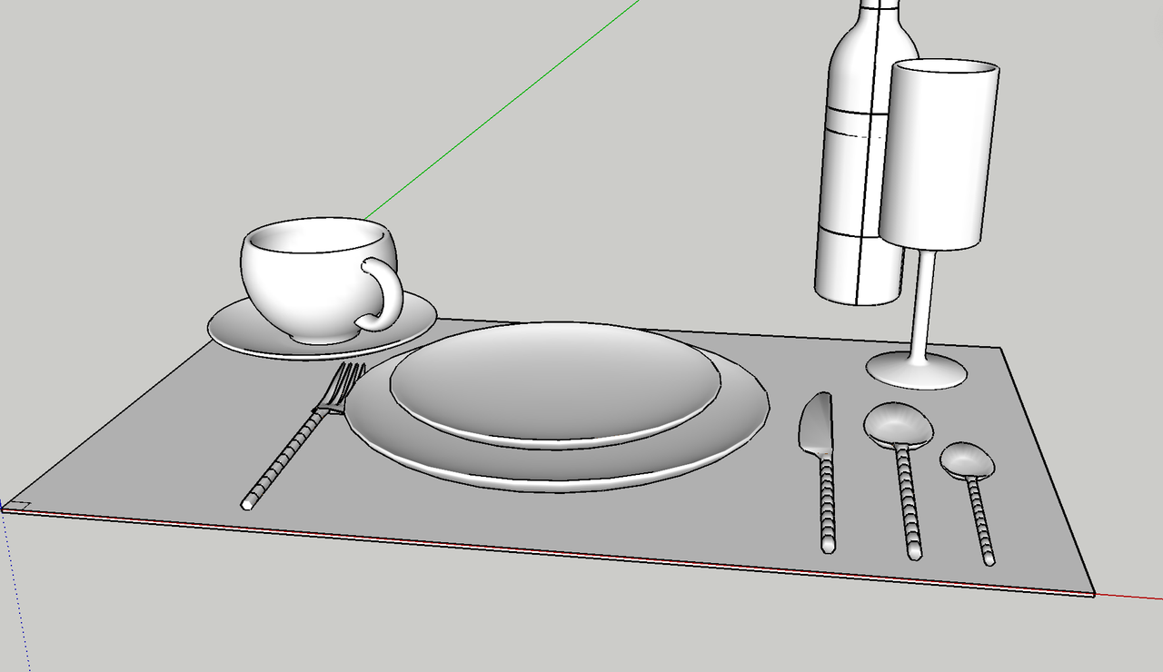
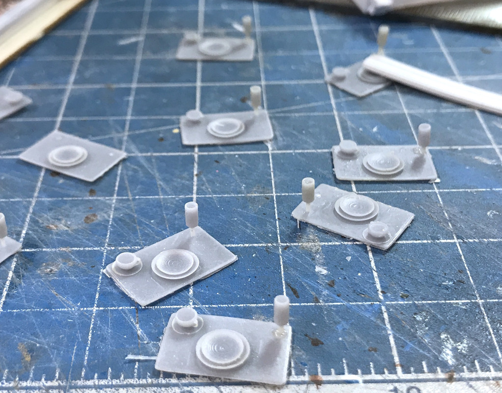
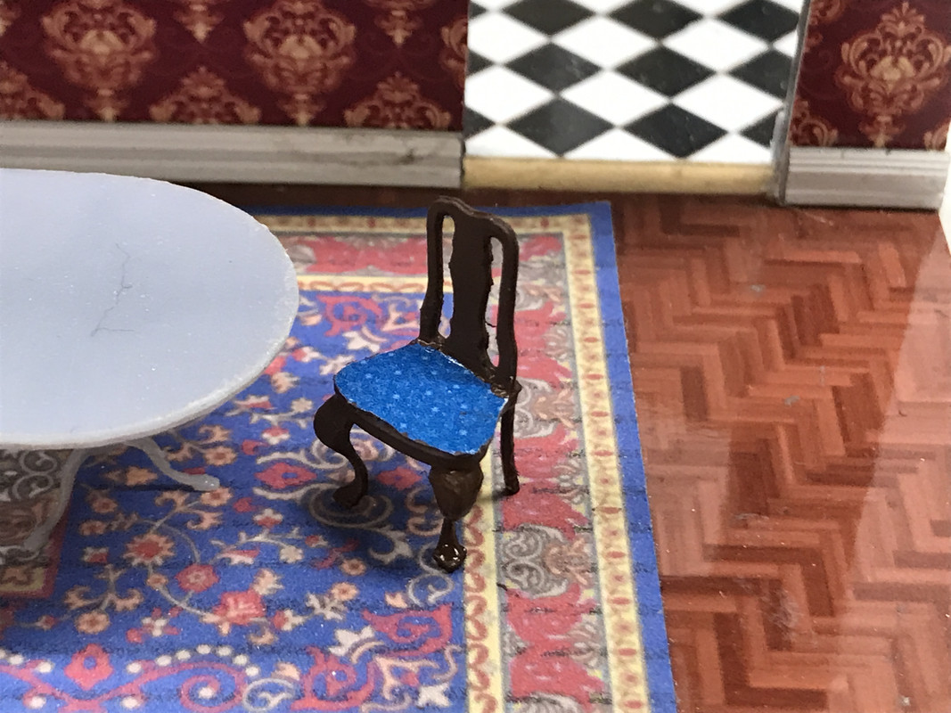
Lastly, I printed the table tops and server in both photo paper and white decal film. I tried the decal for the seat cushion and it worked great.

I then tried the decal on the table top and it wasn’t so hot. I then tried the photo paper version and it will work nicely. Stay tuned. I’ll continue printing furnishing and should have that done by weekend or early next week.

Work continued today on the furnishings with the completion of the china cabinet, the little Baker Server, a gaggle of Queen Anne occassional tables and now two beds are on the Machine being created.

The china cabinet came out about as good as I can handle. I removed the supports before post-curing using the abrasive burr method to prevent any breakage, but I have to say, using the Tenacious/Elegoo ABS-Like resin mix has definitely reduced the breakage. The tiny legs on the server are still somewhat flexible even after post-curing which is a good thing. I haven’t upped the exposure time even though you’re supposed to use the cure time of the longest curing resin in a mix. Tenacious’ recommended time is 15 seconds/layer. I’m running at 9. But it’s working.

This is the china cab front test fit to the back.

My difficulty with finishing this piece was the glazing. I made a rabbet around the inner edge of the shelf portion of the back to accept the clear styrene sheet. I wanted the styrene to set into the groove so the front would fit flush around the perimeter. I did have to sand the front surface of the back which reduced the rabbet’s height so the styrene stood just a bit proud. It was not a problem. The painting, on the other hand, is a problem. I would have loved to airbrush this, but I knocked my Tamiya brown onto the floor on Monday and only have a tad left, not enough to make an airbrush mix. I had to brush paint it. And I could paint it assembled unless I find a way to nicely mask the glazing which has to go in before it’s stuck together. Even with this, it’s not bad.

I bought a Testor’s Gold Paint Pen which really helped in doing the hardware. When the brown is nice and cured tomorrow I’m going to maybe do some gloss on it and then pick out the drawer grooves using some panel line accent. But you have to do that on gloss or the accent bleeds into the flat paint. I also wish I could have put some stuff in the cabinet, but that would be overkill… Ha… ha… me talking about overkill.

I printed two complete Baker servers and I’m glad I did since one set was sub-par, but the other was very usable. I cleaned up and assembled both and tried the decals on the test article. I believe it works.

Here’s the good one ready for the decals.

And here’s the test article.

The tables are in the post-cure box and will need almost no cleanup since they were printed directly on the plate and upside down. The beds do require a bit of cleanup, but I know the scheme is good since I printed the same model for the Tie Hacker’s Cabin.

I also finished up running the wiring down through the turret upper room and drilled the main roof so the wiring would pass down to the porch roof (balcony) and will also tie into the eventual porch lighting. For the porch I think I’m going incandescent so it won’t be too harsh.

The occassional tables printed beautifully. To remove the pre-coat layer, instead of using the hobby knife to slice of the excess, I just sanded the table tops with fine grit until the layer almost disappeared and then I just flick it away with a fingernail.

The beds printed perfectly and I removed the base plate before post-curing, but didn’t remove the supports themselves until after curing. The supports respond to the diamond burr better when they’re hardened a bit. The beds are identical, but they’re on opposites sides of the house and can’t be viewed at the same time. Or viewed at all through the windows.

The tables are very nice and I now have a choice of nightstands: I can use the ones that I printed before for the Hacker’s Cabin or I can use the ones in this set.

I quickly drew some picture frames and downloaded a series of old masters painting to hang on the walls. Using the SU Profile Builder add-in, I picked some different crown molding styles and made them into picture frames. It went quickly. I first imported each picture and placeed it on the 1:1 SU wall to get an idea about how big I wanted to make them. I then drew the frame around each image using the Profile Builder and changing the profile for each. (Is that anal or what???) I shrunk each frame to 1:48 and then measured their width to the nearest 1,000th of an inch. I then went to CorelDraw and set guidelines to exactly that dimension for each frame. Yes! You can work to three decimal places in CorelDraw. I imported each picture one at a time to match the frame that was sized for that picture and placed and expanded each picture to perfectly match the width guidelines I just set up. This had to be done for each image since they were all different sizes and proportions.

This is the famous Jan Van Eyck picture of the pregnant married couple. I put three frames on the plate at a time to print. This was the first batch and the only one that was successful. I had let the crown molding shape taper back as it does in real life, but this left a fragile front edge that didn’t hold up in the printing process. I scrapped the other two and went back to SU and re-drew the frames to square of the back edge so it will be well supported. I print the new ones tomorrow. But this test showed the picture fitting perfectly. As an aside, have you ever noticed that a majority of Dutch Masters painting had the light coming from a window on the left… just ask’n?

I completed the Baker Server. Here’s the actual piece of furniture in our dining room. It’s a lovely piece of Federalist-period furniture. Our dining room is not too large and it’s proportions fit perfectly.

And here’s its little brother (sister). Going photographic was definitely the way to go with this tiny piece. These were decals inkjet printed on white background decal paper. I didn’t attempt to reproduce that filagree at the leg joints. I’m nuts, but I’m not THAT nuts.

I threw the Van Eyck up against a wall (2nd floor) to see if the proportions worked. My wife asked why it was sitting on the floor. And then she answered her own question by kidding, “I know, you haven’t hung it yet.”

It was time to get working on the balcony, specifically because there’s lighting considerations for the porch. Again I’m using the copper foil circuit method and tying this circuit to that of the cupola lighting. The cupola circuit is in parallel to the LED porch lights. Both of these circuits are entering the main house and I’m going to fish the wires down the chimney chase. There is a clear channel the entire length of the chimney chaase. So if anyone is so inclined to stare through the windows and try and find how the wiring is getting below the layout, good luck. You won’t see any wires.

I’m using 1X12s for balcony joists. These needed to be relieved around the window and main door openings.

You can see the two SMLEDs that will illuminate the porch. I’ll probably attenuate them with some paint so they won’t be so glaring.

I’m using a neat laser-cut Joist Jig from Rusty Stumps to lay in the balcony joists. I glued some spacers so the two jigs would keep their orientation. I rarely get the opportunity to use them, but when I do, they’re very helpful. I’m also using that length stop add-on to my Chopper II to cut all the joists. The copper foil has a little thickness so I’m cutting some shallow relief cuts on the joists so the rest of the wood lies flush with the surface.

Notice: when I use separate pieces of copper foil to add or change a circuit, I follow up with solder to ensure that those joints are electrically conductive. Notice also the CL2 driver that feeds the SMLED circuit. The other circuit is that incandescent bulb and will just get 12VDC. Those grain-of-wheat bulbs actually work at a higher voltage so it will burn for a long time.

Just completed on the Machine are two Chippendale love seats that I may put facing each other in the living room instead of the longer single sofa. The living room space is narrow so this may or may not work. I’ll clean these up tomorrow.

Oh WOW!!! I skipped a few days and let you get ahead of me! Love that crazy spiral staircase!!! And everything else looks amazing too!

Well then… let that be a lesson. Don’t miss any days! [:P]

I had strange failures of the picture frames. They kept printing as solid blocks of resin with no bevel framing. I thought it was the printer’s fault. Nope! It’s an aberration in the slicer. Here’s the sequence from the slice animation.

When laid on the build plate the part looks exactly as it should: thick flat backing and the shaped framing.

But as the slice builds, it fills in the entire space between the frames with solid layers, almost to the very top. You can see this looking at how high up the side edge is with the solid filler.

At the very end, the slicer starts building the raised frame, but it’s way too late. I don’t know what’s driving this. The same thing happened to the china cabinet front. What’s even more curious, the slice animation now shows the insides open as it was at the start. It’s like those layers were never there. But they are! And the printer prints them forming a big flat block of resin that ended up in the trash.

I had to reset all the picture frames on an angle and used supports just on the back so they won’t mar the delicate frame designs.

I also had to trash the two love seats I printed. They printed perfectly! But when I dropped them into the living room to see how they’d fit facing one another in the middle of the room, they were HUGE! What??? It turns out that I forgot to scale them. After doing the comparison of sizes in SketchUp, I had to reduce the print size 54% to make them O’scale 1:48. They were probably 1:25 model car scale. They’re now in new files waiting to be printed. Resin’s not cheap and I hate to waste it, especially when it was just carelessness on my part.

I got all the joists fitted for the wide part of the balcony. I realize I need another SMLED over the front door. Three in series don’t seem to be bright enough, but really bright isn’t what I’m looking for here, so I may just insert another one in the circuit and see how it looks.

This shot shows the relief cuts I made in all the joists. Don’t know if it was worth the effort, but this way nothing is pressing on the somewhat delicate copper foil.

I’ve set up to produce some coffee tables, but with the success of the dining table and the Baker server, I’m going to reproduce our Henkel-Harris oval Federalist-style coffee table. I took actual meausurements and pictures and will draw it up.

While I don’t work in the shop on the weekends, I do a lot of stuff. It’s when I do most of my computer design work. I got the Henkel-Harris coffee table drawn and it just came off the machine a few minutes ago. I also designed a grandfather clock based on a nice two-view drawing I found on Google. I also found a nice clock face that will be inserted in the space that I custom-fitted for it. I finished all the joists for the balcony and found that my idea to run the wires down the inside of the fireplace chase won’t work. There’s a chunk of 1/4" styrene blocking the path down to the bottom. Plan B will be to build an external chase to run the leads on the outside of the building. I reprinted the oversized love seats and attempted to do another picture frame. The frame still seems to have a problem. And I dropped the main exterior door and basically destroyed it. No harm no foul. It didn’t fit the laser cut space correctly and really needed to be redone. I re-drew it to properly fit the space and split the door as I did with the interior doors so both sides would have nice clean details especially around the door knobs and dead bolt.

I added the extra SMLED and tested the circuit and with three they were very dim. That wasn’t right! Three of these only drop around 9 VDC and I’m using a 12VDC 30Watt LED power supply. I tested each light individually and lo and behold the middle LED was dim. There was resistance there. I re-heated the solder joints on both sides in case there was a faulty joint. There was! With that fixed all three lights were fully bright.

I’m spending a lot of time looking at all the sub-assemblies to see what’s missing. I found that the rear wall of the lower turret room was showing clapboard. It should not. I cased this is to add thickness to the wall and provide a surface for some molding.

Here’s what the boxed in section looks like from above.

Here’s the broken front door. The new one will be better in many respects. The beauty of having the Machine sitting in the shop is if something breaks you just pull out the file and make it again. Additive manufacturing is definitely a game changer. At least it sure has changed my game. The door’s printing now and it’a six+ hour job, so I’ll be getting it tomorrow.

Now onto the new designs.

The coffee table printed beautifully just like I did with the dining table. The Federalist-style pedestal has for legs that are splayed at an angle.

The print is again two-parts, table top printed flat on the plate face side down. The pedestal is printed also on the plate on it’s rectangular pad. I made three sets in case I break anything or if something doesn’t print well. Of course all three printed perfectly.

The grandfather clock is being printed in four parts: Base, Main Body, Head and Pediment. The base is printing on an angle with supports since it has some reverse curves that wouldn’t print if I did it flat. The body is just sitting on its back flat on the plate. The head is also flat on its back. The pediment is directly on the plate, but drew in some supports for the scroll at the top which I remove after printing.

This is the drawing I found on Google.

This is my drawing as it appears on SketchUp. I beefed up some parts. I added more meat on the base and the finials. The original art’s finials wouldn’t work at 1:48. This image shows one face that I found.

Here’s the face that I settled on. The above face had no hands. This one does. Plus the shiny metal wouldn’t print as nicely. This was the drawing that I produced to make the decals. I also printed the Henkel-Harris table top and the face on photo paper. The actual face is a bit smaller than the image on your screen.

It’s going to be a lovely model. So I still have a few printing days this week to finish up all the furniture. I need to install all the furnishings before putting the building together. With the wiring complication, the floors won’t be easily removable.

still very impressive, that staircase looks great

Thanks!

Mixed bag of work today. The love seats printed and will work now that they’re in the right scale. I printed the Henkel-Harris coffee table and it’s exceptional. The Tenacious/Elegoo ABS-Like blend is producing pretty strong prints. I successfully reprinted the main entry door frame and this time it fits as it should. I also printed another round of picture frames with a different slicer arrangement. Unfortunately, the gremlins are still there and only one came out with the frame fully resolved. The other three had a flat area obscuring the top frame detail. I thnk there’s a bug in the slicer and I’m going to find out why. Lastly, I started creating the interior wall detail for the main outer building walls. It’s time consuming, tedious, and frankly, I’m not sure it’s worth it. It will only be viewed obliquely from the outer windows. In fact, I’m not sure you’ll see any of the interior walls that are not actually facing the windows. The jury’s still out.

First the love seats. Here’s a top view showing how they’ll sit in the living room.

This is the coffee table.

Here’s how the bottom looks. I held the pedestal to the table top with Bondic. The UV curing light shines through the resin to harden it underneath. This only works for the UV resin since it’s partially transparent to UV 405nm.

And just for fun, here’s what 1:48 looks like on 1:1. I will apply an image of that inlaid tabletop to the model so it will look just like its big brother.

The front door fit so tightly that I needed to relieve the door opening and shave some off the resin part. But it’s the way I like it.

And this shows how it’s fitting the opening. After these images, I glued the two halves of the door together, sanded it for fit into the door opening and then glued it in the open position with Bondic.

While working on fitting the door I realized that I needed to address the main wall insides. I started with one window and saw what I could do. The resin windows frames protrude into the room by about 0.080". I wanted to pack this out so the wall would be flush with the window. It turns out that a sandwich of one piece of 0.017" thin ply and two layers of Bristol Board made the wall flush with the window protrusion.

I glued the new wall in place and started adding the trim molding using the undersized baseboard left over from before. I then fabbed a window sill out of some 0.030 X .156" styrene strip, and finished it off with some more trim on the bottom. Looks spiffy, but was a ton of work and you won’t be able to view it unless the front wall is removable.

Viewed with the wall in place and it looks okay.

I then added baseboard and wall paper to finish it off.

I made a mistake with this wall. I had the wall upside down when I scribed the partition wall position. I was off by about a 1/4" which I can add. But this begs the question. “Does this effort amount to anything of value?” It took a long time and a lot of fussing to do this little bit and there will be about another 8 windows where this needs to be done. The work I’m doing with the furnishings and the inside wall decor is substantial, but you will be able to see some of it through the generous windows, but the walls behind the windows are really going to be hard to visualize, if not impossible. I need feedback.

Another multi-tasking work day… 3D printing, airbrushing, window building, interior detailing, and conferring with my darling wife when stuff kept coming up on the 24/7 news shows.

I built the 4-part grandfather clock and wasn’t satisfied with the results. Too many details were lost in the cleanup and some added edges due to the residual from the pre-coat layer that forms part of prints that are directly on the plate. I then quickly redesigned the clock. I needed to make two changes to ensure that the parts printed with fidelity. The pediment had to have some supports added in the drawing. The slicer won’t allow you to put specific supports in one place with the same accuracy. I also needed to change how the base profile was built so it had plenty of support and still showed the details.

Here are the added supports to help the finials print. As you’ll see, the only finial that was at all successful was the center one. While the others printed they were simply too delicate to hold up. I printed the clocks six-up on the plate. I really needed all six to get a good one. In actuality these supports are really tiny and were easy to remove with a #11 blade. I attempted to use the Dremel with the diamond burrs, but the vibration alone was enough to break them off. This was the orientaton on the plate so these details would suddenly appear in parallel to the build surface and this often is not very successful. Furthermore, you can see that the bowl of the finial would start printing attached to nothing… i.e., an island. Islands don’t work in a resin printer and simply float away when the plate rises to begin the next layer. The diagonal supports would grow and catch the newly forming islands. It worked.

The base change involved making the front profile full-depth and then making the side details shallow with a solid backing. This enabled both to form while laying flat.

The result was very pleasing seeing all six clocks reasonably well formed. If you look closer, however, you’ll see that even on the plate, some of the tiny finials didn’t form or were destroyed just by brushing on the alcohol cleaning wash.

After separating them, ultrasonic cleaning and post-curing here are the passel of clocks. You can see that only a few have all three finials.

I tried to salvage side finials and Bondic them on to make one good one, but I couldn’t even remove one without it being destroyed. So I made one really nice clock without the side finials and it looks great. If the model was 30% bigger the finials would have enough mass to maybe hold together. They’re so small I couldn’t even machine real ones out of brass. You’d need a true watchmaker’s or swiss-type lathe to machine little pieces of jewelry like this.

Vallejo Acrylic Paints had a color in their Air series called “Mahogany” and it was the perfect color for all of this period furniture I’m creating. Vallejo flashes off pretty quickly, but it needs at least 24 hours to fully cure. Otherwise, it’s kind of sticky and you really shouldn’t handle it. You can see the clock in the lower right. The big table tops are not fully painted since they’re receiving actual top photo images.

I printed another pile of smaller cross-section base boards if I’m continuing with covering those window walls. I did a photo test to get an idea of how much you could actually see through the windows. And yes! You can actually see those attached walls so I’m going to continue with the wall covering process. The windows are pretty big and do let you view the interior.

While I was trying the exterior wall for the above picture, I discovered this.

When I did the “field mod” by adding that back wall to the dining room (to better display some furniture), I neglected to see that the wall was smack dab in the middle of a window. DOH! That wouldn’t happen in a real house since you’d be in the room looking at that window. I will have to change this. The 2nd floor’s partitions sit just to the rear of the fireplace and just touch the window opening. I knew what I was doing there. I didn’t in this case. Field mods always get me in trouble.

I stopped work on this part because, in addition to painting the furniture, I airbrushed the new front door assembly AND the laser-cut Cupola windows. With my ADD attention now looking at the cupola windows I decided to see how they fit and they weren’t great. I believe the cause is due to the inherent resolution inaccuracy with FDM machines. They have inbuilt difficulty in forming tight right-angle corners. If the cupola was resin printed I believe the tolerance would have been ridiculously close. As it is, there is a 1/32" gap on the window tops.

I had drawn window stops into the cupola design, but they only FDM printed on one side of the opening AND they didn’t really have a lot of definition. I added my own stops. I used 0.060" sq. styrene held with med CA.

I had to trim the laser-cut window just a tad in height (about 1/64" or less) so they wouldn’t be deformed. I then built one full set. I was surprised that the acetate glazing is a little undersized in width. I designed these pieces so it’s my problem. It’s never the laser cutter. It’s always me.

I really needed to get these windows figured out since I can’t finish painting the cupola until I knew how the window would interact the space. I’m still in a quandry about how to deal with the strand lines on the cupola. It may not be a problem based on the viewing distance. I’m spoiled. The resin printer produces such amazing surface smoothness especially when parallel to the liquid surface. I may put some flexible trim to encase the window and close all those gaps. The strand lines are especially noticeable in the arches.

Whew! That was a busy day. Tomorrow I have my semi-annual Dr. checkup. In this case it’s an annual since it was Covid-delayed. I’m 75, have the usual controlled, pre-existing conditions that almost everyone of my age has; high blood pressure and elevated cholesterol, both of which have been well controlled for 30 years. Thank you modern medicine. I also have Afib which is surprisingly easy to live with. That too is managed. So all in all, life is good. On Friday, I’m escorting my daughter to pick up their new Tesla Y in Cincinnati. They will become a 2-Tesla family. Needless to say, they’re really happy with electric cars.

Spent some time further refining the drawing I made upon which this project is based. As I’ve messed with interior details, partitiion placement, etc., some stuf got out of kilter and I needed to put it back. Mainly the problems were concerned with the turret walls and windows. I also added a TV antenna.

SketchUp has many different drawing styles that you can use. This one simulates a watercolor. It’s fitting since this house was based on a piece of artwork. I also finished coloring the porch, balcony surface and getting all the trim changed from Kelly Green to blue. I’m using blue on the model. I had green trim on the Nighthawks Cafe and this would be right next door.

There’s still a large amount of work to do. The table with all the parts is overwhelming.

Astonishing work!

Your insights on Sketchup have illuminated my own poor (self-tought) efforts with printing.

And your chandelier has also given me insight as to how to complete my own first LED lighting project.

I look forward to seeing more.

So you’re not making working grandfather clocks? [;)]

All joking aside everything looks fantastic! Shame about the lost detail on the clocks but they still look great!

Thanks guys! I really like inspiring others. It keeps me going.

The lost detail is a non-issue. As you can see, the clock is a reasonable facsimile and will serve well. I’d have to shrink myself down to 1:48 to make a working clock. Ugh! I’m sure there’s some demented craftsman somewhere in the world who would attempt it.

Sitting along side is the Henkel-Harris oval coffee table that graces our living room. The photo was a slightly different contour than the actual top, and the photo paper is relatively thick in this scale. When I painted the white edges so of the paint wicked into the photo paper. I’m being really anal here. You’ll barely see it through the windows.

I still have to put the table top image on the dining table and the decals on all the dining chairs. I had them staged today to do, but didn’t get to it.

Working with Ed Tackett at U of L’s Additive Manufacturing Institute we came up with a successful solution to printing the picture frames. He was having the same slicer abberations that I was getting so he tried printing them without the back material and this produced a successful print. Based on this finding, I re-drew them without any backing, just the frame perimeter. This worked. I got four successful frames out of 6 which gives me five wall hangings since I already had one from the previous attempts.

Instead of gluing on a flat piece of styrene for the back, I’m just going to use the photo paper perimeter to the glue the image to the frame. Here’s a frame placed on a John Singer Sergeant masterpiece. Actually, not trying to cut the picture to fit inside the frame results in a much flatter image. If the cut picture is just slightly oversized the edges would curl up and distort the reflectivity of the image. Silver lining…

I’m using the Testor’s Gold Paint Pen for these frames. I find that the felt tip is too broad and crude for detail painting so I placed some drops on a piece of Press-n’seal and thinning it with a few drops of low-odor mineral spirits so it brush painted smoothly. It’s a great metallic paint with lots of luster.

I decided this morning when waking that I needed to add some lighting to the attic. I had originally thought not to do that, but there’s that nice stair rail surrounding the stair well in the attic that would be a shame to not be seen. I used copper foil with two SMLEDs and a driver. Again, I used the plain white photo paper as a ceiling cover.

Not as much production as I would have wanted today (Friday… no work on the weekend), but I took time out of the day to re-drew all those picture frames. I had to clean the printer twice due to the failed frames. Nothing was on the vat bottom so it was effort without a reason. I’m using the EPAX non-FEP film which is very forgiving. I also had painted the balcony balustrade upside down. I mistook the bottom for the top and vice versa. The wide part is the top rail. It was a beautiful day so I stuck them all on a piece of cardboard and painted the top rail with the Rust-oleum white one-coat rattle can.

I’m reaching the point where I need to delineate a check list to keep track of all the details needed to be done for completion. The table with all the parts is such a mess that it’s really easy to get lost in the weeds. Besides, thinking about the sequence to finish is helpful in deciding what to do and how to do it.

Happy Monday. For about 1/2 my readers I can assume that it’s VERY HAPPY Monday. For the other 1/2 I hope they can find peace. There was no fraud. It was one of the cleanest electrions we’ve had AND it was done in the midst of a raging epidemic with all kinds of obstacles and yet, the highest vote percentage since 1900 before women got the vote. Go America!

Spent most of the day painting furniture, making wall art and fixing that misplaced wall. First thing I did was apply the photo to the dining table top and trimming the edges. I learned in doing the coffee table to be more careful with the trim painting and it worked. I glued it on with dots of med CA instead of the pressure sensitive stuff. It was easier to control in this situation.

The top is very (intentionally) glossy. There’s a couple of schools of thought about fine furniture finishes. Henkel-Harris and Kittinger used a hand rubbed satin finish. Kindel and Baker used high gloss. I went with the latter. Applying the photo worked exactly as I thought it would.

I applied some Tamiya gloss to the occassional table tops and called them done. I then mixed up some custom colors and painted the upholstered seating. I was able to attach the artwork to the frames directly using some strategic med CA.

What’s missing are knick-knacks and other items on the tables. I may 3D print some stuff. I also need some table lamps, but I’m not planning on lighting them. It’s possible, but not easy in this scale.

I got the decals applied to the dining room chairs. So that room is complete. Again, nothing on the bare table and server. In this picture you can see the moved back wall. Took a bit of surgery to do that. I had to recover the back room floor since there was a big slice out of it where the wall previously was attached to the sub-floor. I’m going to make that small space into a kitchen. I’ll print some stuff for it. I already have appliances that used to populate Loopie Louie’s Appliance Emporium. Once you have the files, it’s very easy to make more of something.

When you think about it, the fireplace location is ridiculous. It probably should have been in the midwall and possible two-sided. Oh well…

Here’s a view through the kitchen window showing how the new placement just slides by the fireplace and hits the rough opening. There won’t be room for any molding on that wall.

I did put together a rough project plan today. working steadily, the project will complete sometime in early January. That’s assuming that we make no family trips and until the vaccines are readily available, travel is still a no-no. There’s a ton of work to do and I’m glad I memorialized it because it’s real easy to find yourself painted into a corner (literally and figuratively).

Lots still to do…But, at least now I have a road map. One of the programs I really miss with my MAC was MS Visio. I suppose I can run it on my Windows emulation. It had a very easy Gantt Chart facility that I used all the time. It was also terrific for flow charting. I became expert at flow-chart with business groups in real time. We’d project the program and I would build it with the group. No flipcharts and no transcription. Visio was a drawing program for idiots. I’m going to look into it. I tried to get a Gantt program for OS, but wasn’t happy since most wanted monthly rentals. I don’t do enough of this to justify the monthly rental of darn near anything.

Exercise day and some drawing time. I decided that there should be a small kitchen in that back room. It didn’t take me long to find a small Japanese style kitchen on the Podium Browser. The Browser is a part of the package you get when you purchase the Podium rendering package. It has tons of 3D drawings that are fully textured that you can drop into a drawing. I then added one of the refrigerators I created for the Appliance Store. Didn’t take long to prepare it all for 3D printing. It’s on the Machine now and will be done at 9:00 if it all works okay.

Here’s the kitchen and how it fits on the wall.

And here’s kind of what it will look like through the windows.

I decided to brush paint the cupola exterior trim. I first tried some Tamiya Gloss White, but its coverage was very poor. I thought about spraying gray or white primer, but then I thought to decant the Rust-oleum White Primer/Top Coat. I was able to brush it on and in 3 coats covered pretty well. The paint is high solids so it partially filled the strand lines on the FDM-printed part. I may put one more coat on tomorrow to finish it off. I also put a single coat on the shingle area to give more for the self-adhesive shingles to hold onto.

I also finished assembling all the cupola windows and making sure they all fit before painting.

I finished up the one exterior wall I started last week and started working on the living room front wall. Once I decided to do these, I got right to it. It’s also the first item on the completion check list. The cupola was not, but since I already started that last week I decided to get it off the bench as a finished sub-assembly. These interior walls will go faster now that I have a scheme that works.

See y’all tomorrow.

YOU MAKE ME SICK ! ! !

Sick with Jealousy! ! Why? Well, you are all the way over in Kentucky and not here in New Braunfels,Tx. and a member of the RailRoad Museum I am President of. Boy, could I use a machine like that. I would be turning out Turn of the Century yachts constantly! Oh, and 1/16 scale Rail Cars of Note. ( The Old Time Moguls Cars)

I do my yachts from Kitbashing and stealing parts from other boat models bought with damaged or missing parts. Your Skills are KILLAH ! That house seems to be one that everyone even LEGO like to do. I can’t stop following this. Build on my friend ,You caught my interest! The More I think about it, I could turn out 1/48 scale Dining and Club cars for display or sale.

I keep seeing that Cupola roof with Copper Sheathing between the windows, with a nice patina of course! Please don’t forget the weathervane, Okay?

It’s your kind of feedback that keeps me writing all this stuff! Thank you! I went on Google Earth to find New Braunfels. It’s basically a suburb of San Antonio. Must be a nice place to live.

I would have liked to have had this capablility when I was doing ship building too. There are some great 3D printed details available from Shapeways, but it will cost you. If you’re going to do it yourself, you MUST master the drawing process. 3D printing in 90% 3D drawing and 10% running the machine. Get the drawings right and the printing becomes an afterthought.

The little kitchen printed nicely and it’s ready for paint and installation. I was happy that the slender faucet printed well. I watched it grow on the slicer and it looked like it was going to work. I had to add a slice of styrene on the front of the range hood. I thought this surface was suspect and I was right, but it didn’t jeopardize the job.

I put another coat of white on the cupola window frames, this time using the Tamiya Gloss White. It’s pretty good and I don’t think it needs another coat.

I designed and printed some bricabrac (spelling?) including plates on placemats, vases and some table lamps. This was a marginal success. Some stuff is just too unsubstantial to print. Here’s the drawing used for the place settings.

The cup and wine glass didn’t work at all and left little tiny bump on the Vat Film. With the EPAX film I’m using, you can pop off this debris and just go back to printing again. It’s very forgiving. The flatware shows up but it’s so insignificant as to be not really there. With very careful work with the Molotow Chrome Pen I may be able to make the flatware visible. But the plates did work.

I found some various vases and a table lamp on the SU 3D Warehouse and attempted to fix the drawings and then print. The thin walls of the vases had to be filled up. I should have done that with the coffee cup and wine glass, but didn’t. Those walls in 1:48 would have been in the few thousandths of inches in thickness and I don’t care how good the printer is, it ain’t going to resolve that because the resin simply doesn’t have the wall strenght to pull off the FEP.

I put those diagonal supports from the lamp base to the shade so the shade would start printing. I also doubled the thickness of the lamp stem. Even with that 2 or the 4 lampshades broke off when cleaning them up. That crazy faceted vase had another problem; a lot of the interior was hollow so some failed, again, due to the thin walls.

You can see how one of the side walls of that vase broke loose. But I do have some successes.

And I got two lamps complete and the other two will be fixed with a piece of brass rod holding the shade. I had to make the shade solid. I suppose a piece of paper in a cicular tube could be used to make a “real” shade, but you’re not going to be able to look down on these. You’ll only see them from their side, so the solid shades will work.

I spent more time decorating the exterior walls. I got the right side done and started the left side of the fireplace. I ran out of wide baseboard and crown molding so I printed some more late this afternoon. I’m definitely suffering from AMS on this project (Advanced Modelers Syndrome). I mean, seriously, mitering crown molding on a 1:48 model railroad structure. This is similar to the work that Lex Parker does on his narrow guage layout. He’s Canadian so maybe that’s why.

Here’s another view of that crown corner. This is when I ran out of stock. Again… run out? Print some more. Just save the files. I’ve kept these trim files on the thumb drives since I suspected that I might have to re-run them. By printing on the plate, the moldings take all of 25 minutes to do a run.

I have to paint the fireplace fronts. Still thinking of what I want to do with that. By packing out around the windows gives a real nice scale thickness to the building’s walls.

I had four to five days to finish these interior walls and I’m sticking with that estimate. It’s painstackingly slow work.

Oho!

That Engine would look so good with another one in the engine room of a 1/48 or 1/87 scale ship model engine room! I must make a correction in your thinking though. San Antonio is a suburb of ours! At least when I go to Hill Country Hobbies it feels that way! LOL.LOL. Geez this has got my brain in high gear. I even went so far as to put P.E. Rails on a paper ship because of this. You Know, How can I make this better?

One more thing. Are you going to put the Ghost of the Captain and Mrs.Muir in there? That looks so period correct. I am amazed at how you’ve covered all those bases. Juest a thought.You can get labled Wine Bottles and such from LEGO to use as patterns.This includes Flutes and Flatware. Well, they did offer it for a while.

You comment about “All how you look at it”, reminds me of the Stan Freberg, “Columbus Discovers America” bit on his classic 1960s album, “Stan Freberg Presents: The United States of America - The Early Years.” For the uninitiated, Stan Freberg was an outstanding comedian and satirist in the 1950s and 60s. He was often on Ed Sullivan’s show. (I’m really showing my age here.) The album featured a series of vignettes accompanied by great music. In Columbus, Freberg tells the natives who he met when arriving, “I want to take some of you back with me to prove I discovered you.” The chief responds, “You discovered us? We discovered you on beach here. It’s all how you look at it.” It was classic. My buddies and I at Michigan State in the 60s, played the album so much that we had the entire thing memorized and used a lot of one-liners in our daily communications, just as folks do quoting famous lines from Princess Bride. (I do that too). I then got my kids into the album and my daughter even plays it for our grandsons.

Freberg passed in 2015 at 88 years old. He was one of my all time favorites. If you’ve never heard about him, check him out on Wikipedia. So, all how you look at it has some comic significance for me. Sorry for the diversion.

Had 2.5 hrs in the shop today, but don’t have too much to show for it. I spent a lot of time preparing the new crown and baseboard moldings for paint, painting the kitchen and getting a reasonably successful print of the dining room stuff.

To make it a bit better I went back to the drawing board and redesigned the wine glass, coffee cut and flatware. I also scaled it a tad bigger. The scale factor for 1:48 is 0.021. I used 0.024. As it was, even with my changes, the flatware failed to really materialize, the wine glass had a 70% failure rate which I corrected a bit by gluing them back on with Bondic. The coffee cups were more successful with some actually forming the finger loop. I made the insides of the cup and glass solids. I also attempted to raise the silverware off the surface and put support structure underneath, but it was just too small to form separate resin layers. I printed at 30 microns. You can just catch the shadow of the silverware. I think I’m finding the downward limit of detals that can be successfully reproduced by a LCD resin printer. The printer will print it, but you can’t do anything with it since just dropping it in the ultrasonic cleaner breaks off the details.

Here’s the placemats on the table.

By upsacleing, the placemats took up more table space so I sanded the placemat down a bit, and of course, knocked off a couple more wine glasses in the process. The above image shows these sanded placemats.

I painted the placemats in prep for painting the rest. I also painted (poorly) the kitchen unit. It was the end of the day and I was rushing. When I’m rushing I usually make a mess of things. You’ll also notince four table lamps. I did put a piece of 0.032" brass rod to re-attch the shade to the base. That will give me lamps for each of the four night tables in the bedrooms.

I got more work done on the next room and with the newly printed molding got back to adding crown and baseboard.

I also finished painting the beds. So there’s that. Tomorrow won’t be full session day either. I’m now tasked with picking up grandson #2 at high school on Fridays. I’m making a stop at the hobby shop to drop off more decals I made for the plastics department manager.

Oho!

Question! Are you going to put a stuffed Sailfish or Marlin above the fireplace instead a Moose or Deer? Please don’t . Add a Painting from one of the more interesting artists.