Edward Hopper: House by the Railroad in 1:48 (start to finish)

I mentioned this “super-project” for my O’scale Railroad in my Ryefield Model Sherman build thread in Armor, and it was suggested that maybe it would be something to post in this forum.

In addition to military models (mostly in 1/32 and 1/35 scales), I’ve also been building an elaborate 39 X 15 foot O’guage model railroad.

On this railroad are a number of custom buildings that I’ve desgined, drawn and built in 1:48 scale. Lately, I’ve settled on doing Victorian architectural subjects and have delved into more sophisticated designs. One of my buildings was an old plan in a 1957 Model Railroader given to me by an uncle in that era. It was a corner bar with a Mansard Roof including a turret. I kept this drawing in a file for years, and then a few years ago decided to build it. This time I wanted to include a rendition of Edward Hopper’s masterpiece, “Nighthawks”. I had to learn a few tricks including, but not limited to, turning the turret roofs on a metal lathe, and having 1:48 bar stools laser cut. I also had to bend some plexiglass to make the curved front glass window.

My next Victorian attempt was the re-creation of an extant building in the Bronx, NYC, called the “Bronx Documentary Center”. It was picture that appeared in the New York Times Travel Section which I redrew in SketchUp. The original building was four stories high, but its height and length were too much for my little village. I took out a floor and shortened the depth and then had it laser cut. It was the first time I had any parts done by 3D printing. It was a very successful project.

There was one other building that I wanted to try. This one is Edward Hopper’s “House by the Railroad”. The subject of this American impressionist painting is purported to be a Victorian mansion in Haverstraw, NY. This painting was also supposed to be the impetus for the “Psycho Mansion” that’s still at Universal Studios in California. Drawing this building was a challenge for me and I had to learn many new techniques in SketchUp. Of particular difficulty were the elaborate Mansard roof windows and the cupola.

I had take artisitc license in my design. Much of detail in the shadows was completely obscure, and I had no idea what was happening on the right side (or rear for that matter). I decided to put the turret in the center as it is in the Haverstraw house. I’ve seen houses like this with the turrets centered or assymmetrical.

Over the last few months I printed all the architectural details including a elaborate three-story staircase and fireplaces. The one-piece cupola was too big for my little Elegoo Mars resin printer. I had this printed at the University of Louisville’s comprehensive 3D printing lab. I had the flat parts laser cut by Rail Scale Models and have started construction.

The story behind this build is comprehensive and it will take some time to complete. Furthermore, this forum is not an easy one in which to contribute because of having to export all the images to a picture service and then import into the text. So I don’t want to spend the time to do a complete build thread unless there is interest.

So please let me know if you’re willing to spend a few months of your time following along. If there’s a positive response, I will regale you with the entire process, all the way back to creating the parts.

Very interested!

To paparaphras the famous line:

“If you post it…they will come.”

Methinks ;

You should do this. I and others would benefit. G.J.Geracci

President–New Braunfels, Tx. Railroad Museum

LEGO has one that I " Restored" into a liveable home with a rear deck and a pool! We use LEGO for some of the sets in the “0” and 027 Layouts. We use more in the " G " Scale because they are outside.

I just wrote about five paragraphs of brilliant thoughts and then, inadvertantly, opened another web page on top of it without hitting the + sign and lost all of it. DOH! It is not the first time I’ve done this bone-headed maneuver and won’t be the last.

Three people saying “GO” is sufficient for me to continue. This site is a bit annoying for two reasons, 1) it does not use the OS spell checker which I need, and 2) has an archaic image adding system where all the images must be uploaded to an image site and then downloaded here. I post on many sites and this one is the most awkward. Be that as it may, it’s an important site with many participants so it is worth the effort.

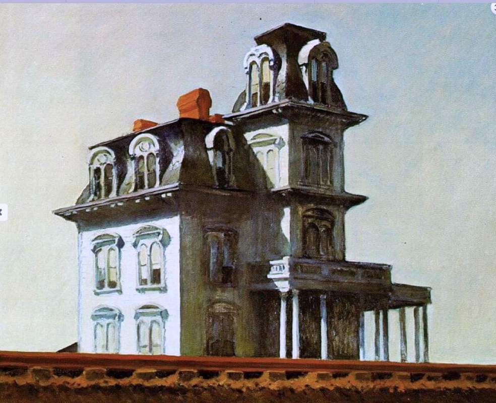
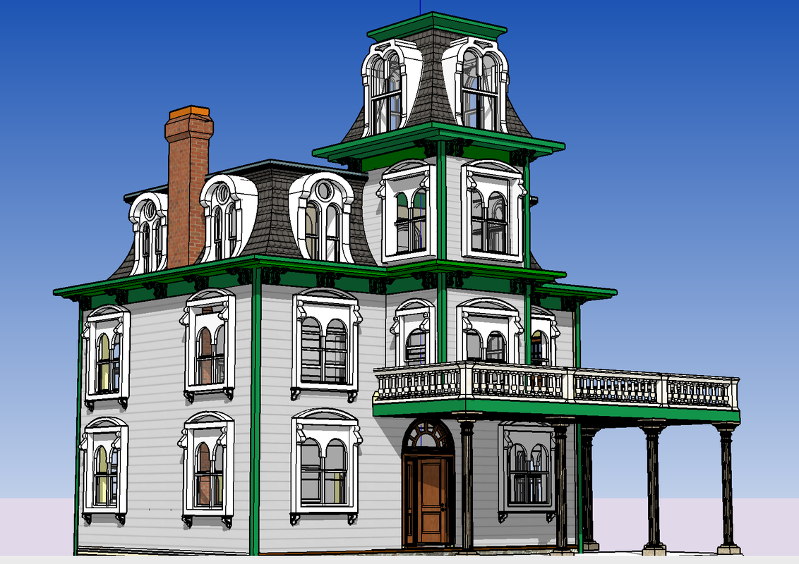
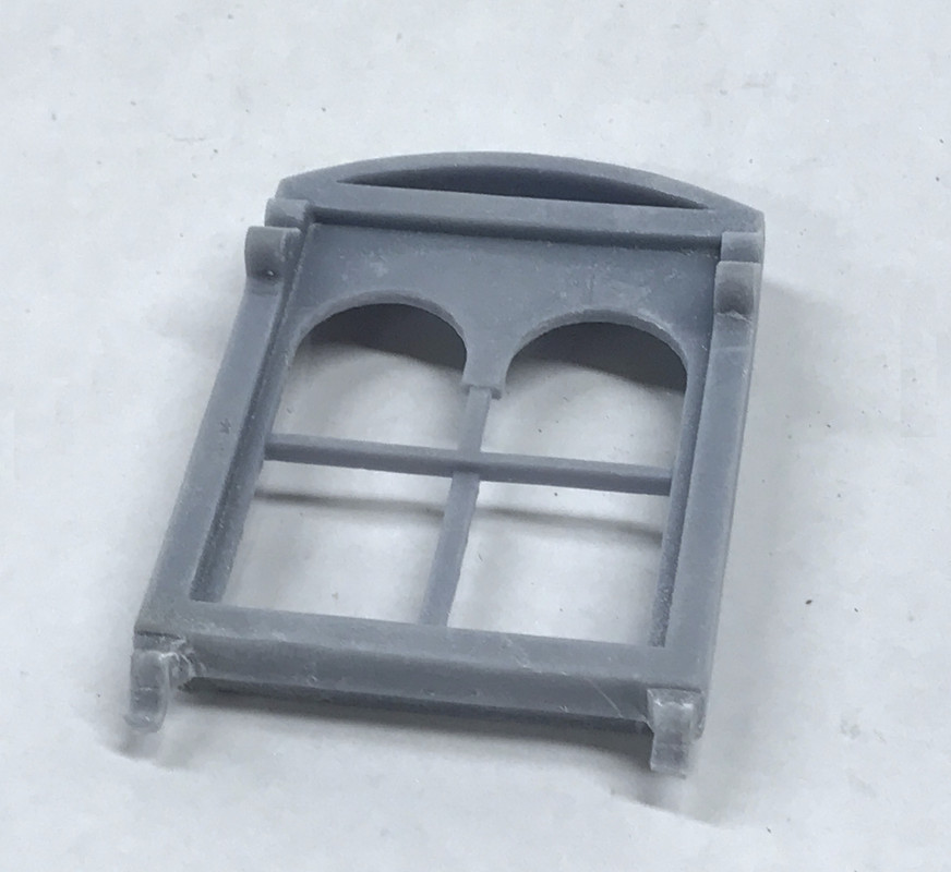
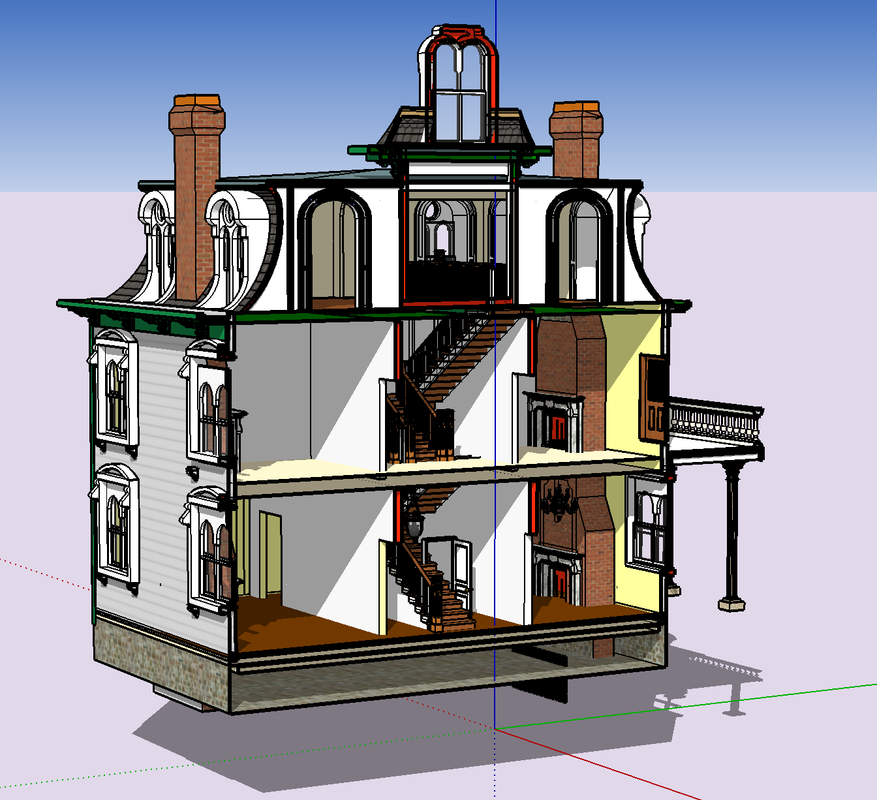
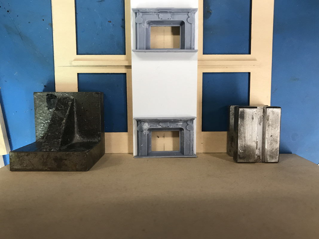
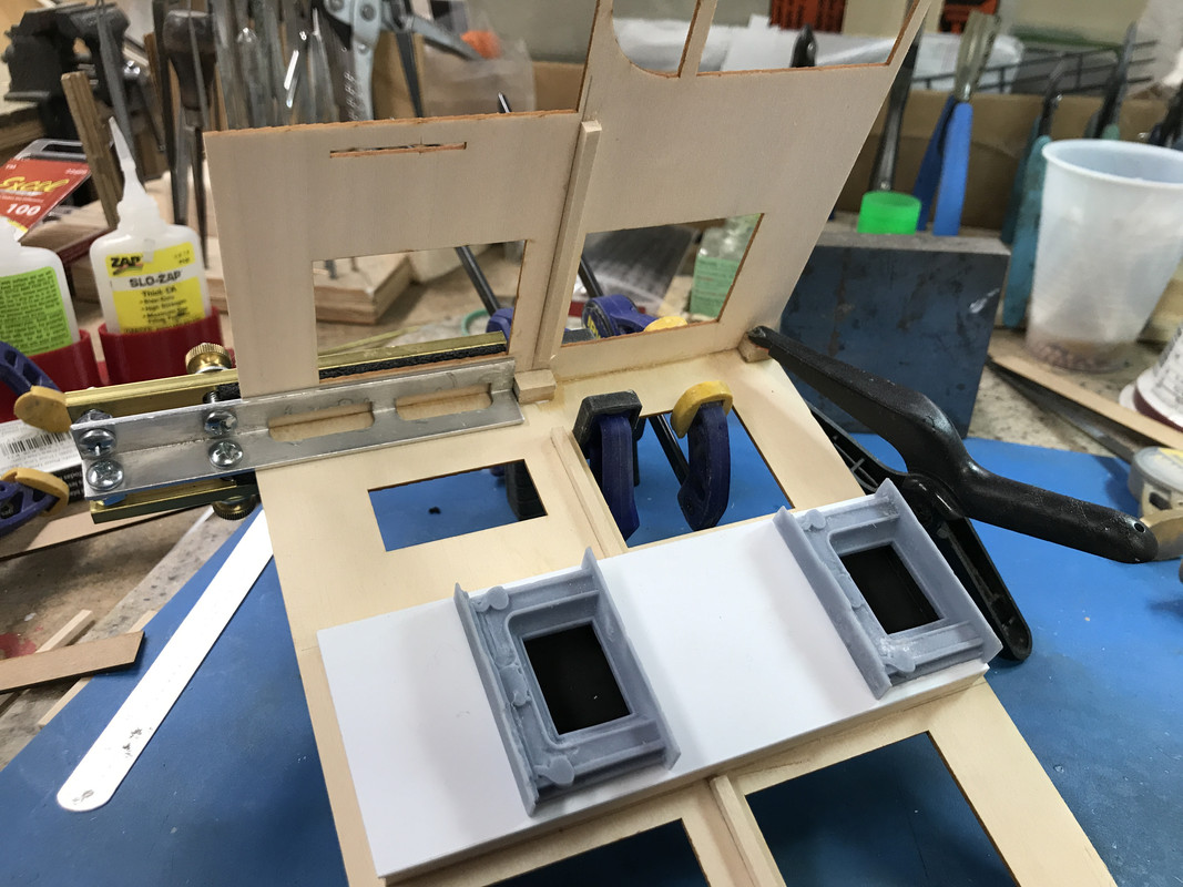
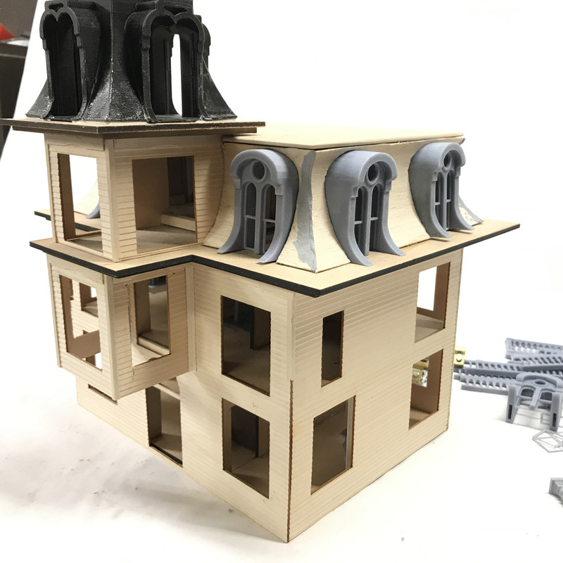
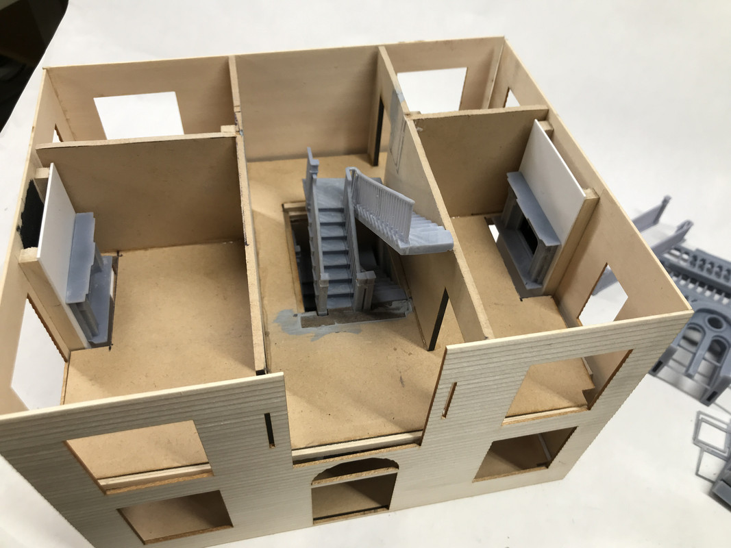
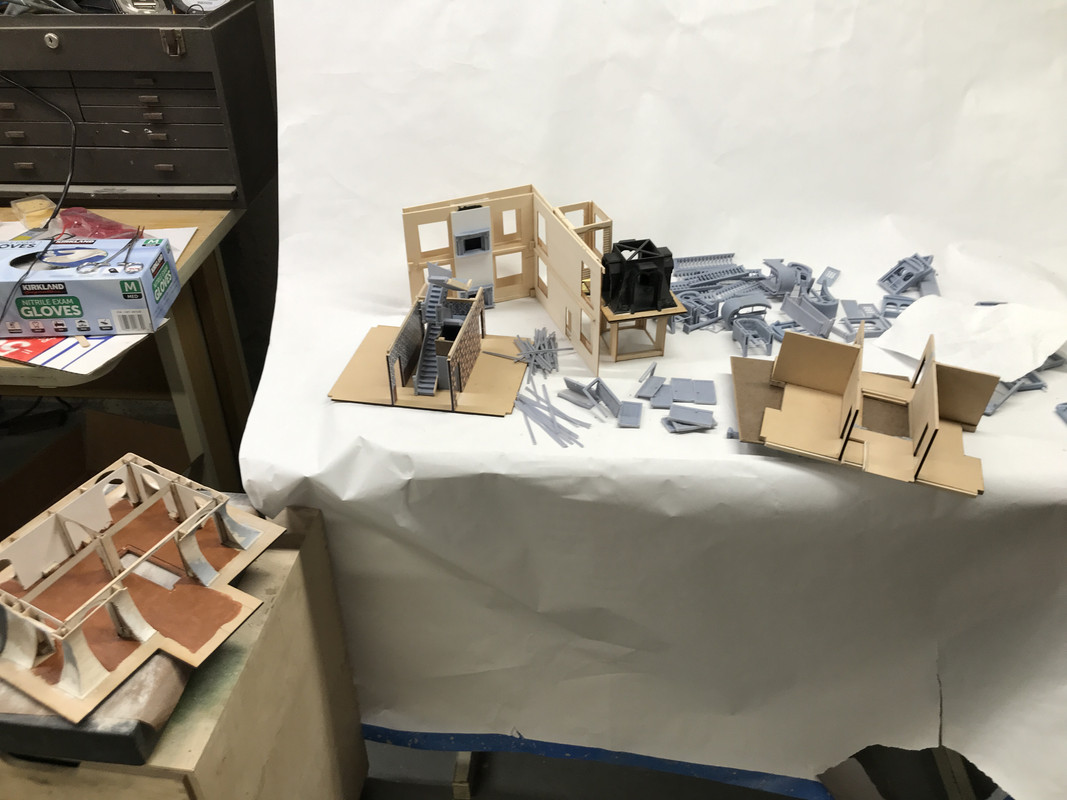
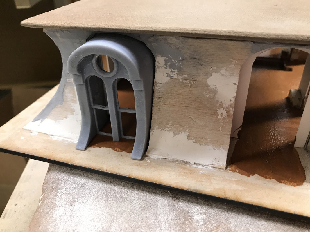
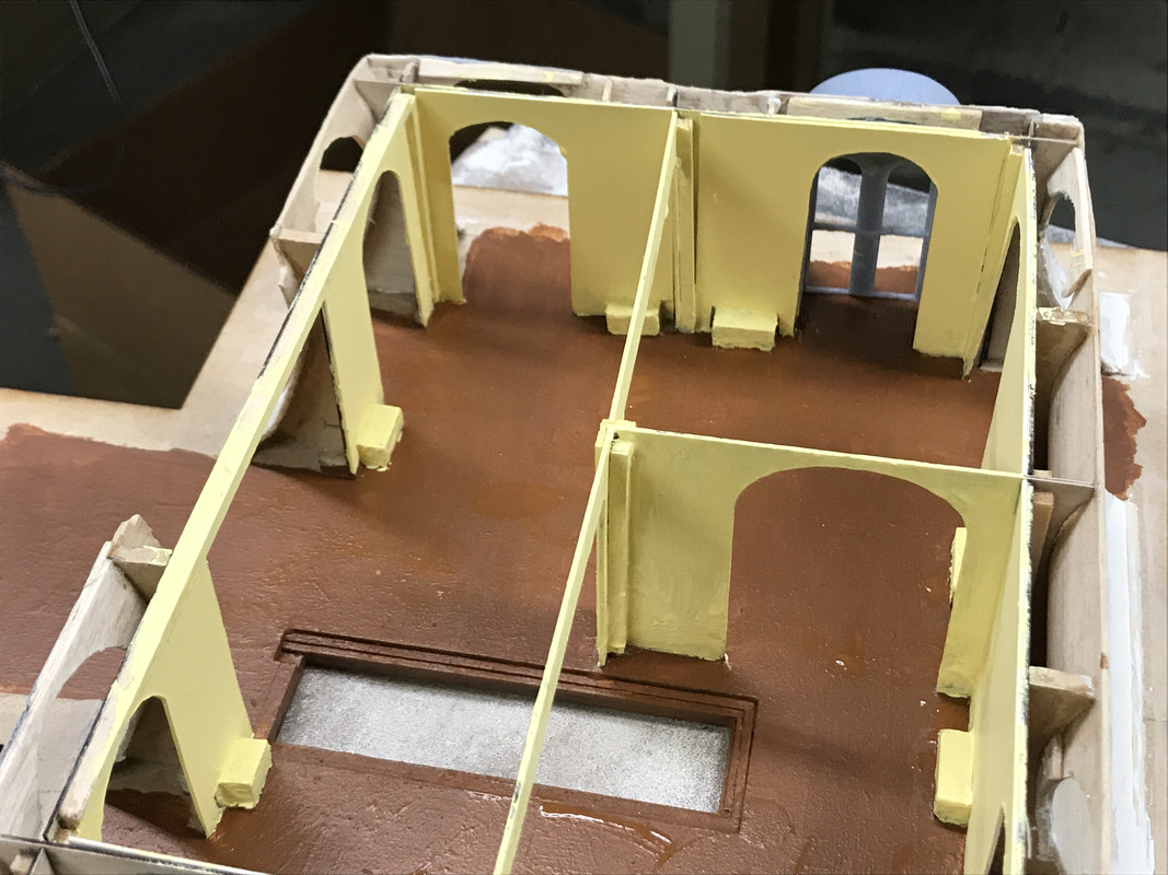
As I said, I would take y’all back to the beginning and tell the whole story. This project is as much a drawing challenge as it is a model building one. Once I decided on building another Hopper painting and chose this one, what I was presented with was a series of drawing challenges. One of the most essential were those characteristic Mansard windows. They make the building and if I couldn’t draw them, I couldn’t print them. And if I couldn’t print them, there would be no model.

What follows is a lot of information about 3D Printing. If you’re already up-to-speed or not interested, you can skip down to the bottom. I think it’s germane to this project as a whole, since so much has been created on the printer and more time was spent producing those parts than building the structure itself. 3D printing has changed the modeler’s question from “How do I build that?” to “How do I draw that?”. If I can draw it, I can make it.

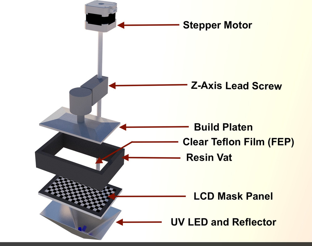
I’ve been 3D printing since June of '19, when the price of high resolution resin printers dropped from over $3,000 to $350 or less (much less). The reason for this precipitous drop was the mergining of the cell phone LCD screen and some UV LEDs to the resin printing process. Up to that point, resin printers employed either lasers to draw the object in the UV curable resin (very expensive) or DLP video projection to create the layer images in the resin (just plain expensive). Then along comes some innovators who created the layer images on the LCD screen and illuminated it with the UV LEDs and Volia! a printer basically cobbled together with off-the-shelf parts that are produced by the millions. The price dropped, but the resoution did not. My little $350 Elegoo Mars printer can produce parts down to a layer thickness of 10 microns. That’s a layer that’s 0.00075" or four times finer than a human hair. I generally produce parts with layer thickness of 40 to 50 microns.

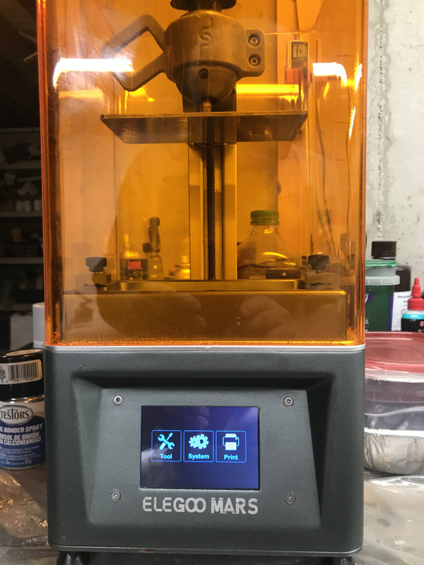
The orange cover blocks ambient UV light from curing the resin in the vat at the bottom. Elegoo has just come out with the “Saturn” model which is about 2.5X the volume of the Mars. The resolution of the Mars is actually a bit better. Besides the vertical resolution which is controlled by how fine the Z-Axis stepper motor can control, the lateral resolution is a result of the pixel density of the LCD screen. The Mars has a 2k screen which gives a pretty fine horizontal resolution. The Saturn uses a 4K UHD screen, but it is 2.5X the area, so the actual resolution is a slight bit less.

You may be familiar with the more common Filament Deposition Printers (FDM) which I call “String Printers”. FDM machines work by melting a polymer and extruding a thin string of molten polymer into a pattern driven by X-Y-Z stepper motors. It resembles the process used when decorating a cake. These are seen at all the Maker Fairs and almost every school has them now. FDM machines have their place, but it’s not producing parts in our model making scales of 1/32 and smaller. As each layer of string is deposited there are visible lines like a tiny log cabin being built. For 1:1 parts, FDMs are quite useful. FDM machines’ lower limit is about 50 microns, but they’re very temperamental at that resolution. Generally they print layer thickness over 100 microns (1/10th of a mm). At that resolution in 1:48 you have visible layer lines that need fixing.

Resin printers work by creating an image of pixels representing a layer that needs to be created in the resin. The UV light cures this resin on an aluminum build plate. The exposure time varies with the layer thickness you’ve chosen and the type of resin you’re using. My exposure times are between 8 and 9 seconds per layer. Where the UV light illuminates the resin partially it hardens and then the build plate rises to break the seal between the last cured layer and the clear teflon film that seals the liquid resin vat from the LCD/UV light system that lies directly below. The build plate then returns one-layer-height above its previous location and the process starts over, only this time, the LCD projects the image of the next layer. This process repeats over and over again until the completed object rises out of the vat, like magic. The curing is partial so the next layer will stick and blend with the previous layer.

That was a very simplified explanation of what you need to know to make successful prints. There are many variables. The same is true for string printers. They are not fool proof. Resin printers are neither.

After the part is formed, you must wash it with 95% isopropyl alcohol to removed the layer of uncured resin that comes out of the vat with the part. You then have to cut off any supports (more about this later) and then fully cure the part in a UV chamber. Mine is a UV light array bought from Amazon mounted through the wall of a cardboard box lined with aluminum foil. I also bought a AC powered turntable to evenly illuminate the parts. I have the UV light and turntable powered through a digital timer. I generally post-cure parts for 15 minutes. Before I got the timer I over-cured some parts. They turn brown and get as brittle as glass.

Print Success Variables:

The first varialble are the first layers. These first layers must stick to the build plate, and stick hard. The most common failure is the object not connecting to the build plate at all or failing to adhere sometime later in the print. I was having problems with this and finally resorted to pre-coating the build plate with a thin layer of resin and curing it for about a minute in my UV curing box.

The build plate (z-Axis) must be able to pull the forming part off the teflon film so new resin can backfill into the vacated space to create the next layer. There is suction created between the formed part and the teflon. This suction can be very strong. When the suction exceeds the build plate adhesion the part will stick to the film and the print fails. When the part can’t be lifted the next layer doesn’t form since no new resin can displace the previous layer. It’s quite frustrating. One of the strategies is to print the part on an angle that minimizes the surface area contacting the teflon.

Resin printers have only one moving part and that’s good. It’s an optical process. The Z-Axis is driven by a stepper motor through a precision lead screw. I experiemented with different Teflon films to find the one that works best most of the time. The only mechanical adjustment is ensuring the build plate is parallel with the Teflon film. This is done by bringing the machine down to the base 0 position with the build plate set screws loosened. When the plate settles in, you lock the screws. That’s it! It’s so easy to set up, that you’re printing within 15 minutes of unpacking the box.

The other print variable is the support scheme. This is a bit arcane so bear with me. For an object to form every part of it must be anchored back to the build plate. It makes sense that if you can’t lift any previously cured resin off the teflon, the next layer can’t form. With simple objects having no overhangs, you just orient the object straight up on the build plate. But many complex parts have overhangs and edges that may start to form before the object connecting it to the whole has formed. These non-forming entities are called “islands”. There is software to help identify where they are.

You draw the object in 3D drawing software. I used SketchUp. There’s a free version that’s cloud-based and an expensive pro-version. I’m using a client-based free version that Trimble stopped supporting three years ago. The 3D printers can’t interpret 3D drawing program output. They need to be converted. But that’s not all. These converted draw files need to be sliced. They need to be broken down into individual layers so the printer can create them. This is a two-step process. First the SketchUp drawing is converted to an STL file. This is a conversion program available for 3D software programs. There are two meanings for this acronym: Standard Translation File or Stereo Lithography File.

The STL File describe in explicit detail the outer surface of the object. For the STL file to render the object, the object must be a solid. This is a specific term used in 3D drawing. It means that if you filled the object with water, it would not leak out of any space. It means that all surfaces and edges are connected with no gaps. Any surface not connected is seen as invisible to the STL converter.

This is what the part looks like in the STL display. In this image you see that something’s wrong. It appears that surfaces are missing. As you’ll see, this is the result of non-normal facing surfaces present in the origianl SU drawing.

It gets worse. Not only must the object be “Solid”, but it must have all “normal facing surfaces”. This one trips up a lot of designers. In SketchUp you can draw a face with it’s outer surface facing outwards or it’s inner. The outer surface is considered “normal-facing”. You can push or pull an object while drawing it, and depending on which way, will create a shape with inside or outside faces on the outside. STL converters do not recognize wrongly facing surfaces. They are invisible. So there are two factors that make a 3D drawing unprintable. This is analagous to pulling on your socks one way and having the outside facing outwards, or pulling from the other way and having them inside out. Inside out faces DO NOT PRINT.

The slicer creates the actually machine file that commands the printer to generate each layer. The slicer shows images of the part as it will be when formed. You can manipulate this image to position it at angles and add supports where needed. It also shows any unprintable surfaces. They just image as black holes. You have to pay close attention to all these aspects to create successful objects.

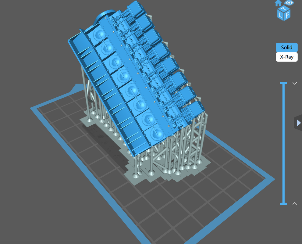
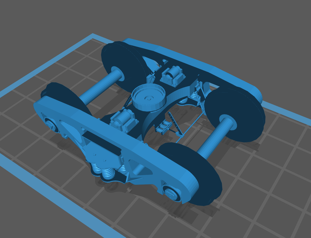
Here’s a screen print of what you see in the slicer display showing the forest of supports needed to successfully print the part. This is one half of a model locomotive diesel engine. The object is printed at an angle to reduce the contact footprint which helps to prevent the vacuum suction from pulling the object off the build plate. In the printer, it prints upside down so as the part forms in the resin it is being pulled upward. When printing highly detailed parts such as this half engine, I also have to spend a lot of time ensuring the supports aren’t attaching to any delicate details, like those pushrod tubes. Small details can be destroyed in the process of cutting off the supports.

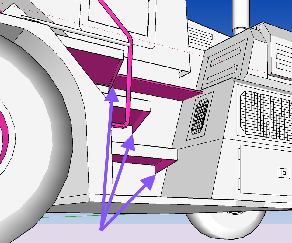
Many of the objects I create use drawings downloaded from the SketchUp 3D Warehouse. Some these drawings are gorgeous, but unprintable. The artists were drawing with the goal of creating a nice looking drawing, but weren’t concerned with 3D printing. When downloaded, I turn off the color and set SU to show any reversed faces in bright, hard-to-ignore, colors. I quickly find what editing needs to be done.

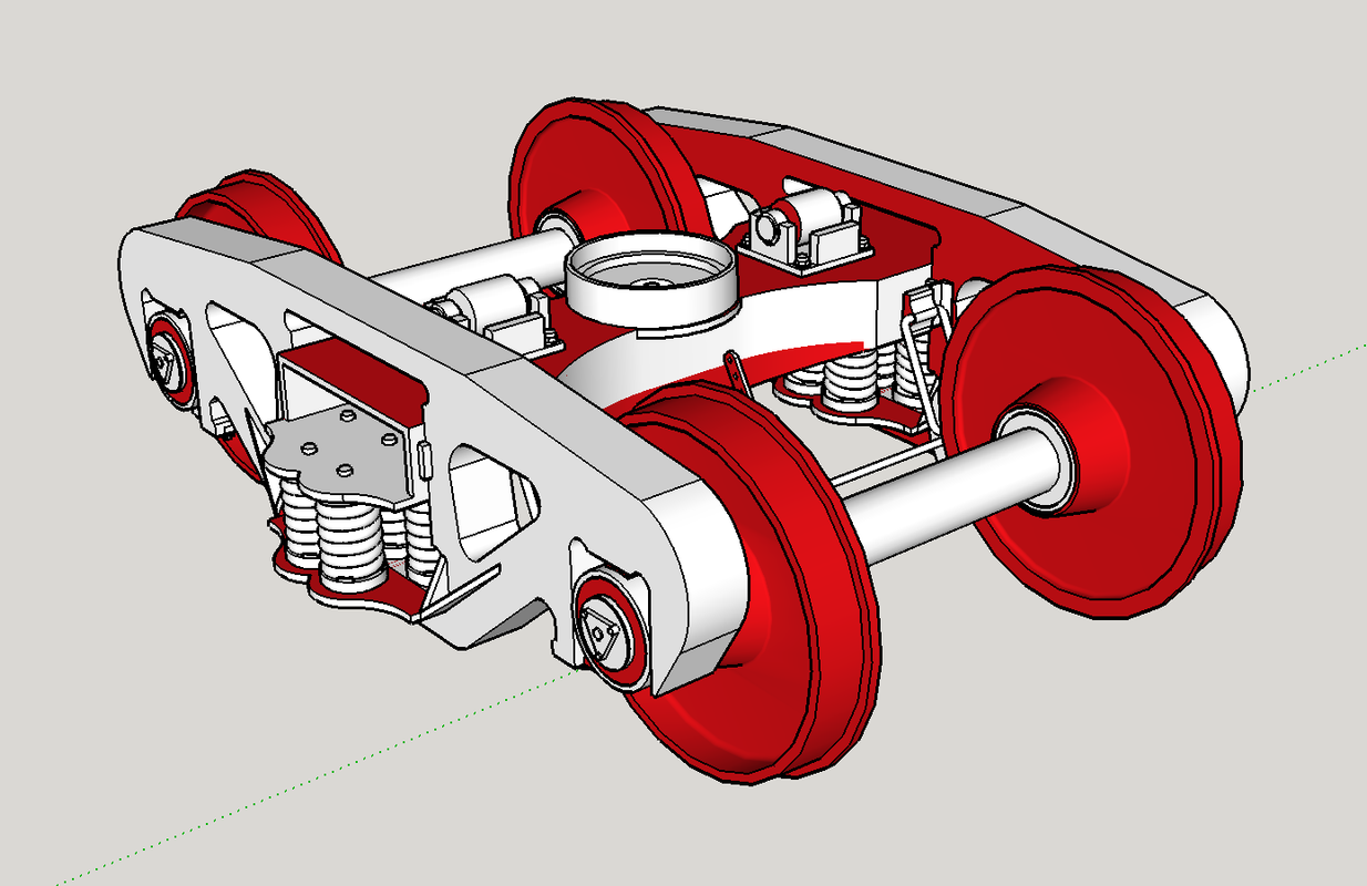
Everything in this drawing that’s bright red shows a reversed face. None of this would be seen in the STL converter and thusly, nothing would be seen in the slicer. I you refer back to that STL image you can see all these red faces showing up as invisible surfaces.

When a reversed face is brought into the slicer, the missing surface shows up as black. None of these black faces would print. I you put it in the machine it would look like something coming from a failed transporter transmission on Star Trek. It would just be a mess.

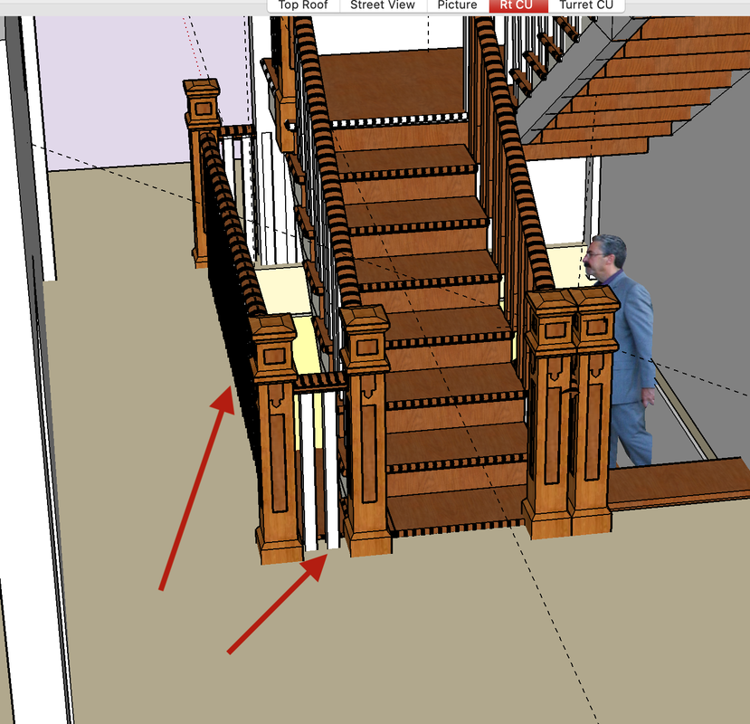
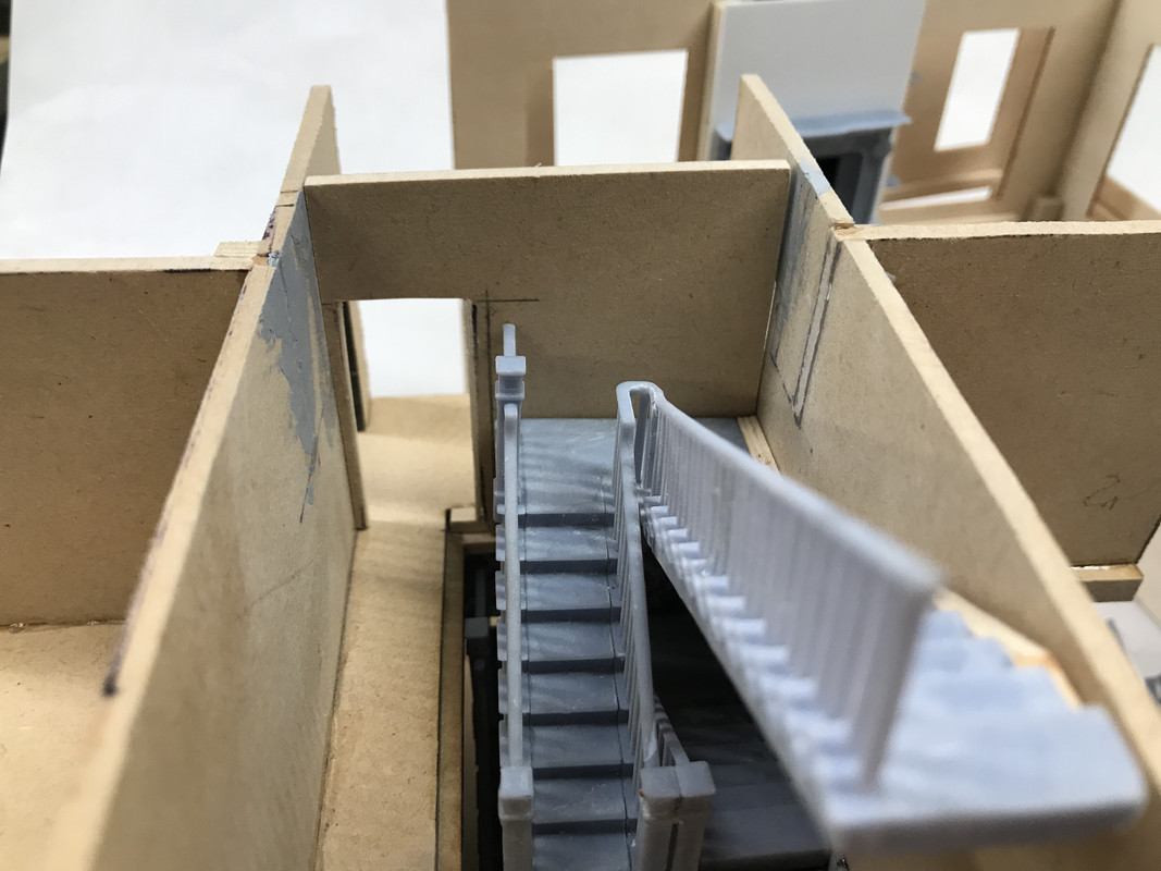
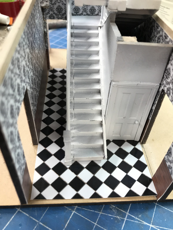
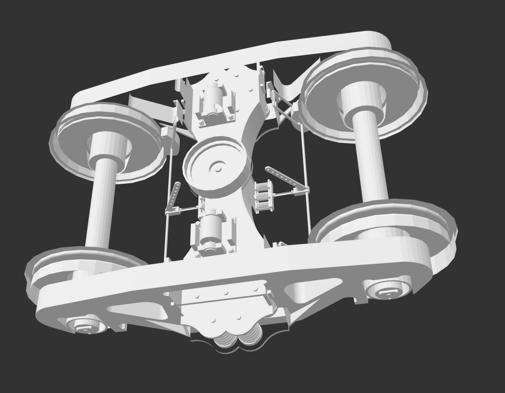
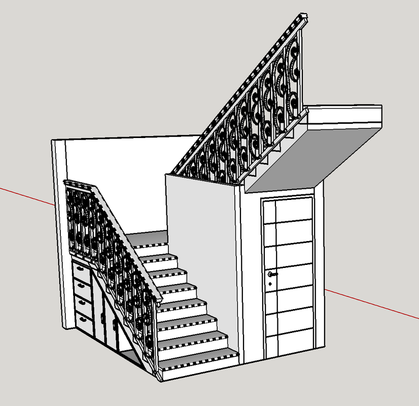
If you buy or download complete and tested STL files you don’t have to worry about any of this, but if you plan on developing your own images or download drawing from the SketchUp Warehouse, you need go be prepared to do some more work. That railroad truck with all the reverse faces was downloaded that way from SU. Some of the drawing take many hours of editing to prepare them for printing. This is what happened when I downloaded the basis for the elaborate staircase in the House.

While I could have custom-drawn an entire stair case, I always choose to download rather than draw from scratch if possible. It can save a lot of time. In the stair’s case, much had to be modified… almost everything.

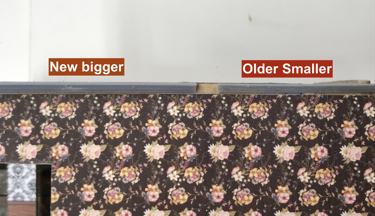
This is what I downloaded. At 1:48 there are some other considerations. Note: this screen capture was taken AFTER I had corrected all the reveresed faces. An unsupported surface much thinner than 3/64" ends up being too fragile to exist in the real world. So those wrought iron rail spindles, while very attractive, would be a disaster. The printer would attempt to resolve them, and probably could print something, but they would shred in trying to remove them from the build plate. I had to come up with another design.

I went to a turned spindle and printed two attempts. The first was pretty scale (read that too thin) and they didn’t hold up at all. The second attempt was a little better, but wouldn’t produce a reliable job. I finally came up with a very plain square spindle that would be correct for a house of lesser opulance, but it would have to do. The difficulty arose where the spindle curves ended up created islands that required supports directly attached to them. While removing these supports a large number of spindles ended up destroyed.

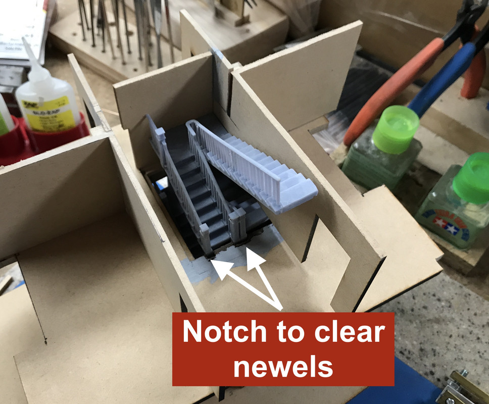
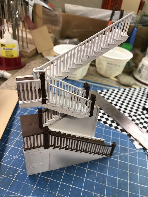
Then I needed to add another full flight, and develop turned railings at the inside turns, new newel posts, change the run lengths, and adjust the tread widths from the 2nd to 3rd story. In other words, I practically had to redraw the entire stair.

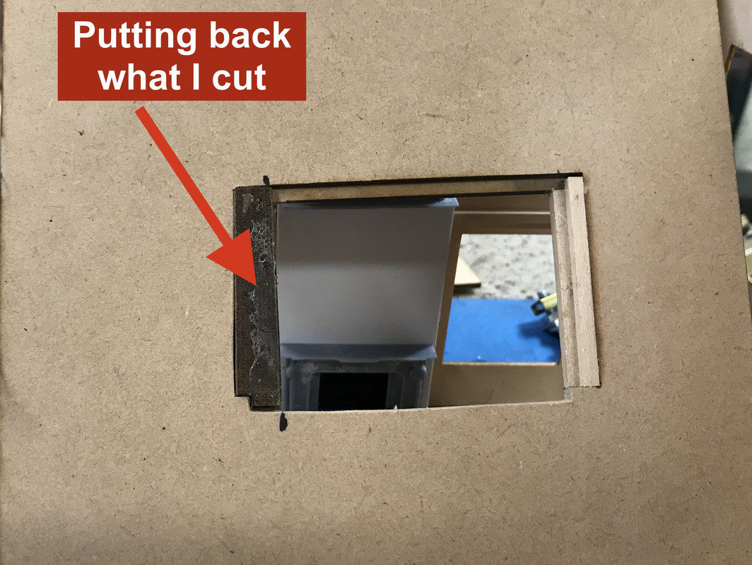
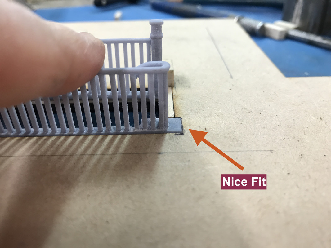
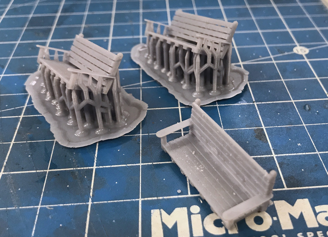
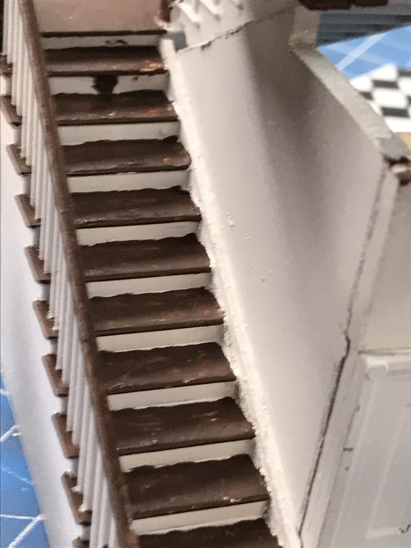
This is what I ended with. This print is 11 parts. In order to print the stair treads AND railing connected, I couldn’t print the entire stair. I required supports on the spindles. I ended up dividing the tread portion in two with a short section holding the spindles and railing, and the other making up the tread remainder. These were then glued together with CA. CA cures very quickly in the presence of the resin.

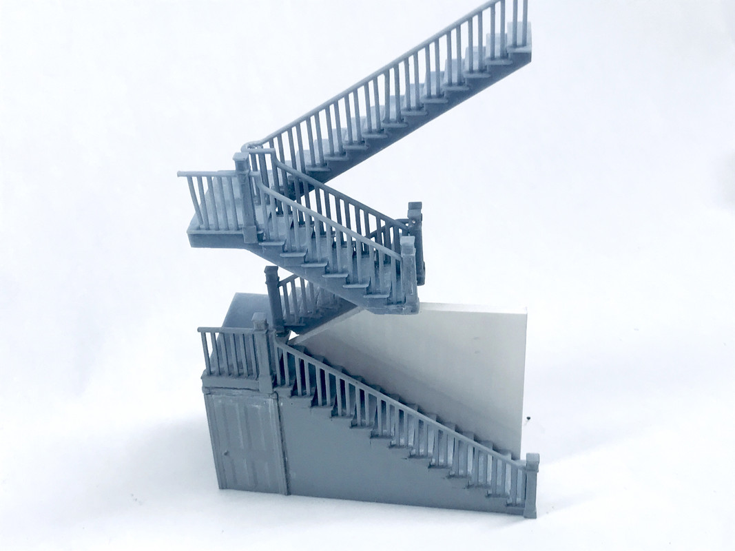
The other material used in finishing the prints is Bondic. Bondic is basically a higher viscosity version of the same UV resin of which the part is made. It can fill holes and join parts like welding and cures in five to ten seconds with the little UV LED that comes with it

This is a lot of information for the first post, so I’ll stop now and see who’s watching. The story will continue…

Thank you for taking the time to go through the process. That’s the clearest explanation of 3D printing I’ve seen to date.

Looking at various computer renderings of printed parts on the Shapeways website, I’ve always wondered at the elaborate lattice of ‘support’ structures beneath. I obviously realized it had to be a generic outgrowth of the printing process…but this is the first time it’s clear why.

(I may not be the brightest crayon in the box to start with. [whstl])

By the way, I think we’ve all ‘lost’ long post texts at one time or another. Many of us have taken to composing lengthy ones elsewhere, then pasting them in. Just one of the several ‘joys’ of this…ahem…cutting-edge forum architecture.

Looking forward to the next installment.

Thanks for the positive feedback. With one person responding I will continue the journey.

I can’t emphasize enough that 90% of printing success takes place in the design and slicing process, not on the printer. The printer’s just the final act. Yes! Things can go wrong directly in the printing process, but much can be avoided by designing for printing from the get go. This imposes some restrictions on the concept. While printers can resolve a nit on the nut of a gnat (to quote my dear father), the part may not be viable. I found when printing miniature work tables, that the broad, flat table tops had to be a 1/32" thick or more to have enough material to not end up as a fragile as tissue paper.

UV curing resins come in many varieties. It’s about a 25 year-old technology and a lot of work has been done. You can get resins that are actually UV curing investment casting waxes enabling jewelers and dentists to go from computer design to wax master to precious metal final products. The “normal” resins are brittle when cured. If you drop the part, it will shatter. Ask me how I know. Now there are high impact resins that have more toughness. These extend all the way to completely flexible resins. And you can mix flexible resin with more brittle varieties to make your own blend.

The downside of more “rubber-like” the resin is longer the cure times between layers. It’s tradeoff between brittle/flexible and short/long cure times. With a 1,000 layer print (not unusual), 8 seconds exposure time (UV LED light on time) is an 8,000 seocond print time, about 2.2 hours. Make that a 15 second exposure time and you’ve doubled the print time. Additionally, the more rubbery resins have a higher vicosity requiring a longer dwell time when the plate rises to permit new resin to flow underneath. This higher viscosity may also require the resin to be warmed beyond room termperature needing a heated vat or other means to raise the temperature. In other words, it ain’t that simple. My goto resin is Elegoo’s ABS-Like Standard. It was an improvement over their earlier standard and has some reduced brittleness, but it’s not rubbery by any measure and will still shatter when a part is dropped.

Reversed faces are not the only bugaboo that you need to repair before creating a viable drawing. I wanted to create a heavy-weight forklift truck for my O’scale engine house. I found a great drawing on the SU Warehouse. It was very realistic and would make a great model. There were problems. Of course there were the reversed faces, but more importantly, most of the surfaces had no depth. The artist was drawing sheet metal surfaces as single planes. Looked great, but can’t exist in our 3D world. Surfaces without thickness cannot exist outside of the world of 2D geometry. Even something as thin as a sheet of paper is 0.003" thick. Everything has thickness.

This was the first evaluation of the drawing. Magenta = reversed faces = unprintable.

Then I found that all the sheet metal chassis parts were drawn as single planes. Every surface has to be modified to add thickness, and not just any thickness. For a broad surface to have enough strucrtural integrity to be usable, as I noted above, it has to be greater than 1/32". The redraw took hours and hours.

Look at these foot steps. See the downfolded edges? They are single planes. They have no thickness and WILL NOT PRINT. This occurred in many places on the model. In the main body parts as long as the object was a solid, have all of the edges connected to one another, it would bring as a block. The body was not a solid and spaces had to be closed to create one. In fact, I did print the entire body, minus cab, as a single part. Even though the printer could print the handrails, I eventually replaced them with phos-bronze rod. I also replaced all hydraulics with scratch-built brass units.

Sometimes it’s better to print things as subassemblies and the fork lift was no exception. I broke it into useable pieces that could print without too much support rod destruction. And my little printer has a pretty small print volume, so there’s that. This was my first attempt at the parts breakdown. I ended up placing additional cross-bracing between the cab window pillars so they wouldn’t warp. I also thickened every surface in the cab so they would withstand printing and handling.

I tried to print the fork as a single assembly, but it was unsuccessful. I changed it too look like this. As I noted, eventually, due to poor print results, I replaced all the hydraulics with real metal. Sometimes, the best thing to simulate metal is metal.

The final print scheme had me combining the engine cover and the remains of the body as a single part. I did have to go back and do repair where printing was sub-par, but the end result was worth it. The engine being carried is also a 3D print project. I made my own decals as well.

That’s enough general info about the 3D printing process, so let me bring it back to the House project. As I noted, it was the Manard windows that was the critical path in building this structure. The Mansard windows have curves going in two directions. There’s the main arch that penetrates the entire window and then secondary curves on the side panels that blend the shape into the roofing. When the window was a solid shape with the arched top, you can punch through the inner-arch, but then you can’t push through the side arches since they’re going through a penetrated space.

In this instance, you create a round cylinder the radius of the side curves and intersect this shape with the window. If you have SU pro, it has a boolean tool set that lets you add or subtract shapes together and you can subtract the cylinder’s volume from the window volume leaving the curved shape behind. I have the Free version. To do shape interaction with my version is more time consuming. Here you place the cylinder into the window shape and choose, “INTERSECT FACES”. Whereever the shapes intersect leaves new lines and edges. You then go about erasing any lines and faces that DON’T LOOK LIKE WHAT YOU WANT. It’s what Michaelangelo said about sculpting David, “I just keep cutting away everything that doesn’t look like David”, (or something to that effect).

Intersecting faces this way can become very complex very quickly. It can take many minutes to carefully remove the unwanted parts of the intersection. I chose to go further with this print. I printed the window frames and mullions integral with the window frame. This would save me assembly time. I had Rail Scale Models laser cut the acetate for the windows in the exact shape to drop into the finished windows. Pre-planning all this can really help the build. The is the STL image as seen in the Mac Finder Preview.

Another 3D printing consideration is how much resin you’re comsuming. Resin ain’t cheap! I’m paying about $30 for 500g. Each part doesn’t use that much, but it adds up. The thick window walls would unnecesarily use resin and could be redesigned.

I hollowed out their backs and then put in some cross-bracing to prevent warping. Yes… thin section prints can warp.

With this modification I was able to successfully print the eight required windows and I was off to the races. Here’s the Manard window being used to cut the openings in the balsa Manard skin.

The were a ton of main house windows that needed to be printed. These were a somewhat simpler geometry but had their own challenges; those decorative drops. It took a couple of trials to position the print successfully so all the aspects would print. Once you dial in the setup, the printer will print successfully over and over. I was able to print four windows per load and did the whole print in about a week. I would start the printer at night and find the parts waiting for me in the morning. The number of parts on the build plate do not change print time. Only the height (number of layers) and exposure time/layer determines print time. So as long as all the parts fit, print away.

There is a balustrade railing that surrounds the balcony. I found a nice prototype in the SU 3D Warehouse, and was able to use it almost without editing, but it did need some. Again, there were reversed faces and I had to create lengths that could be combined to make a contiguous railing. The porch columns did warp in some cases, but they’ll probably work.

Inside doors were more challenging that I expected. In fact, I just redesigned them last night and will print them today. They were too thin for the wall thickness. I wanted an up-scale door frame with bullseyes in the upper corners. I attempted to print them with details on both sides. One side had to have supports and in removing them almost obliterated the upper details including those bullseyes. I made a field repair by cutting off the top frame and just reprinting it with good bullseyes. This solved that problem, but they were still too thin. My re-design has the doors being printed in two halves so I can print them flat on the build plate. This way both sides will have perfect detail and I will join them as a post-print operaton.

I also expect that any warp will be cancelled out when I join the two door faces back-to-back.

All in all I printed close to 100 pieces over several months in preparation for the project. Meanwhile, I had the flat parts laser cut at Rail Scale Model. In the interim I was building the Typhoon and the Sherman. The printer works unattended so it’s producing something while I’m producing. Resin printers when they’re lined out work better independently than FDM printers. When you’re messing with molten plastic extruded through a heated nozzle and three stepper motors, more can go wrong than a basically optical process with one stepper motor. It all depends on the drawing and the setup.

The only part I did not print was the large cupola casting. It was just too big for my machine. I had this done at the University of Louisville’s Advanced Manufacturing Institute, one of the most sophisticated in the USA. It was done on an FDM machine and has the characteristic thread lines. They will not be a problem on the curved Manard roofing portion since they’ll be covered with shingles, but I may have to fill the frames if the lines are too obvious.

Notice too I printed four fireplace faces, a few sets of window frames that will be in the open position, and those chimneys. Due to their length and height, I printed the chimneys in four sections, again, vertically directly connected to the build plate so there were no supports to cut away. When I tried it in a more normal approach the supports destroyed the mortar lines. I glued the sections together with CA. The bag contains the paired corbel sets that go under the eaves. This represents a huge amount of work!

That’s enough for this session…

I have a love/hate relationship with SU.

This is probably based in too much experience with other CAD software (notably AutoCAD).

I have a hihgly jaded veiw of the various models of things out there, too. (I can build a better REVIT family of a Component than I can download, at better than 8 in 10; I’ve been selling ACAD blocks for decades now.)

I’ve been to some of the RP wars, too. It seems like only yesterday that resin STL printers were around $60,000 and you needed an entire garge for all the units.

The new, inexpensive resin printers have definitely caught my eye (much abetted by Luke Cowen and Kathy Millet).

Seeing large scale results is very promising and encouraging.

Here’s a good example of several things. First of all, having your own machine lets you redo things that you don’t like. Buying from Shapeways, while feasible, is expensive. You don’t want to have to do things over. One small print at Shapeways is $40.00. That’s the cost of a entire bottle of resin. Another thing is that you can always do something better. And lastly, rethinking the scheme can produce better results.

Here’s yesterday’s example.

When I first printed the interior doors I chose to print them as an entirety with both front and back detailed. This required support regardless of how I attempted to support it. If I printed it sticking straight up and down door knobs, some overhanging trim edges and the characteristic bullseye had islands and supports needed to be run directly to them. These were very delicate details and and support removal would damage them. If I tipped it over at an angle, then even more supports would be needed. I chose the best compromise, but the support removal damage was so servere that I had to saw off the top frame with the bullseyes and print that part separately flat on the build plate, and glue it to the previous print. The results were still sub-par.

This image is of the less detailed back. There is no carving on the door frames.

The impetus for the change was the bad batch didn’t fit the space like I wanted. The frame was just the wall width, but I wanted the trim to project a bit. This meant a redo. So if I’m going to redo it, then why not make it better.

I woke up on Sunday reimagining this problem. I do most of creative thinking in those moments of approaching lucidity in the morning when just waking or when I’m staring at my steadily aging face in the mirror when shaving.

Instead of making it in one piece, if I split it in two with matching back-to-back pairs I could print it flat on the build plate face up with no supports at all. No supports means no clean up.

Since I wanted it to be thicker anyway, I was able to make each half with enough material in it that I would have a decent print. And since they were going to be glued back-to-back, all the warps would be in one direction so when glued it would cancel out.

The results were exactly what I wanted. Printing flat meant that each print only took 26 minutes. Remember, print time is directly related to how tall the object is, not how wide since the entire layer prints at the same time. In FDM printers print area DOES affect print time directly since the string is laid down one at a time. More string equals more time.

I was able to put four halves on the machine at a time.

Here’s a comparison between the old and new design. This first pass failed on the door knobs. I redrew that aspect and printed it again. This time it was successful.

Here’s the new design in the wall. I don’t know about you, but that’s a nice looking Victorian era door. Laying on the floor is my first baseboard design. That too is going to be reprinted with a new thicker and taller design. I may do some crown molding, but that would be crazy, wouldn’t it. I’m also making some sets with frame and door separate so I can pose some of them open.

I have an SU plug-in, Profile Builder, that gives you hundreds of millwork designs for everything: chair rails, baseboards, crown molding, etc. It’s not a free program, but it’s worth it if you doing architectural work. It didn’t take long to find another base design and further modify it for 1:48. At this scale you have to exaggerate certain aspects so it will print well. In also building modern plastic kits, they are now able to mold some incredibly thin cross-sections, but even then, some of these parts are so fragile, you end up with a kit that you can’t pick up without breaking something.

I custom-built industrial models by hand years ago, doing my own masters for complex parts and then making molds to cast them in resin. The leap from that era to this is barely imaginable…like going from the Flintstones to Star Trek.

Once again, most appreciative that you’re taking the time to post this whole process! Enjoying it immensely…reading every word…and learning a great deal.

Sorry, I would have responded sooner but I wanted to read everything before I commented.

Oh wow, that’s amazing Builder. Nice rundown on 3D printing, I’ve read about it, and sorta understand the rudiments of it but nothing to that detail.

I wonder if you could 3D print that insane spiral staircase from ‘The Haunting’ now…

Thank you for following along. Since this project is about 3 weeks underway, I’ll be going back to the beginning, but not providing the level of detail that I would do if posting it in real time. Once I catch you all up, I’ll be posting in more detail.

You could probably do a spiral staircase, but it would have to obey the limitations that I noted yesterday. If the members are too frail the part will either fail in the printer or fail when you try to clean it up. It would have to be printed in subsections that could be properly supported. I’ve thought about doing one for the turret, but chose not to make this beast any more complicated than it already is.

It’s time to talk about the building itself and the design ideas. SU enables you to display the model on the screen in a number of ways including sections. You can take a screen print of all of these. I have a bunch pasted on the parts-catching walls I’ve added to prevent small parts from entering the dimensional rift.

Here’s a section view of the house. You can clearly see the staircase and the fireplaces. There are four fireplaces with the same hearths in all four locations. The hearths are set away from the wall which would be the chimeny chase. My fireplace location is different than the Hopper painting. I couldn’t figure out where to put his fireplaces based on my floor plan, so I took some architectural license.

In my actual model I did not build out the fireplaces as much as you’ll see. My rooms just aren’t that wide.

Work began with some planning… and I’m not done yet. I didn’t want to erect all four walls yet since I wasn’t sure how I was going to handle the floors. The first floor plate sits inside the walls. Below the first floor plate will be a faux stone block 4 scale feet high. The porch is at the first floor level and I have laser cut traditional lattice for the front bottom of the porch.

I used 1/8" square stock for corner reinforcement as well as some selective pieces of 1/4" square basswood. I didn’t put full length pieces in, just long enough to give some corner reinforcement while not being too obtrusive. I had to notch the base plate to clear these blocks.

The second floor plate is two layers of 1/8" MDF. The reason for the lamination is two-fold. I wanted to give a reasonable scale thickness of 1 scale foot for floor thickness and I needed to provide relief for the bases of the stair railing. I wanted the spindles to come out at floor level. This necessitated dropping the rail base about /18" below floor level. This complicated the design and laser cutting, but I think it’s worth it. This detail drawing shows a place where the rail sits at floor level.

I used Titebond II wood glue to hold the big pieces together. Normally I used Aleen’s Tacky glue for all the wood stuff and then often add some thin CA to lock it together without too much clamping. The Aleen’s then can dry at its leisure without the joint falling apart. I used styrene sheet for the chimeny facing. I was just easier for me to use it since I didn’t have the right kind of aircraft ply and didn’t want to make a trip to Scale Reproductions, Inc. just for that.

The fireplace walls were glued so the hearth front drops over the first floor plate. I had to notch the second floor plate to clear the fireplace entirely since this was going to dropped down from above and was ending up below the second floor fireplaces. To ensure that the fireplace sat correctly on the first floor, I held the floor plate up against the side wall while gluing the fireplace unit in place. This image is looking straight down. BTW: I got that spiffy hearth design from the SketchUp 3D Warehouse.

I decided to glue up adjacent corners and then wait until I complete the entire shell. I chose to do this since I’m wallpapering all the interior walls and it would be much easier to do this when the walls were completely accessible. This goes the same for installing windows and any window trim. Once I’m satisfied that most of the work that can be done is done, I will make the structure whole. I used Aleen’s and CA to hold the walls together. I have some of those corner clamps that help. They’re really designed for HO structures. O’scale structures are pretty big, but they give enough support that I can work around their shortcomings.

I put together the turret walls and found that my laser cutting was off in this area. First of all, I really wasn’t sure what was happening with the mid-turret cornice. I had the turret walls cut as a two-story affair only to find out that I included the cornice in the extension of the roof plate that included the second floor of the turret. I had to split the turret walls and remove the 1/4" that represented the roof thickness. The main roof plate (attic floor) is also two layers of 1/8" MDF for two reasons. It includes the step back of the eaves and it also has the 1/8" rabbet for relief of the attic stairwell railing just as I did for the rail on the second floor. Designing this building really was a bit of architecture. There were many drawing hours completed long before I could ever think of actually building a model. When you buy a kit you never get into this world.

I also found out that my tab slots were one material thickness too wide in the front wall. This is not the first time I’ve made mistakes with tab and slot design. I don’t know what my problem is. It happened on the distillery project and again on the engine house. I’ve resorted to building the model in CorelDraw, which is where I draw my laser cut plans. Regardless, I worked around the error and even though the walls will be slightly out of square looking down, it’s not very discernible.

After assembling the turret walls I tested the window fit. I had already tested the fit on the main walls. I also started putting the upper fascia boards on all the walls. The turret windows impinged on these boards AND the side single window slots were about 1/16" too tight. The double window holes are good. I also had to relieve the fascia board to accept the curved window tops. Notice too I installed the angle trim on the corners.

That’s enough for tonight. By the end of the week this thread will be current.

That’s amazing Builder. I’ve been wanting to build a demolished building for a 1/35th diorama- I love what you’re showing us here.

My worklife started in the late 1960s as an Industrial Arts Teacher. I went from there into industrial training and ultimately to senior learning management, but I’ve never lost the desire to help others do stuff… better. These fourms on which I post incessantly, serve that purpose. I receive as much positive inspiration from the folks who read all this as I think I give them. It’s very symbiotic. I really appreciate the feedback. It makes it worthwhile. So thanks! I’ve been posting the entire railroad build in all its gory details on the O’guage Railroading Forum since 2012. I have readers who’ve been following it for years. It’s a tough audience and I have keep upping my game.

I left off with the wall assembly. The stairway was a connudrum from its inception. I was never quite sure if it was going to fit as I thought. To have the first flight starting where I wanted it to I had to lengthen that flight and shorten the flight from the landing to the second floor. The first flight from the second floor to the landing was the short run and the final flight to the attic was the long run. The second flight ended with a newel post and the 3rd flight started with one, but the 3rd to 4th flight turn needed a continuous handrail. This was a challenge to draw and a challenge to print and assemble. I realized that all these pieces needed to be assembled outside of the building and inserted somehow during construction. There was no way in the world that I could have assembled them in situ.

What confounded me was the step and floor alignment. As it works out, the second floor plate had to be relieved to clear the newel post bases. I never was sure if my floor opening for the stairwells was correct, and didn’t truly understand what was going on until I had the parts in my hand. I first thought the second floor gap was in the wrong place and cut away an 1/8" off the back and added it to the front, only to find out when I got the walls together and re-fit the stairs, that my original dimensions were correct. So I reversed my mods. Like I said, I didn’t really know what was going on.

I’m getting good at making “Board Extensions” replacing stock when things are too short. Anyone can cut things shorter, it takes some real skill to make things longer. It reminds me of the famous quote by Etore Bugatti when asked why he was making race cars in the 1930s with cable-operated brakes. “Anyone can make a car stop. It takes a genius to make a car go fast.”

These were the relief cuts for the newel posts. Notice the filler to hid the “board extension”. Notice also there is a space between the narrower second flight and its adjacent wall. This week I did make a filler piece to close that gap.

The attic floor is a laminate. I glued it together and clamped it in a wood workers vise and other clamps to make it nice and tight and flat. It too has an opening for the attic flight and the attic railing. The railing recesses into the rabbet around this opening. After fitting I found 1/8" drop was too deep, so I packed it up with some strip wood. The railing and the floor now matched nicely.

While all these tiny modifications could have been built in during the laser cutting, I’m not that good. If I were cut the house again, much of these changes would be baked in. But even then, I probably would find more refinements. My hat goes off to companies like Bar Mills that knock out their very nice laser-cut structures where everythng is perfect. But I must say, they’re not including 3 story staircases, fireplaces and as you’ll see, chandeliers, baseboards and crown molding.

The cupola, as I noted, is a single piece FDM print. It has some conspicuous filament lines which I’m debating about. I may or may not fill them. The Mansard portion gets shingles (Laser-cut Rail Scale Models Victorian Fish Scale Shingles), but the painted portion may be needing some filling. I’m not looking forward to it.

I epoxied the cupola to the turret cupola floor and then went back and used some Micro-balloons and epoxy to fill the bottom seam. This open seam was the result of some warpage in the lower level. I did some careful measuring, but in looking at it yesterday, it doesn’t seem to be perfectly centered. In all the roof overhangs, there will be a ledger board on the outside so it will be the rain gutter system.

I printed pairs of the nice corbels that are so essential in this building’s design. I found on the SU Warehouse. I wasn’t sure if my eaves were big enough to hold them so I had to test. I think the test was successful.

By printing them in pairs I eliminated one headache of having to position them near each other. I printed more than I need, but it doesn’t matter. If I need more, I print more. I keep the print files. That’s the beauty of having this marvelous machine sitting at my side.

The Mansard roof is built on formers like building a wooden model ship or airplane. Having built a major RC, four-engined, 1:16 scale B-17 completely out of balsa on commission I learned a lot about using formers and skins. I specified too thin a material for the attic structure. I inadvertantly used thin ply where it should have been 1/16 minimum. This resulted in very flexible pieces that needed beefing up all over the place. Alls well that ends well and I was able to make it work. Again, if I was cutting this building again, I would fix this too. It’s almost impossible (for me at least) to draw up a complex orignial structure, have it laser cut and have it all work first try.

This view shows the formers which slot into each other by cross-lap joints and all the corner braces to strengthen it. My clue that I specific the wrong stock was the 1/16" slots that were almost empty with the thin ply. This thin stock also reduced the gluing surface area for the balsa skin that followed.

Another RC trick to get balsa skins to bend nicely is to soak the outside curve side with vinegar. It penetrates and swells the fibers on that side and makes conforming to curves much easier. I don’t screw around with any glues except CA when gluing these skins. I sprayed the contact zone with accelerator and then bathed it with medium CA. I align the piece at the bottom, hold my fingers to the top reversed curve and tack that, then move downward on the curve until the whole deal is glued. Needn’t be neat here since it’s all behind the scenes.

Where the roof met the turret wall it needed a sharp edge. I measured where the turret would fit and placed alignment lines on the balsa to cut it with a very sharp #11 blade.

One of the most challenging part of making a reverse curve Mansard is the corners. I could have drawn up corner formers on SketchUp and have done so in other projects. In this case I laid down the first roof panel extending it way past the corner. I used the adjacent former to approximate where the roof corner would actually be, and then cut it about 1/16" or large further out. Then I used a straight piece of wire lying on the formers to locate a more precise cut line and shaved it down so it was pretty close. When laying the adjacent roof piece it’s easiers since you now have the other roof’s curve to trim to.

When doing this it’s really important that the formers are positioned correctly from the start. I drew a datum line around the roof perimeter with the former set back after carefully centering the attic frame on the attic floor.

Again, I let it extend out past and then shave it back to coincidence. Filler makes it all pretty.

After all the skins were in I had to open up the skin to accept the Mansard windows. This was another challenge. Since the roof curved out so far at the bottom I couldn’t simply hold the window up to the roof and trace it. I needed to open the roof some so I could push the window in deeper.

I used the #11 blade held parallel to the plywood former behind the skin. I punctured a few places on the vertical portion…enough so I could visualize the line. I used a small square and then sliced all the way to the roof base and removed the scrap. I then pushed the window in as far as it would go and trace-cut the curved top portion. My first attempts were crude and left me with large gaps. I got better as I went along.

I tried in all the windows after the cuts were made and the building was starting to look like the picture. This image shows the too small roof plate.

There are gaps at the edge of the lower roof panel where it meets the main roof. Last week I went back and glued some 1/16" square basswood to the roof at the gap. I then shaved these pieces down so they approximated a smooth transition, sanded it with a rubber former and sand paper, and ended up with Tamiya Fine Filler. I still have to do final sanding on all this.

Lots of filler. Filler is my friend. This view also shows the packing around the opening for the attic stair opening.

The upper roof plate was supposed to extend out past the last Mansard curve enough to afford a smooth reveresed curve transition. My laser cut roof didn’t do this. It was about 1/8" too narrow in both directions. I had some 1/8" Masonite laying around and cut a new piece. This piece is notched to wrap around the turret.

The skin curve over top of the windows was so thin in some instances that it fell apart. I went back and reinforced these areas with double balsa or 1/32" aircraft ply. I also added balsa behind the window opening, reshaped the opening and then filled the gap with the balsa serving as a backstop. The arrow points to the doubling. I also had to add more formers. Having just a center former was not sufficient since it left floppy balsa right next to the window opening and made cutting it more difficult.

I have a reasonably complete model shop for these kinds of projects. To build a railroad of this size and complexity you need a lot of stuff. The only woodworking tool that I would really like is a table saw. I have a big chop saw, scroll saw and portable saber and circular saw, but none of these are really good for ripping long lengths. I make do by putting up wood plank guides to hold the hand saws on the line. In this case, I used the chop saw to start the roof cuts, and finished them on the scroll saw once I had a nice square line.

I also have enough power sanding equipment for the work I do. I had a 1" band sander for a long time and recently added a 4" belt/disc sander combo. Both of these were Harbor Freight deals. They aren’t great, but for my work load, they’re perfect. Can’t beat the price. My chop and scroll saws are old Craftsman. They’re rugged.

That’s enough for tonight… see y’all tomorrow.

The story continues… as I said, by today we’ll be current.

I made the ill-founded decision to put in as complete an interior as I could. I say, “ill-founded” since it will be very hard to see unless I make a wall to swing out and it takes a whole lot of effort. I don’t believe I can put the building close enough to the viewer for anyone to make sense out of it.

The interior needed partitions, doors, trim, wallpaper, floor coverings and lighting.

I had the partitiions laser cut. I got completely confused with this since I didn’t make the parts via the laser. The two floors ended up with slightly different ceiling heights with the first floor being higher. I mixed these pieces up and was cutting walls shorter only to find out that the heights were different and I was removing stock from the higher wall. I was assuming that the heights were equal. A lot of time had elapsed from the design to the cutting to the building. The partitions had slots and tabs, but these two needed adjustment once the staircase was placed in the building. The whole darn job seems to revolve around where those stairs ended up.

I had to open new slots and fill others. It’s not difficult, just annoying. Again… I’ve said it before… I really respect Bar Mills, etc. for being able to knock out perfect laser-cut kits. They’ve had a lot of practice, and we never see their failures. Again, I used some strategic corner blocks to strengthen the joints. I think I missed a wall… there should be one behing the stairway. I custom cut one and install it.

With a computer and decent printer I can do anything. I searched Google for Victorian style wallpaper and found a bunch. I found good samples with which I was able to scale and tile to make large enough coverings for the walls. I planned on covering all the walls. I printed them on HP glossy photo paper and then sprayed them with Tamiya flat to kill the gloss. The photo paper is thick and has a lot of body.

I drew these shapes based on direct measurements from the assembled interior walls. Even with that, I got the height wrong on the first floor panels. Don’t actually know how I do that sometimes. I used MicroMark Pressure Sensitive Adhesive (PSA). I first applied it to the paper and then, when set a bit, stuck it to the wall. This wasn’t so hot. I changed approach to apply the PSA to the wood and when set stick on the paper. This works much better. The corner reinforcements complicated the wallpapering job, which is why I wish I didn’t have to use them. But I was able to put some patch pieces on them, so no harm, no foul. You can see the shorter wall covering. That space is going to be covered by crown molding. Yes! You read that correctly! I’ve 3D printed crown molding.

Notice also that I drew the wainscotting for the first floor wall covering. It was easier than trying to make 1:48 3D paneling. It could be done, but not fun. I could have 3D printed it including attached baseboards. Next time.

My first attemp at inside doors was sub-par. I redesigned them to make them into front and back halves and was able to print them with no supports. I talked about this earlier. The doors had to be shaped to best fit the openings. Better too big than too small.

I made sets that were closed, and then decided I want some to be open. I split the drawing into frame and door and printed them separately. It worked very well. This is the closed, single-piece door. The piece lying on the floor is my first attempt at baseboard. It was too small and insubstantial. I re-designed and printed more.

Here’s the open door. In both of these images, nothing is glued in. All the trim needs painting before I do that. That’s new design baseboard in this image. I have an SU Plugin, “Profile Builder 3” that lets you select and draw hundreds of different real millwork and structural profiles. It’s not a free program, but worth the investment. I’ve got baseboards because I have tools that make it easy to draw them. The door’s a bit thick. If I were to do it again, I’d thin down the back-to-back halves a bit. By printing flat on the build plate you can print thinner objects. All this will be viewed through O’scale windows don’t forget.

I had purchased some fiber optic filament last year from MicroMark just to experiment with it. I came up with an idea to make a functional 1:48 chandelier. If I was working in doll house 1:12 scale I could buy or make a good functional chandelier. 1:48 is a different animal. You could craft a chandelier, but it wouldn’t be lit. My plan was to use the fiber filaments as the arms, form a faux bulb on their ends using Bondic UV cured filler, and then light it remotely with a bright LED.

This is my SU model. In this version, the spindle butts up against the ring. In practice, I was able to open up the ring hole to 1/4" and insert the spindle held with thin CA.

I used a single piece to see how far it could bend without kinking. I used this dimension to set the overall diameter. If came out a bit overscale, but there’s nothing I could about it. I drew a spindle and it too is a bit fat since 8 filaments had to base down its middle. The filaments are robust at 0.037". The ring that holds the arms and the spindle were both printed directly on the build plate so there was no clean up. The parts printed quickly.

You can’t see it in the picture, but the filament hole spacing was printed on the reverse side that helped in drilling the small holes. My first test article was with just some short filaments, but it proved that the light carrying capacity was as desired.

Then I built the first working version using long filaments with the driving LED tied to the end of the bundle with shrink tubing. It worked, but I couldn’t bend the bundle tight enough to bring it out of the dining room into the hall closet where I thought the power would be connected.

Then a reader in my O’Guage Railroading Forum suggested, “Why not embed the LED directly into the spindle, thereby reducing the wiring challenge.” Brilliant! I opened up the upper part of the spindle bore with a #24 drill to accept the wider flange of the 3mm warm white LED.

I created “bulbs” on the filament ends with Bondic. Again… my first attempts of putting on the drop with the chandelier in the its normal position (as above) wasn’t so hot because the drop started running down the filament before I could get the curing UV LED on it and solidify it. I changed this procedure to putting the drop on with the chandelier inverted. This was great since I would wait a bit to let the drop sag and round out, and then apply the UV light. This technique was perfected on version #4.

The illumination test with the imbedded LED was very bright, but it does shine right through the spindle.

Using Micro-Scale Liquid Mask I masked the bulbs and then primed it with Rust-oleum Oxide Red.

Over this went another coat of Tamiya Gold. My third article failed later when one of the filaments broke at the bend. I thought this may have been due to chemical interaction. That article was primed with Tamiya lacquer, but another broke on one of the earlier tests and I’m thinking that it’s due to mechanical stress. The filaments have some brittleness.

My next power test showed pretty good light blocking except right at the LED. I’m going to wrap this section with some Bare Metal Foil, repaint and then we’ll have a working chandelier. When I scraped off the liquid mask, the bulbs got a bit frosted and it was a benefit. It helped diffuse the light better.

This whole exercise proves that if you can conceive of something, there’s a good chance you can make it happen. It why one of my favorite humans (despite his faults) is Elon Musk. He’s the Thomas Edison of our age. Armed with a computer, a 3D Printer, a lot of good old shop tools and imagination, you can do a whole lot of cool stuff. I started on this creative run in around 2008 when I attempted my first scratch-build project, a Victorian RR Station in all styrene based on a HO construction article on same. I was 63. I had been building kits since I was 8 in 1953, but waited all that time to get “out of the box”. Every project onward kept moving the goal posts. Each project had some unique aspect that made it more sophisticate or just plain unique. This one’s going the same way.

We’re just about current.

The last thing I did yesterday was a decision to put on a porch swing. That big porch cried out for swing. I was going to download an already-drawn one from the SU 3D Warehouse, but couldn’t get the password to work, so I took 20 minutes and drew my own. I printed 3 of them. This time with supports and it’s a very fragile little thing. I will use the Dremel with flexi-shaft and diamond burrs to remove the supports to avoid damaging the parts. I always print more than one if I can since I will always lose at least one.

The swing will be suspended from the balcony joists by some small chain. Thread will not hang right.

And with that, we are now current. From now on all these posts will be daily activity.

Happy Friday. Unlike normal humans, I’m a person who is happier on Monday than Friday. The reason? I have a deal with my wife to not work in the shop after 5:00 p.m. during the week and no work on weekends. So Monday gets me back to building stuff. It wasn’t like that when I was a working person. Retirement is a hoot.

I’m back to exercising (recumbent bike and elliptical) every other day. On those days I don’t get quite as much build time. Today was one of those days. But I always get something done. Today was a mixed bag.

I sanded the added filler on the Mansard skin, put up the attic “drywall”, painted two coats on the attic floor, prepared the chandelier for more light blocking, created the missing mid-wall partitiion on the 2nd floor, and created the foyer closet door. If I had planned ahead just a tad more and made the window opening in the Mansard frames to match the INNER WINDOW opening, the drywall would have been unnecessary. I didn’t have the Mansard window details in CorelDraw. I created the 3D printing output directly from SketchUp.

Just for fun, this is what this whole deal looks like right now. It’s a monster!

I tried using Bare Metal Foil to seal the chandelier spindle, but the gold paint didn’t like the adhesive and it didn’t work. I then painted it gloss black, masked the bulbs and will airbrush it gold on Monday. I think the two extra coats will stop the light leakage.

I used the plastic caps that come on these really neat cheap eyeliner makeup brushes. They cost less than 8 cents a piece from Amazon, and they come with these little plastic sleeves. I didn’t want to reapply the liquid mask so I’m trying this.

I applied the “drywall” fillers on the Mansard frames using PSA. I put it on the wood, let it set up a few minutes, then using a burnishing tool, I pressed the pieces of Bristol Board into place. It holds well as long as you press it tight enough. I then found some craft paint acrylic (Cocoa) and brush painted the first coat on the floor. When this dried, I applied a second coat the same way. I think this should be sufficient. I may or may not illuminate the attic. What do y’all think? I’m always open for suggestions.

I had to paint into the window boxes since the floor is actually within that space. The water gutter area will probably be painted black and then the ledge (which I haven’t added yet) will be trim color.

I measured and cut the rear stair wall for the 2 floor hallway from the scrap roof that I replaced. I found an extra main entry door that I fitted to this space and will use some baseboard trim around it. The doorway’s a bit weird since the hall came out so narrow. The House needs to be 50% larger in width and some in depth to make the spaces as elegant as they would be, but I had to selectively compress the model so it would fit on the railroad. In HO, I could have made it larger, but not in O’scale.

To get this wall to fit exactly next to the steps AND settle down into the rabbet at the rear of the stairwell, I had to notch the lower edge of the wall piece. I used a razor saw to make the rabbet cut and the scroll saw for the initial notches.

Last thing I did was create the missing closet door. I had to cut away part of the Masonite and insert the door in its place. I don’t know how this happened, but it was exactly the right width. I must have been paying attention when I drew this wall originally.

I realized at this time that the walls flanking the stairs needed wall paper too. I may have to print more if I can’t find any scraps to fit. I also double-checked that I had enough Rail Scale Models laser-cut Victorian-style shingles. I do!

Everyone have a safe, healthy, non-boring weekend.

Did one more thing today (saturday). I redid the flooring prints now that I have a full inkjet catridge. I found a better parquet pattern on SU’s Podium extension material warehouse, and then found my black-white checkboard tile that I used on the Nighthawks project and elarged the tile size. This will give me enough material for the flooring in the House.

Ohhhhhh wow! Love the wallpaper and the porch swing. And that chandelier- good luck with it- it’s so cool looking I hope it works out.

Thank you! The Chandelier is a success (so far… haven’t hung it yet). Got the rest of the paint on it and finally blocked all the light. After this picture I found a few other spots that I brush painted to finally block it all. This was just a whim thinking I could simulate light bulbs on the end of fiber optic filament. I didn’t know if it would work. It does! It won’t light the room, but it will throw some light on the ceiling.

I now drive all my LED lighting with CL2N3 LED drivers. They’re terrific and solve the problem of finding the right current limiting resistor. You put anything from 5-90vdc in and out comes 20ma which LEDs love. The higher the imput voltage the more LEDs you can power in series sicne they each drop about 3VDC. They’re not happy driving parallel circuits so after you’ve reached the series limit, you feed another CL2 and run another string.

The rest of today was spent in painting various things. The first thing I painted was the inside attic walls. I used a creamy yellow color craft paint which I had chosen way back when I was doing the drawings. It took two coats and I may add more. I will also be painting the inside of the Mansard windows the same shade, but in that case, I’ll match the craft paint with a Tamiya mix so I can airbrush it. Craft paint doesn’t airbrush very well. I added another coat on the floor just because it needed it.

I painted the inside of the cupola and the upper turret with the same color. I did two coats, but the cupola, with its black base color, will need one more coat. I also cut some Bristol Board ceilings for both of these spaces. They will be lit, which is why I’m going to the trouble of painting their insides. I don’t want them lit too brightly, so I will attenuate the LED by painting it. This image shows the turret assembly upside down.

I cut and installed the checkerboard “tile” floor using PSA. (not glued yet in this image)

While this was going on I was re-printing the baseboards and crown moldings. I made them both about 30% larger. I think they work better this way. I threw out the old crown molding, but kept the smaller baseboard to use as casing trim like around windows.

Here are two images to show the comparison.

As I’m cleaning all this molding up, I’m sticking it to some cardboard in preparation of airbrushing it all at once.

The last thing I did was the most difficult; painting the main stair. I airbrushed it with Tamiya Flat White, then coated that with DullCoat so the white wouldn’t bleed when I brush painted the dark brown details. Newel posts and handrails aren’t too hard to paint. Stair treads are a different thing altogether. Of course I’m an idiot wanting to have contrasting stair treads. I could have left the whole thing white.

I was using my tiny makeup brushes for the edging and tight spots, but needed to add an extender so I could reach the top steps in the long run. Some of the defects will need to be back painted, but others are going to be hidden by the stair runners that I printed.

I began by painting the first flight newels, handrails and the tread front edges. I then when back and painted the full treads and then the landings. Before I ended today I got the rest of the newels painted. I would have been much easier if it wasn’t all glued together. But it is what it is.

I’m good at back-painting and after a couple of iterations the demarcation lines wil be acceptable. They’re not in this picture.

After all the painting is done, I have to apply wallpaper and baseboards and then the aforementioned tread runner. Any defects in the middle of the tread will be well hidden.

Hello;

Well, I was going to follow this build. When I click on the Photo Icon I get an error and danger warning. Can you repost those pics so we all can see them?

Don’t know why that’s happening since you’re the only person that has noted the problem. Here’s a direct link to Photo-image with the full set of the House images.

https://postimg.cc/gallery/ZZcLHwW

If this doesn’t work, I don’t know what to do. There doesn’t appear to be any privacy settings that I can change.