Another one of my favourites Bill (aint all SPG’s heh) i have the old dragon/kirin one in the stash with some PE so that is what i will build but i can definatly use this blog for reference still, plus i just like watching these things get built. [:)]
Thanks Erik!
Ron, got to love those open topped SPGs! So ugly and ungainly but beautiful all at the same time! [;)]
Made a lot of progress today on the little stuff…since this is an open topped vehicle and the interior will be largely visible, I focused on that and skipped around in the steps as a result.
First up was the completion of the items in Step 2. This installs the return roller mounts and final drive housings to the exterior. It also calls for the installation of the idler mounts but I’m leaving that off until later to allow for more flexibility when the time comes to mount the tracks and get the proper position/tension. This step also calls for the installation of the ends of the final drive shafts, something that after I had installed them I think would’ve been better to wait on due to the way the brake housing and actual shafts install into them, more on that in just a bit.
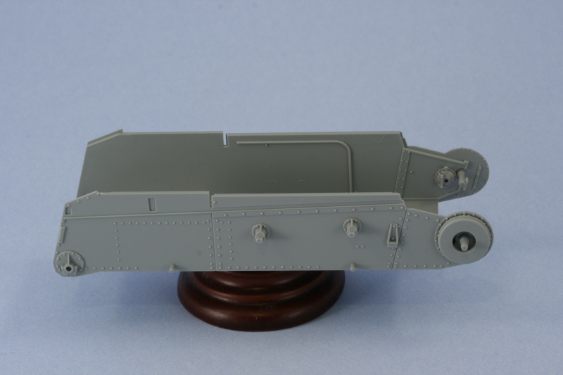
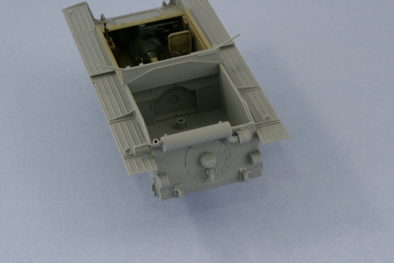
Step 3 deals with the assembly of the rear hull plate details but since the plate itself doesn’t get installed to the hull until Step 5, I decided to rearrange things a bit and installed the plate first, then added the details. This proved to be a wise approach especially in regards to the muffler mounts as they have a very small surface area to mount to and it’s best done on a stable platform.
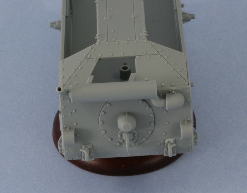
The muffler assembly requires a modification to the exhaust pipe to allow it to be positioned at the correct angle instead of vertical and the instructions point out that the pipe needs the tab cut away to do this, easily done with sprue cutters and cleaned up with a #11 knife. The instructions include a helpful diagram to get the pipe aligned at the correct angle and the easiest way to achieve this is to glue the pipe into the muffler then use the diagram like you would any line drawing and rotate it to match the angle. I also enlarged the hole in the pipe with the point of #11 knife as it appeared too small for my liking. The seam from the two part assembly was sanded down and a test fit of the pipe that enters the hull showed the hole in the hull was too small…so I used a round needle file to enlarge it to the right diameter. The armored cover also required some adjustment with the needle file to have sufficient clearance to mount flush to the hull.
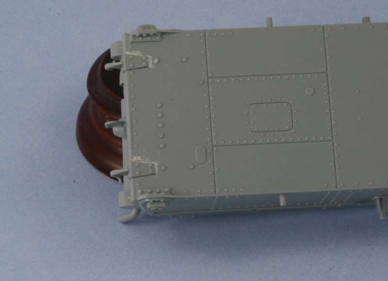
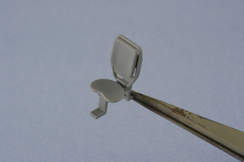
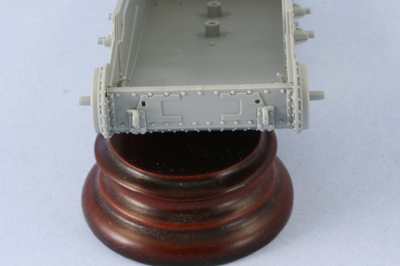
The rest of the details were added, the step gives you the option of armored or unarmored idler covers but only the armored are appropriate. An option is provided for the tow hitch and I chose the one with the rectangular latch vs. the open hook based on reference photos. The armored cover was added to the round transmission hatch and the rear tow hooks installed. Some putty was required to fill gaps on the molded in slots, more on the bottom than on the top. The tow hooks also had to have their tabs trimmed down as they were too large to fit the cutouts provided.
Step 4 deals with the fenders and I skipped that for now but will come back to it shortly. Step 5 calls for the installation of the rear hull plate (already done) and the fenders, so it too was skipped. It’s important to note that this step shows the driver’s knee pad already installed on the right hull side but doesn’t have a part number assigned to it. It’s A17 and I will paint and install that separately. This is an error/oversight on DML’s part in the instructions and is an easy one to miss if you aren’t paying attention.
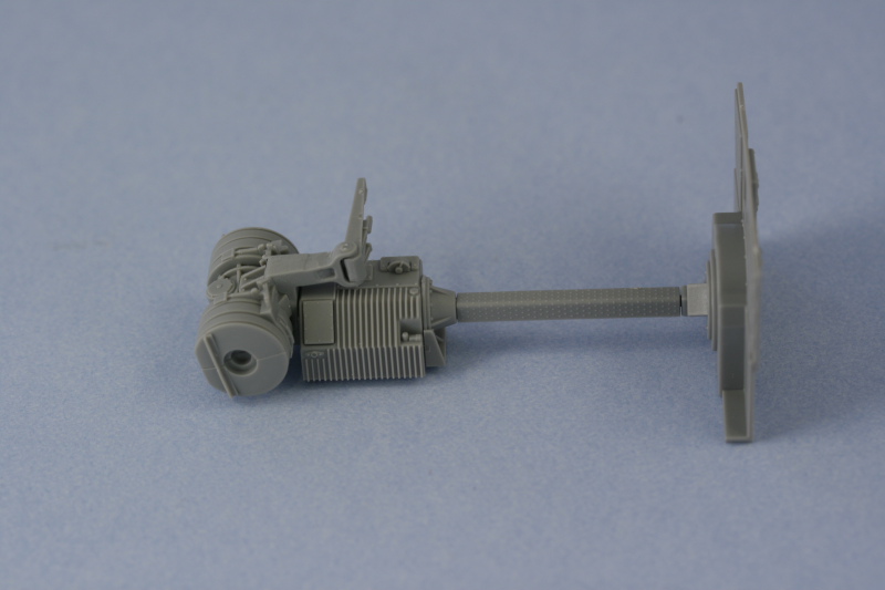
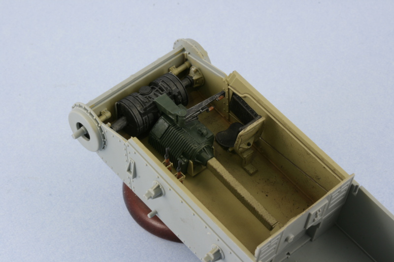
I skipped over Step 6 since that installs the suspension and I’m not ready to do that just yet. Step 7 deals with the interior details beginning with the brake housing and transmission. The brake housing is only visible if you elect to have the glacis hatch open but it’s still a necessary component to get the transmission and drive-shaft placed properly. Because the end mounts were installed in Step 2, it’s imperative that you DO NOT glue parts D46 into the brake housing at this step…if you do, you cannot install the brake housing in place because there isn’t enough clearance to achieve that. Parts D46 have a d-shaped end that must be perfectly aligned with the ends in the hull…so I left them off for now. I opted for the styrene version of the driver’s controls and assembled and attached the transmission and drive shaft. The drive shaft is a little loose on the transmission square peg so I used the rear bulkhead dry-fit to help it set up in the proper position and alignment.
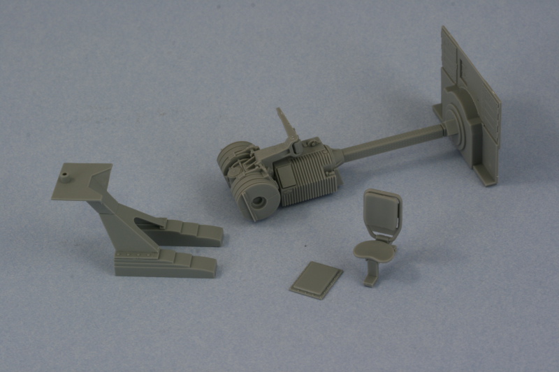
Also included in this step is the driver’s seat. I must say I’m extremely disappointed in this area…the seat mount is 100% wrong…and it’s something DML has known about since this came off the 38t G sprue and yet they’ve perpetuated it into this kit. Probably too expensive to correct the entire sprue mold, but that doesn’t excuse the fact that the mount is pure fantasy. The seat itself is also very inaccurate…it doesn’t have a cushion for the bottom but does provide one for the top. There are no straps for that cushion on the back portion of the rest but they do replicate the ratchet details for the seat adjuster correctly…go figure.
Step 7 also calls for the assembly of the front hull plate. As with the rear hull plate, it’s easier to install the plate first and then add details to it. The mounts for the tow hooks were installed first and, just as with the rear, the hooks needed their tabs trimmed down to fit properly.
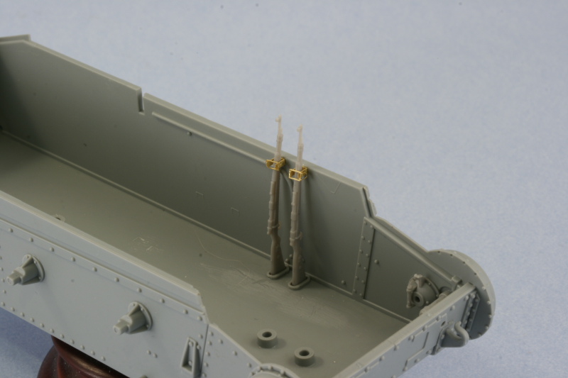
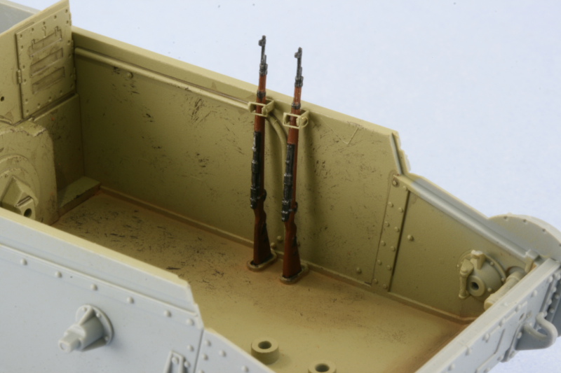
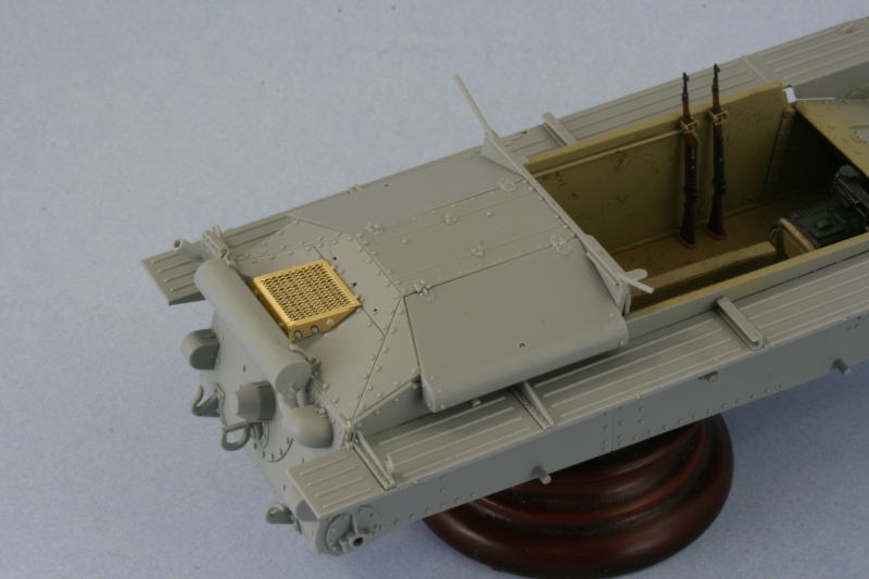
The next little interior detail was the racks for the K98 rifles…there are two and are a combination of styrene and PE parts. The bases are styrene and mold locator lines are provided in the lower hull. The are locator lines for the PE top portions as well…but the kit doesn’t provide any rifles. I scrounged around in my spares bin and located a pair, with some careful gymnastics, the rifles can be taken in and out of the racks so they will be painted separately and then installed. These racks aren’t called out in the instructions until Step 18 and it’s much easier to install them now rather than wait until then when there’s a lot more in the way and a whole lot less room to maneuver the rifles.
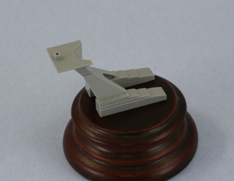
Another interior detail got attention at this point, the pedestal mount for the sIG 33. This is also called out in Step 18 but I went ahead and assembled it now so it could be painted before installation. The choice is provided for either the stacked stair-step style mount or simple I-beam mounts, I opted for the stair-step style. The assembly is a delicate one as the bases are free standing and the only thing holding them together is the pyramid shaped top portion…which is attached to two small base pieces in turn. I made sure to assemble this on a level surface and insured the bases were square as this is an integral piece for mounting the gun.
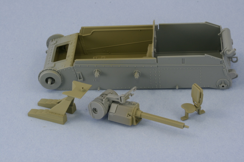
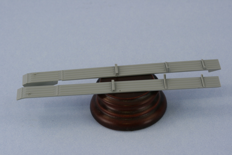
These are all the separate interior pieces assembled today…they will be painted separately from the lower hull and then installed after they’ve been detailed.
Total Session Time: 6 hours
Total Time to Date: 8.5 hours
Moving right along Bill. I wish I could get that much done in six hours.
This kit has got quite a bit of detail right out of the box. I see also those Dragon instructions are living up to their infamous reputations.
Will you be correcting the seats or will you stick to the oob plan?
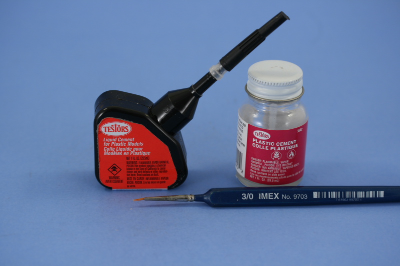
…what brand of glue do you use?
Cool build wbill, those little sIGs are kind of neat.
Hi, Bill, great subject, you should start to call these builds the “38t love story”, there is a life times work on the chassis.
Good luck with the build.
Terry.
Steve, The kit is pretty detailed all on its own but the instructions are suffering from the usual DML inclination to just copy sections from previous kits along with the sprues that they stuff in. The instruction diagrams for the first few steps are clearly cut/paste from the 38tG kit right down to the incorrect options and parts call-outs. As for the seats, I’m sticking to the OOB plan as trying to correct them would require a total rebuild and I’m not certain even if they were replaced with accurate seats what that would do to the layout with the transmission and gun mount. At least there is a seat provided…but beyond that it’s almost pure fantasy on how they designed it.
MR, I use two types of glue primarily…both by Testors. The “black bottle” glue for regular glue and their liquid glue in the glass bottle with a smaller detail brush for application for liquid glue use. I cut down the tip on the black bottle and use a clear tip instead, makes it easier to control the glue. Don’t even bother with the fancy wire-thingy that comes with it.
Seth, thanks for the comments!
Terry, so true…one could spend quite a bit of time just on the 38t family in building all the variants and possibilities. Definitely my favorite group of subjects! [;)]
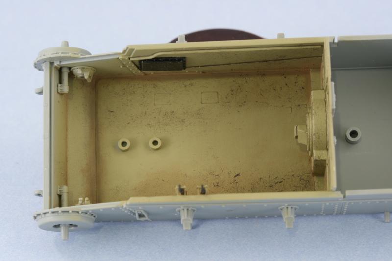
Work continued from yesterday with the interior parts airbrushed with a base coat of 80/20 Dunkelgelb/Light Gray. Rather than mask off the contact points for the glacis and the rear bulkhead, I used the actual parts to perform that task since they are a tight friction fit and no glue or poster blue tack was necessary.
The Kar98 rifles were hand painted with the details done using the magnifier and then carefully installed. The interior was weathered by first stippling Burnt Umber using a round 0 sable brush to create a scuffed/scraped look for the high traffic areas where the crew would stand and serve the gun. The actual vehicle had tread plate on the floor but DML provides only the smooth surface since the hull is a direct copy from the 38tG gun-tank which didn’t have a tread plate floor. After the Burnt Umber had dried, I stippled in some of the base coat color to blend things back in and make it appear more random. Dirt/dust accumulation effects were added using Mig Europe Dust pigment applied dry and scrubbed into the corners and blended into the scuff/scraped areas using both a dry and wet end of a q-tip. A pin wash of Raw Umber was applied to the raised detail, such as it is, to complete the look. The driver’s knee pad was also installed.
The rear bulkhead was removed and reattached to the drive shaft to create one big assembly for the brake housing/transmission/drive shaft and installed into the hull floor. The drive axles, parts D46, were then installed to join the brake housing to the drive ends already installed into the hull in Steps 1/2. This is not the way, in hindsight, I would recommend doing this as getting the axles into position was a wrestling match and much harder than if the ends had been attached to the axle ends and then installed as one unit with the brake housing.
With the interior complete, it was time to go back to Step 4 and get the fenders ready for installation. I added all of the supports as directed except the front ones because of how they interact with the glacis, I wanted to be sure they were positioned properly.
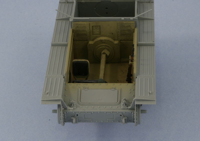
I’m glad I did that as I encountered a slight problem with the right side fender, more on that in just a bit. The fenders were attached to both sides and I didn’t try to introduce any sort of “kink” for fear this would interfere with the attachment of the fighting compartment extensions in later steps. The fenders were glued directly to the hull using the provided molded-on guide using regular glue followed by liquid glue. Once the fenders had set up, I added the front supports and installed the glacis. Once again DML’s tendency to copy parts from a previous kit without modification reared its head. The original 38tG glacis plate had a small step on the right side that’s not present on the Grille H glacis plate…but the fender support for that side still has the notch to accommodate that step. The result is a noticeable gap which required some careful putty work to fill and correct. The glacis was glued into position and the 3 small parts added as the basis for the gun travel lock. The brake inspection hatch was installed in the closed position
Steps 8, 10, and 11 all deal with the engine and since I have no desire to display the engine hatches open on this build, these steps were skipped. Step 9 calls for the installation of the glacis and inspection hatch which I’ve already completed. The support for the rear fighting compartment which overhangs the engine bay bulkhead was added and the rear Notek light installed along with the reflectors that I forgot to install in Step 4. This step also calls for the installation of a round brake light on the right side but reference photos don’t show this fitted to the Grille H, so I left it off.
Finishing up the day’s activities was the installation of the engine deck and access hatches. Three small holes need to be opened up B12 just above the air intake, which I accomplished using a #74 drill bit and pin vise. The PE screen was added as well and it should be noted that later on in Step 20 this screen vanishes and is instead replaced by another PE part, MA34, which I have no idea why it’s there…the part is indeed a screen but it’s far too small to cover the provided area…I gave it a try just to see since I was curious as to why there were 2 different screens included on the PE fret. MA20 is the correct screen from what I can tell based on my references and it includes the option to have the sliding metal insert…the few shots I have of the rear of Grille H’s don’t show this insert as present, so I left it off. The PE screen was attached and the bolts K18 and K19 added by slicing them off the sprue and carefully gluing in position with liquid glue. The three small bolts on the top right hinge for the access hatch were removed per the instructions to allow the perforated shell prep tray to be installed in a later step. The hatches were assembled and added to the engine deck and the entire deck then installed into the hull to complete the step.
Total Session Time: 6.25 hours
Total Time to Date: 14.75 hours
In yesterday’s update, I mentioned about the too-small grill that is called for in Step 20, MA34. The primary references that I’m using for this build are MBI’s “Marder III & Grille” as well as Panzer Tracts No. 18 but I also flipped through Spielberger’s Panzers 35t & 38t and Variants and found the following top-down shot of a Grille H. This is posted for discussion only and to correct my earlier commentary about part MA34.
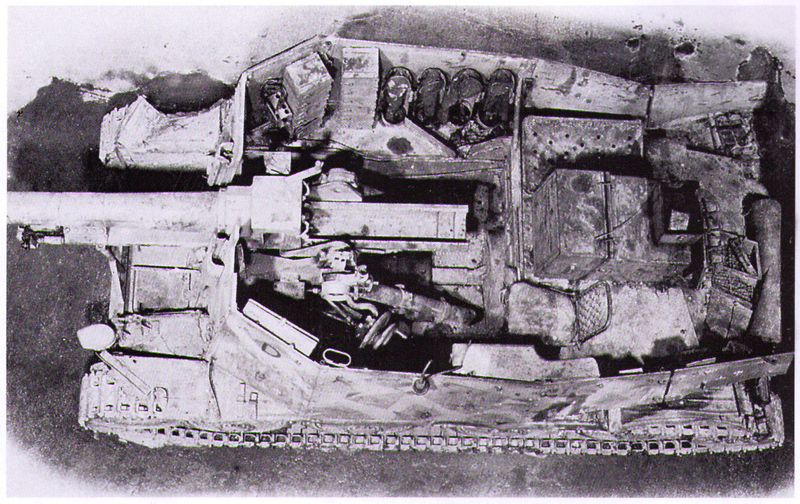
This photo does indeed show some sort of addition on top of the engine intake screen that is smaller than the intake itself but it looks like a sort of field-rigged tray judging by the fact that there’s an object inside it. The DML part for this has it as a screen covered raised extension though, so not sure exactly what they were trying to replicate in the end. The scheme on this vehicle is the splinter-type camo and is included in the DML finishing guide so if you wanted to replicate that vehicle it would be accurate, sort of, to mount it. This view also shows this particular vehicle had the sliding tray adjuster for the regular screen…which intrigued me further. Pics of the initial production vehicle in MBI don’t show this slide present but here it is on an actual vehicle, so again it is an acceptable option if you want to go that route.
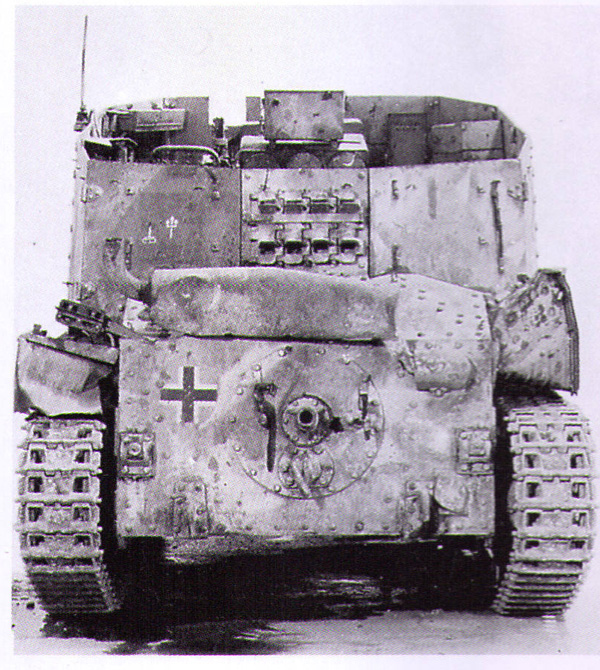
The above pic shows the same vehicle from the rear and also highlights another difference…this one doesn’t have the armored covers for the idler mounts or the transmission access. This may indicate that this is a rebuilt earlier 38t converted over to a Grille (after 1942 38t gun-tanks returned for repairs were often converted to either Grilles or Marders as the case required to fill orders) since it also has a vertical exhaust pipe instead of one positioned at an angle but it’s hard to say 100% either way. At the very least it certainly provides more room for variety!
The detail is top notch, Bill, I particularly like the rifles. The painted appearance is very lifelike.
Thanks Bill! I have a Czech Mauser on the wall in my office as the ultimate reference! [;)] Still in good firing condition although I haven’t shot it in several years.
Great looking progress Bill. Without going and pulling out my 38 M… is the chassis the same for both kits? Curious so I know to watch out for the problems as you point themout.
Interesting and rare shot of an open-topped AFV from above…judging from the markings it belonged to the 2nd PD’s self-propeled artillery battallion in Normandy…you don’t happen to have a pic like that of a sdkfz 250/8 do you?
Marc, thanks for the comments! The M chassis on the 38t family is not the same…it still used most of the 38t components but relocated the engine from the rear to the middle of the vehicle. Aside from the suspension and the engine/drive-train, everything else is essentially different.
MR, unfortunately those shots are in isolation from Spielberger…he doesn’t even ID the unit. The DML instructions finishing guide claims it’s from 2.Pz.Div., Normandy 1944 but beyond that I can’t help you much I’m afraid. Pics of the 250/8 are rare indeed…I’ll keep my eye out for you though. [;)]
Those are the same interior parts, I believe, from the weird prototype 38t-based CyberHobby kit of the Sturmkanone…I think?

Looks good so far, Bill! But I’m curios about that DY interior–was that the norm? I would’ve thought it would have been elfenbaun? Or white?
Looks very good Bill!!
[:)]
Cool, sorry if you thought I was “GRILLing” you about that…
Stick Man, thanks!
MR next you’ll be encouraging people to try the veal! [(-D]
Karl, DML has religiously reused the sprues from the initial 38tG kit so essentially all of their 38t based kits use the same engine, the same interior, etc. to get the most out of the sprues. The DY interior was the norm for open topped vehicles with elfenbein used only for inclosed areas. The Grille H interior is fully exposed due to the way the gun mounts directly to the “floor” due to size and weight…and the driver’s position isn’t enclosed, so no need for elfenbein. The front plate for the superstructure mates directly to the glacis and the entire interior is exposed from the transmission back to the firewall bulkhead.
I just didn’t want you to think I was getting all up in your “grill” about it…