Atlas ICBM, something different, FINISHED

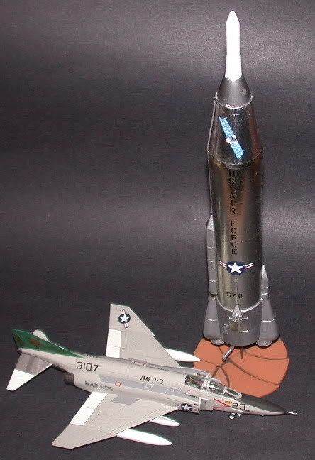
I worked on the Atlas F ICBM at Dyess AFB, Texas, in 1964-65 as my first assignment in the USAF. I recently came across a 1/72 Anigrand resin kit of the Atlas that can be done as an A, B, C or D model. I wanted to modifiy it into an F model, but found this to be totally non feasible. It would be about like trying to modify an F/A-18 Legacy Hornet into an E or F Super Hornet.

I have found several major errors in this kit that will have to be corrected at the beginning.

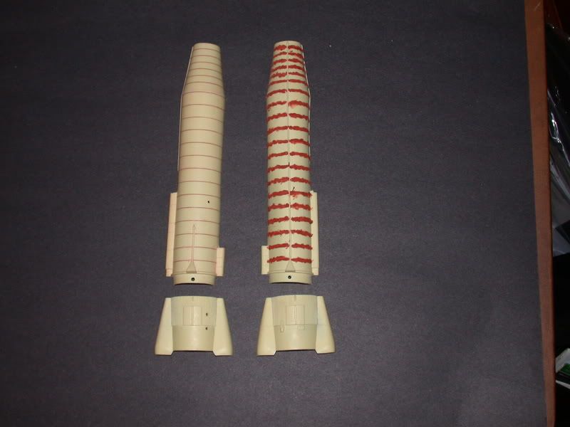
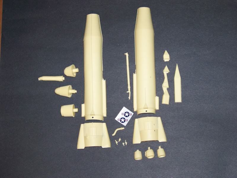
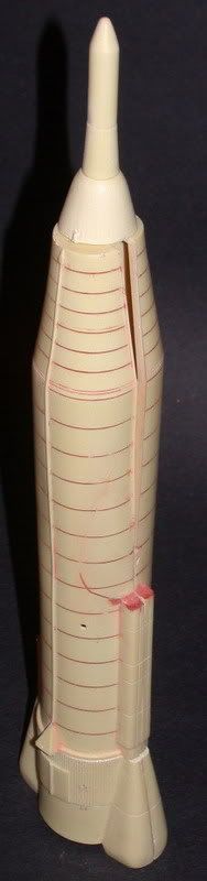
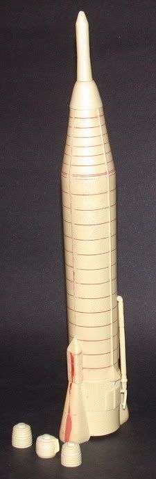
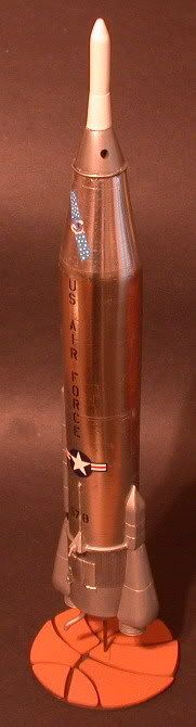
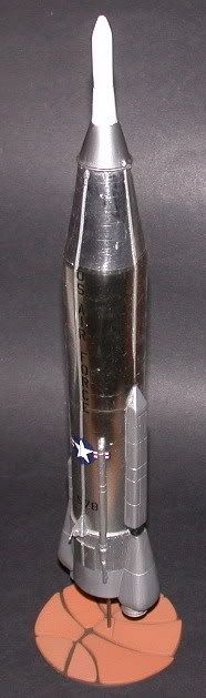
  1. The full scale Atlas had the LOX & RP-1 tank section made out of stainless steel that was only a few thousandths of an inch thick. Essentially just a big metal balloon. The model has panel lines around the circumference of the tank that would scale out to about an inch deep. The first picture shows them with one side filled and the other side already sanded down. The sanded down half is the belly of the missile and the unsanded half is the top.
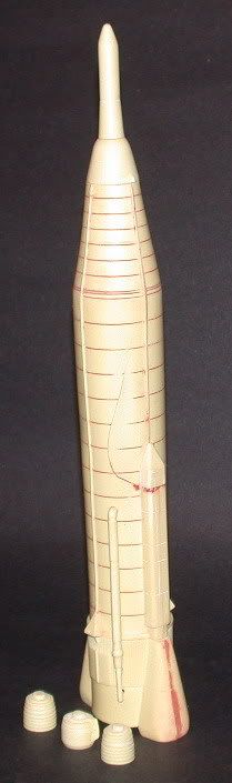
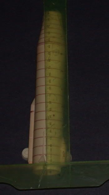
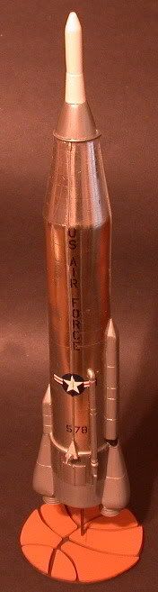
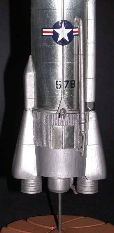
  2. The long pipe in the 2nd picture is the LOX transfer line from the LOX tank in the upper part of the missile down to the engines. The instructions show this installed on the belly side when it should be on the top side.
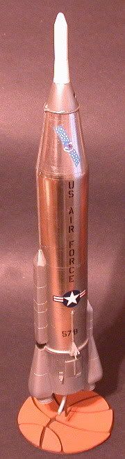
  3. All three nose cone options have huge, vertical, sawtooth striations all the way around. This is correct for the early versions with a test payload. The RV adapter for the ICBM had a smooth finish.

,

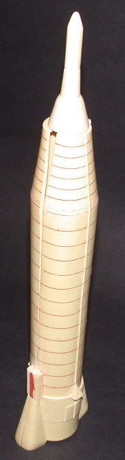
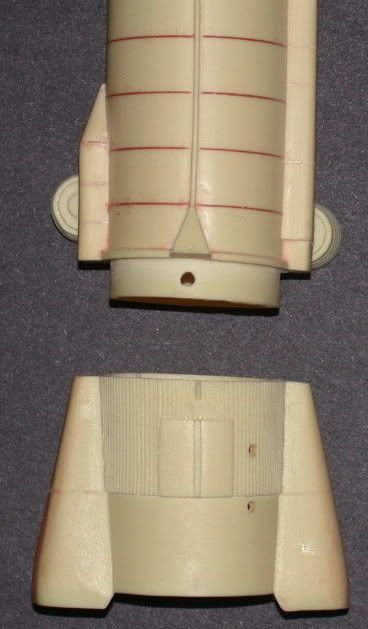
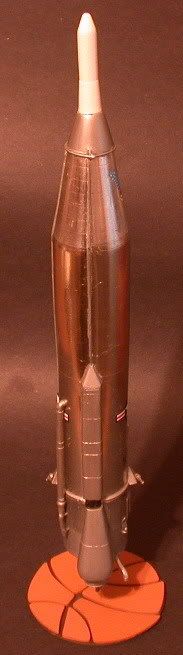
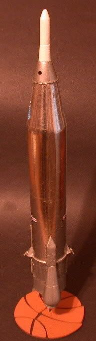
I got the panel lines filled in and sanded, then when I was trying to line up the two tank halves, I busted a big chunk out of one half. You can see the irregular line in the first picture where I patched in back together. Both pictures show the horrible fit of the two halves. I have them glued together at the bottom and just sitting in the skirt section which is also glued together. I had to place a scab patch inside the tank halves and will slowly glue them together from the bottom towards the top. The fairings on the skirt over the booster engines have a horrible gap and the RV adapter doesn’t fit very well either and both areas will need some work. This is my first all resin kit and I am certainly NOT impressed with it.

;

Darwin, O.F. [alien]

I probably should have posted this over in rocket & space section, but it seems the traffic level over there is about the same as the number of pedestrians walking across Death Valley.

Darwin-

Looks like you have your hands full on this one! The fit looks terrible in the photos! Hopefully, you will be able to tame that beast. [tup]

I wonder if you could also post this in the armor forum as it is a type of artillery you might say.

Uuhh, 9,000 miles is what you call REALLY LONG RANGE artillery. I will post it over there.

Darwin, O.F. [alien]

Pretty cool subject, Darwin. Sorry to see it’s giving you such fits.

The first two photos show the overall missile after I managed to get the tank halves mated together. I had to heat the resin in pretty warm water and then super glue them together while holding quite a bit of pressure until the glue set. The RV adapter still needs some work to get it to fit correctly. I added the tapered fairings to both equipment pods on the sides and filled in the canyon, (gap), on the engine fairings. The three little gizmos in front are the exhaust bells for the engines. The big pipe on the side has two functions. The bottom end fits into a connection in the silo and is the LOX fill & drain valve to get liquid oxygen into or out of the upper tank. It also serves as a means to get LOX from the tank to the engines during launch.

,

These two photos show the gross mis-alignment of the joint between the tank section and the booster skirt. The green T-square is parallel to the bottom of the tank section and you can see how much it angles off to the side. It wasn’t feasible to square up the bottom of the tank section, so I had to sand the skirt section to match the angle. You can see that in the second photo.

.

Darwin, O.F. [alien]

You don’t see one of those every day on the boards, and judging by the fit I can see why.

Great to see something totally different, and you look like you’ve mastered that bad boy!

Karl

What I don’t get, how you can remember the details that you do! I can’t remember what I did for lunch yesterday!

I must say, Darwin, you certainly qualify for the title of “Master Modeler”! I have had similar experiences with short run kits that often ended up being introduced to the wall paper at near Mach 1! [:(!] I often wondered what Anigrand quality was like, now I know! [V] At any rate, you are certainly whipping the beast into submission, my hat is off to you!

Brian [C):-)]

Very compelling project!

Super-Neat-O! I’d sure like to see it finished…

I finally got this thing beat into some semblence of a decent model. As noted in the earlier posts, I had a LOT of trouble just getting the basic pieces lined up and glued together. Changes to the kit include:

  1. Move the LOX fill & drain pipe from the belly to the top

  2. Add the LOX overflow vent to the RV collar

  3. Add the reinforcing ring around the base of the RV collar

  4. Reshape the RV collar & remove the ribs

  5. Reshape the vernier engine nozzles

  6. Correct, or at least try, the grossly misaligned mating ring between the tank section and the skirt section.

  7. Smooth out extremely rough surfaces and remove assorted small blobs of resin.

  8. Cobble together all of the decal markings from the spares box. The only thing in the kit was two very undersized national markings

The Re-entry Vehicle or Warhead contained the 1.4 MegaTon nuclear weapon inside a metal shell and was covered with a white ablative coating. (similar to the white coating on the X-15 for a few flights). The RV adaptor collar was made of aluminum and had the LOX overflow vent coming out the side. Photos of a fully fueled Atlas show a large plume of what looks like smoke coming out this vent.
The main body or tank section was made of stainless steel and appeared as a polished surface. The pointed equipment pods on the sides and the covers over the engines were made of very heavy fiberglass and painted aluminum color. The main portion of the skirt was aluminum and the engine bells were a metal alloy that looked like magnesium. The large, bent tube coming out the bottom of the skirt was the RP-1 (fuel) fill and drain valve. Comments welcome, pro or con.

Darwin, O.F. [alien]

, , , ,

More photos of the Atlas ICBM.

, , ,

Well done Darwin! Judging from the fit issues you were dealing with, I figured it would be a while until we saw this one finished. Nicely done, doubt if we’ll ever see another of those 'round these parts. [tup]

Looks great, I build rockets as well. The extra work you did shows, it really payed off. between ther mods and the fit issues you manged to make a winner out of her. If I remember correctly that a single warhead like the minutemen I and II vs the minuteman III which could thorw three MIRV at hardended targets.

Now that certainly is different! You did an excellent job, especially considering the difficulties that you had with the parts fit.

Grandma L

Great work Darwin. With those fit issues, your metal finish is outstanding. Very cool subject, I hope people build more!

Wow Darwin, i dont know how i missed this 1st time round. I love wierd, strange and odd. This ticks all the boxes. It looks like it was a Pig as well. Looking at the finished pictures youd never guess you had any issues with it. Top marks fella. I love it.

…Guy

The Atlas D, E & F, the Titan I and II as well as the Minuteman I all had a single warhead. I am not sure, but I think that the Minuteman II had 3 MIRV’s and the Minuteman III had even more. The Peacekeeper that replaced about half of the Minuteman missiles had up to 10 MIRV’s. The Atlas F that I worked on in '64-'65 had the ability to store two separate targets in the guidance system, but the launch crew had to select either A or B before launch.

It is really amusing to me to think about the computer that was an integral part of the guidance system on the Atlas. It was a big cube, about 3 feet on each side that weighed a couple hundred pounds and all it could do was add, subtract and multiply. There were 3 accelerometers in the gyro platform that fed information for each of the 3 axis (pitch, roll & yaw), to the computer and it figured out where the missile was at that moment and where the warhead would impact if cut loose right then. When the results of those calculations got to a certain point, the BECO signal was sent for Booster Engine Cut Off and the skirt with the two booster engines was separated from the rest of the missile. A little further into the flight, the SECO signal for Sustainer Engine Cut Off was sent and then when the computer figured the RV would impact close to the target coordinates, VECO or Vernier Engine Cut Off was sent, the arming signal was sent to the RV and it separated from the missile and went it’s merry way. If any of those events did not occur within a certain time frame after launch, the arming signal was blocked and you wound up with a very expensive rock.

An Atlas moments after launch.

An Atlas F without RV, sticking it’s nose out of the silo.

An Atlas F at an operational silo. It looks ready to launch, but it is probably just a PLX or Propellant Loading Exercise with a dummy RV.

Darwin, O.F. [alien]

Excellent! Well done!

Your comments and notes are interesting too.

Outstanding job here!

You’ve captured the vehicle nicely, and have done an excellent job with the parts you have before you.

My dad was the technical illustrator for Aerojet General (Sacramento Division, both liquid and solid propulsion sectons) where these engines were built from 1960 thru 1993, and I can tell you that this model would serve well in their display. Be proud of your work and give yourself a big slap on the back!

I received a PM asking me where the silo in photo #3 is located. It is from the 577th Strategic Missile Squadron, site #11 at Willow, Oklahoma, northwest of Altus. While I was trying to figure out that answer I was jotting down some other miscellaneous BS about ICBM’s and came up with the following.

All of the Atlas D, E and F silos still remain, although most have been gutted for scrap metal. The 72 Atlas F vertical silos were mostly gutted and then mother nature filled them with water. I think that all of them are now in private hands and a few have been cleaned up at least enough to enter them without killing yourself. The Launch Control Centers on several have been turned into extremely neat underground homes.
The 2 Atlas D bases with 3 sites each were at Offutt AFB, Omaha, Nebraska, and FE Warren AFB, Cheyenne, Wyoming. Each site had 3 missiles in individual above ground, horizontal coffins.

The 3 Atlas E bases with 9 sites each were at FE Warren AFB, Wyoming; Fairchild AFB, Spokane, Washington; and Forbes AFB, Topeka, Kansas. Each site had one missile in individual ground level, horizontal coffins

The 6 Atlas F bases with 12 sites each were at Plattsburgh AFB, Plattsburgh, New York; Lincoln AFB, Lincoln, Nebraska; Schilling AFB, Salina, Kansas; Altus AFB, Altus, Oklahoma; Dyess AFB, Abilene, Texas; and Walker AFB, Roswell, New Mexico. Each site had one missile in individual below ground, vertical silos.
4 Atlas F sites were destroyed by accidental explosions during PLX’s, one at Altus and 3 at Walker.

Vandenburg AFB, California has examples of all of the various ICBM’s.

53 of the 54 Titan II sites at Little Rock, Arkansas; Wichita, Kansas and Tucson, Arizona were deliberately destroyed with large amounts of explosives to keep the Russians happy. One south of Tucson has been kept intact for a museum.

Titan I squadrons were at Ellsworth AFB, Rapid City, South Dakota; Lowery AFB, Denver, Colorado; Beale AFB, Marysville, California; and Larson AFB, Moses Lake, Washington, and have all been pretty well stripped out. Ellsworth, Beale & Larson each had three sites with 3 missiles each stored in vertical, underground silos. Lowery had six sites with 3 missiles each.

For some reason, the Titan I sites seem to have developed more contamination and are LETHAL to anyone entering them without full self contained breathing apparatus. It is a phenomenon similar to what happened to the ships sunk at Pearl Harbor. The water combines with trash and debris and forms cyanide gas.

Da _ _, once I get started, the BS just keeps rolling along!

Darwin, O.F. [alien]