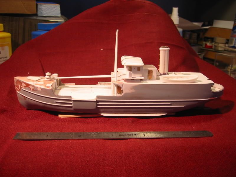
This is my master for a future resin model of a 133 foot US Coast Guard buoy tender. I found a set of lines and plans for it at the Library of Congress’ Historic American Engineering Record (HAER) site.
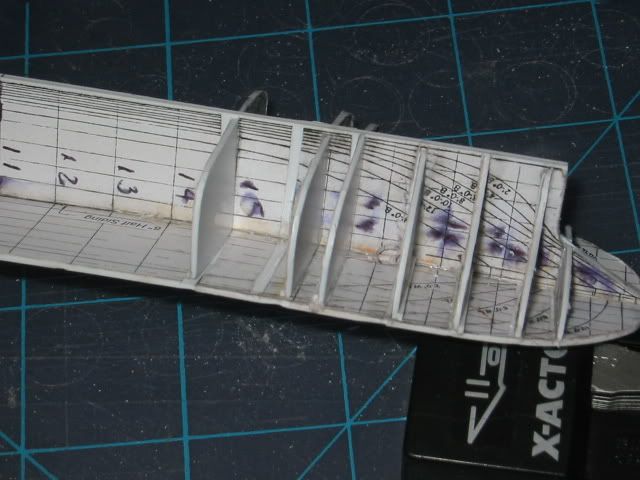
I copied the lines to the desired scale and glued them to some sheet styrene.
Then cut them out and began assembling the ribs and backbone of the ship.
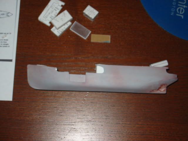
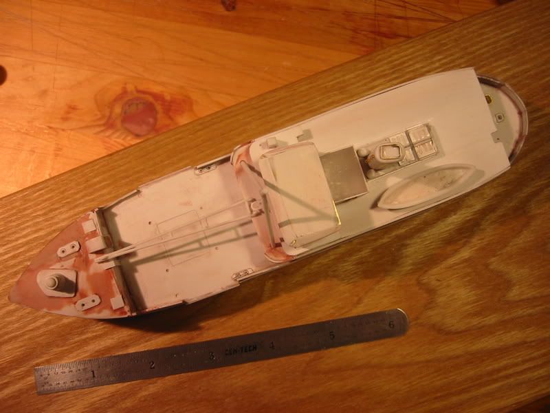
Once that was compelete I sheathed it with styrene and filled that with Bondo. Then sanded & filled (repeat until satisfied). Rubrails, scuppers, and other details are applied The superstructure is plexiglas blocks sanded to shape or built-up styrene structures
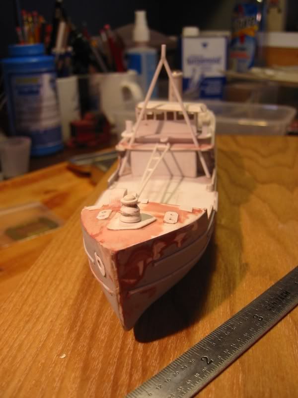
A bow-on view to give an appreciation of the A-frame crane (I’m still working out the kinks in the rotating assembly).
The parts are just stacked together, I know that the stack is on crooked. I have some N-scale railroad detail parts to be placed, bell, air horn, acetylene tanks. Ialso have to go back to the profile plan and locate the portholes along the deckhouse. I have some PE ports which need to be added.
Inspiring! I wish there were more USCG subjects available. Everytime I drive past the base in Seattle I think what a great model those icebreakers would make.
Ed, I have a question about the plans you started with. I have thought I someday might try what you have done here with a C4-S-A1 troopship hull. That would lead to all kinds of scratchbuilding oportunities, from the original troopship to the various civilian modifications those versatile ships provided. (Revell’s old hospital ship seems to be the only injection molded kit based on that hull, and the scale is too small for me.)
Anyway, I have the catalogue from the Smithsonian, “Maritime Administration Ship Design Collection”. Under the C4-S-A1 they list “Forward Body Lines”, “After Body Lines”, and “Body Plan, Frames”. I see your plan just says “Body Plan”. So, my question is, do I need all three of those or just the one titled “Body Plan, Frames”? The other two are $30 each, so I hate to buy them if I don’t need them.
Wow, just looking at that 133 foot shuddering S&%#house brings back so many wonderful memories of leaving Rockland Maine at O dark thirty for a 10 hour run up to Frenchmans Bay or Eastport to tend some buoys(we had 400 plus). You can sign me up for a couple of those models when they go into production, I have off set lines and plans but seem to lack the will(I’m lazy in retirement) to scratchbuild ships these days. Looks like a top notch job, I hope you’ll keep us up to date as to a production run. Why I can almost feel the White Lupine swaying and slamming its flat bottom in 8 foot seas and the bridge crew turning a lovely shade of green…
“Theres nothing like the smell of seaweed and starfish cooking on a hot steel buoy deck in the morning, it’s the smell of productivity”
I don’t know the contents of the Smithsonian for sure, or the exacgt terminaology used
I also used these plans along with the body plan cross section lines.
You really need both to establish the shape of the hull. The Smithsonians Forward Lines may be the cross scetion and elevation for the forward half and Aft Lines may be for the back half. Or they may be just the half the elevation.
The Smithsonian’s Body Plan Frames may be similar to this.
It gives the shape of the hull, and some idea of the space within. You can use it, if there are sufficient of them to set the shape of the hull and can accurately determine their positioning longitudinally on the plan. You can see that it would be difficult to set the shape of the hull with just 4 lines.
I’m sorry I can’t give you a better answer. Perhaps if you post the question on a naval interest board like SteelNavy (steelnavy.com), someone may have the plans and can give a better answer.
I may just take a chance and order the body plan, which is only $10, along with an order I’m putting in for plans from the Z-EC2-S-C5 Liberty Ship Airplane Transport. If I ever get to doing a hull from scratch it will be a long time in the future anyway.