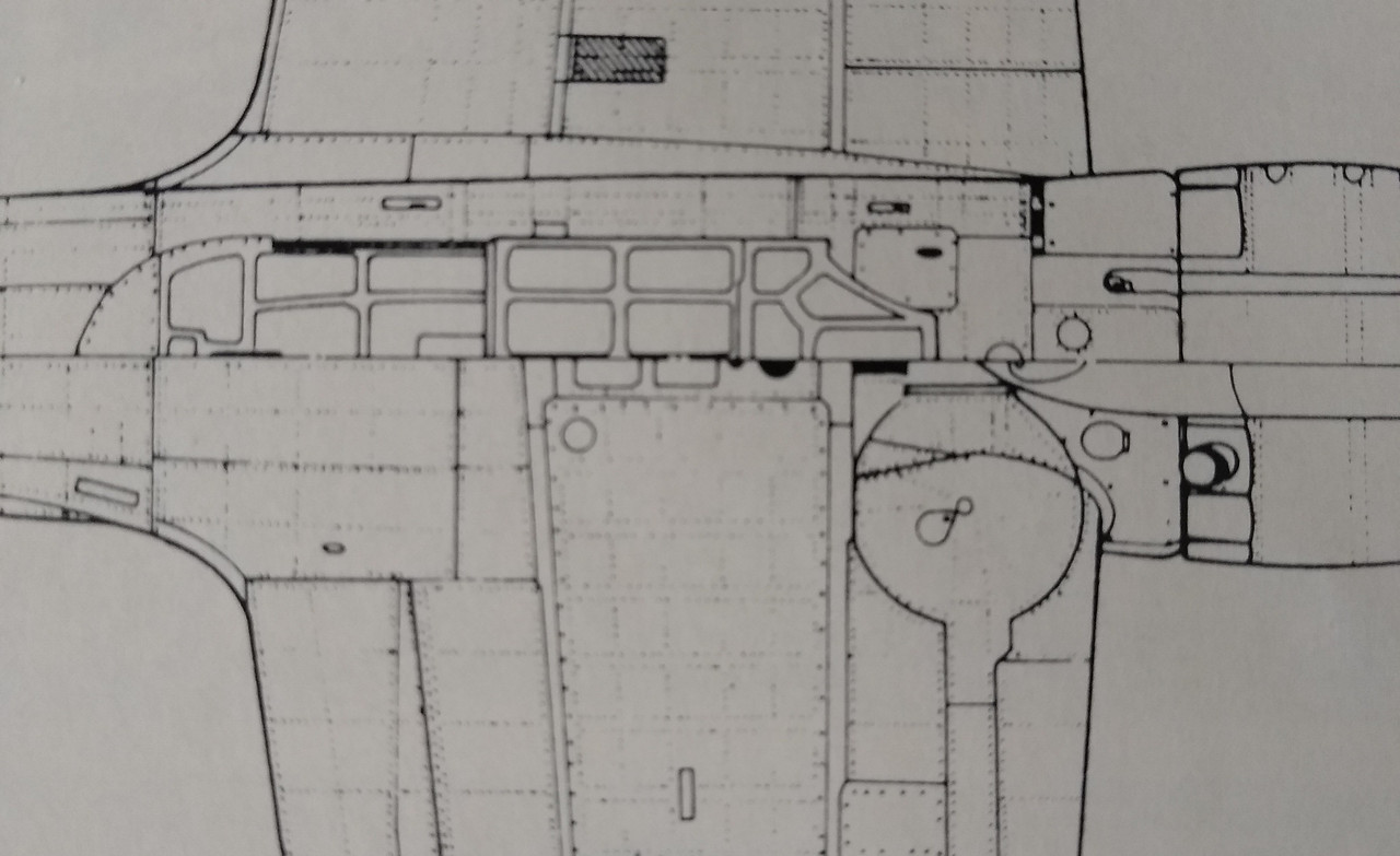
After a Zero ejected its drop tank, what was left under the plane? I have read that there was nothing left protruding. But were there any visible holes left? Some photos show a small rectangular hole immediately in front of the front main spar, and an also small keyhole-shaped hole slightly behind the front main spar, but other photos show only one of those two holes, and still others show a fully-covered surface with no holes at all. The photos that I am referring to are generally from museum Zeros of from current flying aircraft; I couldn’t find any clear enough WW2-era pictures to check. Technical drawings sometimes show these holes and other times they don’t.
I think that it depends upon the variant of Zero. The A6M2 and A6M3 had a connecting fairing that dropped with the tank. The A6M5 had bracing framework instead. I’m not sure if that framework remained on the aircraft, like a bomb rack, when the centerline tank was punched off.
The later in the war and as resources dried up such niceties as fairings on drop tanks or even metal drop tanks were omitted. Don’t know for sure but would guess that the sway braces from the later tanks were attached to the tank not the aircraft so would go with everything else.
Wow, I am impressed at how many responses I have had within 12 hours of my initial posting! Thank you, guys!
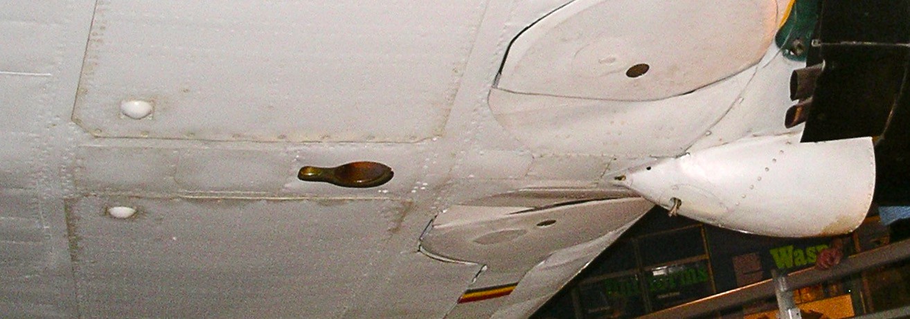
Your picture of the tanks showing the large protrusion + small protrusion really do seem to fit quite well (literally!) with the “keyhole” attachment point. I don’t seem to have picture-posting privileges here, or I’d show you a photo that I took 11 years ago of an A6M5 Model 52 Zero at the National Air and Space Museum, which shows the keyhole-shaped opening, which is rather shallow (maybe 1 cm or less deep in real life?), and inside of it two smaller holes that go deeper and seem to correspond to the large and small protrusions in the tanks. For me, this has solved the question of the “keyhole” attachment point.
It still leaves open the question of the somewhat smaller rectangular opening immediately forward of the forward main spar. Was it an open hole, or was it normally covered?
By the way, I am building the ancient Bandai 1:24 scale A6M5 kit. I am modifying it to be an A6M5a instead of the intended A6M5c. It’s a challenge, because quite a few parts don’t fit well with each other. Also, some areas have required me to make substantial modifications. The cockpit frame was internal, so I sanded out the entire frame, and then returned it to transparent. So far, I am overall happy with the (slow) progress.
I have seen similar technical drawings. It shows the rectangular opening immediately ahead of the main spar, and the large and small circular openings (“keyhole attachment”) a little bit behind the main spar. The “keyhole area” is resolved as far as I am concerned.
The rectangular opening is now the remaining question. Your drawing shows it as open, while my photo from the Museum shows it as closed. The question is, after release of the tank, would this port be open or closed. My guess is that it would be open, but I really don’t know.
(My previous posting, as well as this one were meant for HooYah Deep Sea.)
About the rectangular opening, it is also possible that it was not for any connection to the drop tank, but some sort of access port while the plane was on the ground. If so, it would probably be in a closed position both before and after ejection of the drop tank. So, we are left with that uncertainty: rectangular port closed or open?
Looking at the Tamiya Zero and really trusting their research I would say that the rectanguar hole is the ejection port for the nose guns and has nothing to do with the drop tank. It is just too far forward and sits well to the port side of centerline. There are also no fittings on any of the pictures of drop tanks that would line up there. All he tanks appear to have only the round or keyhole shaped (the tube with the flat bar behind it) sections meeting the airframe.
I just looked at the Tamiya instructions, and indeed they consistently show the rectangular hole as slightly off-center, although it’s to starboard of the centerline rather than to port. You need to keep in mind that you are looking at the plane from below! [;)] But I also have seen other sources that show the rectangular hole perfectly centered (for instance, Osprey’s “Imperial Japanese Navy Aces 1937-45”, by Henry Sakaida).
As to its being the ejection port for the nose guns, I thought that the two roundish/tear-shaped holes immediately outboard of the machine guns (on either side of the “hood”, the “upper cheeks”, so to speak) were the ejection ports. At least, that is suggested by a cutaway graphic of an A6M2 shown in “The Great Book of World War II Airplanes” (agh, I wish I could post images!), but maybe those holes are there for some other purpose, like for the ejection of some gasses from the guns?? Of course, the different versions of the A6M5 had varied armament in the nose (2x7.7 in A6M5 and A6M5a; 1x7.7 + 1x13.2 in A6M5b; 1x13.2 in A6M5c), possibly with more than one routing path for the spent cartridges. Still, at this point my bet is that cartridges were ejected through the “cheek” holes, but I may be wrong.
In regard to the rectangular hole’s being too far forward to have anything to do with the drop tank, I believe that you are absolutely right. The fairing for the drop tank starts aft of the forward main spar, while the rectangular hole is immediately forward of the forward main spar.
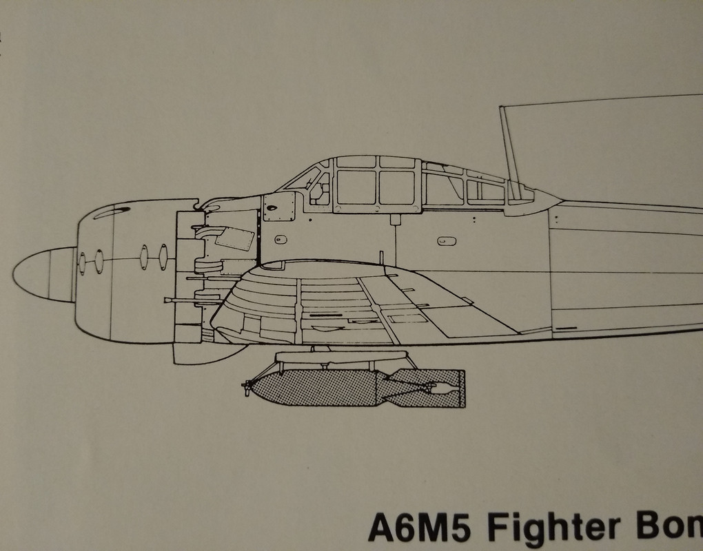
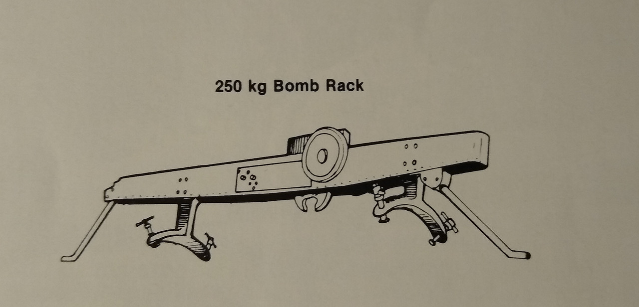
I’m tending to believe that the ‘square’ or ‘rectangular’ opening was open, as I believe that it is the same aperature used for the centerline bomb rack.
I tried to contact three different aviation museums on the subject, but either they didn’t have an A6M or they didn’t answer the phone. Sorry.
Yes, I have seen that photo in internet. The attachment area seems quite different from that of most other Zeros. The “keyhole” is extremely far back, and has a reversed direction: wide part backward; thin part forward.
According to John Foster (http://rwebs.net/avhistory/history/zeke32.htm), “in the center of the front spar is a permanent fitting for an 87-gal. drop tank, a very clean little unit that leaves no projection outside the fuselage once the tank is dropped”, and this is what I went along with. It’s hard to decide!
I’m tending to believe that the ‘square’ or ‘rectangular’ opening was open, as I believe that it is the same aperature used for the centerline bomb rack.
HooYah Deep Sea: I don’t think so. The connector for the centerline bomb rack, according to the side view of the Zero that you show, is clearly back from the forward main spar (the skinny vertical white line on the wing underside), while from all other sources we know that the rectangular opening is immediately forward from the forward main spar.
Thank you for calling the museums. That’s clearly going “above and beyond”!
The opening in question is about 3 scale feet forward of the attachement point shown in your drawing here. The drawing shows it aft of the panel ine and about lined up with the rear of the windscreen.
The opening is well forward of the wing panel line and in front of the windscreen. If placed in the opening the rack and bomb would hit the scoop and block the landing gear doors.
I think the attachment point for the bomb rack is under the hinged panel just aft of the drop tank opening. You can see it below.
OK that opening between the wheel wells is most certainly the spent casing ejection chute exit.
In this drawing you can see the chute (in green under front of windscreen) leading from the gun breech’s down the side of the aircraft outboard and aft of the oil tank and lining up exactly with the opening.
This would be why it would be closed or even faired over on museum aircraft as they have no casings to eject.
(Am practicing how to upload images. Let’s see if I can make my Zero from the National Air and Space Museum show up.) The reddish area is what I have been calling the “keyhole” area. Notice the two deeper circular holes within it, one (at the front) wider than the other.
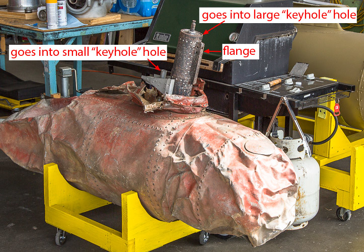
Now that I’ve learned how to upload images, here is my interpretation of the protrusions that go into the “keyhole” area’s two holes. Notice that the large protrusion has a flange; that is NOT what I meant by “keyhole”. The “keyhole” is the reddish area shown in the museum photo The flange would go into a small groove at the front end of the front hole.