#99 DML Sdkfz 234/2 "Puma" COMPLETE Pics P. 4

I have all 4 of DML’s Sdkfz 234 kits in the stash and the /2 is the only one that I don’t have a whole lot of AM stuff to go with it so I decided to make this one a “guinea pig” of sorts and just build it OOB with the only addition being the Griffon barrel that I had picked up a while back on sale to round out an order to qualify for free shipping. Work began in Step 1 by preparing the chassis tub and installing the longitudinal braces and some detail parts.

Step 2 installs the steering gear and mount hubs for the 8 wheels. The kit diagram here is needlessly confusing and busy IMHO since it insists on numbering each individual part with an arrow to go with it even though all of the parts install exactly the same with the exception of the wheel hubs. These hubs, parts D18 and D19, are directional in terms of front and rear and are the ones you have to be the most careful about. In order to insure I didn’t miss any parts in this step, I crossed out each part number as I worked through the installation until all 8 stations had been assembled and in place. The steering arms aren’t positionable without modification and I decided to just leave mine all in the straight alignment for simplicity’s sake. It is worth noting that you need to think through the order of the parts placement as the D18/19 hubs are designed to be trapped between the upper and lower frames and the pin sizes are different to help insure they all get aligned in the right direction.

Step 3 continues work with the suspension by adding the leaf spring bundles and their mount points. The springs have fine mold seams that need to be carefully removed top and bottom but otherwise are beautifully molded. The springs did need a little encouragement to sit properly on their attachment ends and I used some smooth-jawed copper soldering clamps and liquid glue to firmly seat them in position.

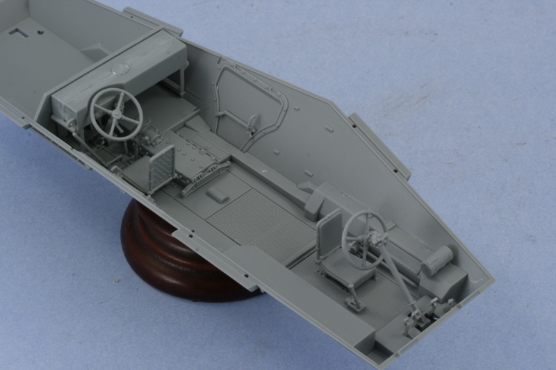
Step 4 is a sub-assembly step that prepares several items for installation into the lower hull tub in the interior. The front and rear driver’s seats are assembled along with the foot pedal arrangements and the steering wheels. The pedals are very nicely detailed, with molded on “K” and “B” details for “gas” and “brakes”! The rear bulkhead and fuel tank is also assembled and the bulkhead has 4 mounting holes that have to be opened up with a pin vise to allow the tank to mount properly.

Steps 5 and 6 deal with the installation of various parts into the interior including those assembled in Step 4. I made the mistake of installing the rear bulkhead/fuel tank combo first when I should have done it last. This was a mistake in the sense that it made the installation of all the other detail parts much harder due to the confined space…something I’ll have to remember when I build the others in the future. I had decided not to paint the interior since this one is a closed top but there are some raised ejector marks that would be visible on the finished interior if it were exposed, so those too would have to be dealt with on future builds.

Continuing on in the instructions with Step 8, the lower hull was joined to the chassis and the remaining tie rods and steering gear installed. Based on my experience with the instruction order, I have to say that I think it’s better to add the tub to the chassis before adding the interior details as I needed to use a couple of rubber bands to get an even join front to back and the presence of the interior details made this harder than it would’ve been otherwise. I also completed the installation of the spring parts from Step 9 at this point, another tricky assembly due to the fact that the slots molded in the hull side for the D2 parts weren’t a good fit. This meant that the parts had to be trimmed and/or sanded down slightly to fit properly.

Step 10 added the little wing-like protections for the front and rear suspensions and also calls for the installation of the inner wheel hubs. I’m not exactly sure why that’s called for at this point since the actual wheel installation doesn’t take place until the very end in Step 25. I cleaned up the hubs and dry-fit them just to see how the vehicle would sit. So far all the points make contact so that’s a good thing. The hubs were set off to the side and will be added to the wheels later on.

The instructions contain another oddity in Step 11 in that this step includes details and options for the armored visors depending on whether they are in the open or closed position but doesn’t actually assemble anything. That’s because the parts you need to complete the visors, the external armored covers, aren’t called out as parts numbers until Steps 12 and 13! Both of those steps add details to the interior of the upper hull half and I installed the front set of visors for the driver in the workable mode so they could be posed open later on. The rear set I installed in the closed position. The other interior details were also added just to see how it would all look as a practice run for future 234-based builds but none of it will be visible on the finished build unless the turret is removed. I also opted for the open vents for the engine deck and those were installed as well to round things out.

Step 15 is a very important step as it joins the upper and lower hull together and also adds the side bins and fenders. Test fit of the hull halves was generally good with just some slight gaps at the rear due to the angle of the rear bulkhead in the interior. I trimmed this down a bit with a shark knife and that resolved most of the problem with some strategic rubber bands taking care of the rest. The rear hull plate was also added to insure proper alignment with the top and bottom.

Once the glue had set, the rubber bands came off and the side fenders were added. I wasn’t paying close enough attention and didn’t realize that I had neglected to add the inner portions that represent the stowage boxes. The instruction diagram shows these as already installed to the hull side with number call outs and I completely missed that before adding the side fenders. Of course, the glue had already started to set so I had to carefully remove the fenders from both sides, install the boxes, then re-attach the fenders. This resulted in some slight glue damage to the hull sides that required some careful putty work and sanding to correct and restore everything back to the way it should’ve been if I’d been paying a little more attention. Something to remember for next time for sure!

Next up will be tackling all the various gear that goes on the fenders, some of which will be installed right away and others left off until after painting.

Wow Bill, you’re chugging away at full steam. Didn’t you just finish #98? That’s a lot of progress for one build log post too. That thing will be done in no time at this rate especially since it’s OOB. I’ve always wanted a puma so I’ll be watching this closely for sure.

Erik

NO KIDDING! I bought this kit from LHS with 50% off for only $23 last week. I will definitely keep my eyes glued to your build… good luck!

Plastic Eyes Glued On Cacti

What your not done with #99 yet? [:-^]

Really though she is looking Excellent so far.

Was wondering, where can one buy those claps you mentioned in step 3?

See Ya

Scott

Bill I did the same thing, probably for the same reason, when I built my -3 but I did not pull the fenders off. That may have been easier than trying to get them to fit up and under.

I got the /1 in my stash. My favorite of the four (/2 is last!) Will follow with interest!! [:)]

Damn, you’ve gotten more done on this, and in far less time, than I have on my /4 conversion.[sigh]

Good luck on this one Bill, I have it myself and always put off on starting the kit. I would like to have the interior myself but I’m a bit skeptical about the accuracy of the interior, especially the turret, all the main bits seem to be there but when I look at the instructions I can’t help thinking that something is missing. Probably just me.

I have studied the kit long and hard and always think about how the kit differs from the old Italeri kit. I built the Italeri kit many moons ago and for along time it really was a star kit. I loved it. I actually built all the Italeri offerings, but I did correct the 234/4’s PAK mount.

Well this might be the catalyst that starts me back to this chassis, just have to wait and see how you progress.

Terry.

Ok, I have a small confession to make. I actually started work on this one a week or so ago while the RSO was drying and my wife had a PTO night and I was stuck home alone with nothing good on TV! All of the progress that you see didn’t happen in the short days since #98 was completed. [;)] Thanks for the interest…and it’s also worth noting that I put “Puma” in quotation marks since this vehicle never actually received that designation officially and is a post-war modeller’s convention…but since people search for that, I decided to include it just to be safe. [:D]

Andy, you definitely got it for a good price! It’s a very detailed kit, especially on the undercarriage, even though much of it won’t be seen without special accomodations on this particular variant. Glad to have you along for the ride.

Scott, I bought mine from MicroMark. http://www.micromark.com/ Originally had bought them for soldering purposes but they work equally well for small clamping duties as well. HTH!

Marc, I tried to fit them after the fact and just couldn’t make it work…but now I’m wiser for it when I get around to the other 3 in the series. [(-D]

Lasse, the 234/3 is my favorite in the series…not sure why but it’s got that mean snub-nosed look/feel to it with that short 7.5cm I guess!

Dre, what are you doing with the /4 conversion out of curiosity?

You sneaked this one in while I was responding to the others terry! I don’t know how accurate the lower hull is but I share your sentiments about the turret…very sparse with essentially just the gun breech and the hatch detail for the commander and gunner. No other equipment at all. Of course that may be just due to the fact that the turret is tiny to begin with but there isn’t any kind of ammo storage provision for example and that, at the very least, is something “missing” IMHO. I too built the Italeri 234/2 and it’s totally blown out of the water by the DML kit now but was the only game in town for a long time. Hope I can provide some inspiration along the way! [;)]

Wbill76- I’m adding IR scopes, lamps and what-not to the base vehicle. There’s my long-neglected WIP thread on it around here somewheres.

Nice job Bill. Looks like a fun build. I still have the old Italeri Puma. Have yet to start it.

AH HA…your cheating [oX)]…I thought you had found modeling heaven where the days are 48 hours long and half the day is for modeling.

Either that or you have elves coming in and helping you while you sleep!

Nice start Bill. Good recovery from the whoops.

As far as the micro clips, I use them all the time. Don’t pay for micro mark and shipping, go to any Radio Shack. You get a bag of 10 for about $2. They are great.

Rounds Complete!!

Nico, thanks for the interest! I built the Italeri kit a while back as well and there really isn’t any comparison now to the DML kit other than the Italeri still looks like a 234/2. [:D]

Mike, Cheating? Nah…just multi-tasking! [8-] No elves in the basement either or I’d be well on my way to #200. It’s the darn immigration/labor laws you see…

You jogged my memory on the micro clips…I thought I’d got them from MicroMark but actually bought them at RadioShack…I dug around and found a baggie of spares that still has the RS SKU# on them! Had to hunt around for them at one of the local stores here as not all of them carry them but found them eventually and you’re right about the price. Very cheap. Something that small I’d only order from MicroMark if I had a larger order that already covered the shipping costs for sure. Thanks for the nudge!

Bill- I will be watching this build with great interest! I almost bought the /4 when it was released, but have not yet. I do hope to get one soon and your WIP will help immensely! You have probably already saved me from forgetting to install those stowage box pieces! [:D]

Nice subject for #99 Bill, tough looking little guy.

Julian

Hey Bill,

i love that little vehicle and I know you will do it justice!

Frank, Julian, Edmund, thanks for the vote of confidence and glad to have you along for the ride.

Made some more progress here and there on the various details with this build now that the hull and fenders were all in one piece. The first area in Step 16 deals with the front and installs the bumper, Bosch headlights, and width indicators. I opted for the supplied brass width indicator posts and, while the instructions don’t mention it, there’s a bending guide provided on the back of sprue TF. The guide itself isn’t stiff enough to do the actual bending but using a pair of pliers and checking with the guide insured I got the desired angle. You do have to be careful to install the right guide for the side with the driver’s mirror as it has the little mounting bracket as an added detail. The kit tries to help with this by packaging them separately on the card insert for the multi-media but once you get them out of the package it’s easy to confuse them if not paying attention. The posts were glued in position with small amounts of CA gel and mated perfectly with the provided mount holes.

Step 17 is a simple step that deals with the rear hull and provides the option of fitting the spare tire holder or not. I opted for the holder but left the actual wheel off for now since that will be painted and installed separately.

Step 18 continues the work on the rear with the assembly and installation of the mufflers and rear fender extensions. There is a small error in the instructions in that the exhaust pipes that connect the hull side to the mufflers are labeled backwards, part E42 actually belongs on the right side and E47 on the left, something easily discovered once you try to fit them as directed since the angles don’t line up properly. The right side muffler has the option to have the exhaust pipe pointing either inward or outward and I opted for the outward configuration. Some slight putty work was needed to fill small gaps for the exhaust pipe on both sides. The rear Notek light was added as well and the kit provides two options…one with the flap molded on in the down position and one with a PE flap and the option to pose in either the up or down position. I went with the molded on part since I had no particular reason to show the flap in the up position…it’s a nice detail consideration though and will go into the spares bin for possible use on future projects.

Step 19 begins the work on the fender details with the left side going first. It’s a busy step with a lot of parts and sub-assemblies for the jack and the jerry cans, so you have to be careful not to miss anything along the way. A small molded on projection has to be removed for this variant, something that was easily done with sprue cutters and then carefully sanded down. I added the optional MG ammunition box and also went with the rear 2 jerry can racks instead of the extra stowage box option. I used the kit supplied PE lifting hooks instead of the styrene parts as they were more in-scale and smaller than the styrene parts. That meant that the molded on locator points had to be removed first and sanded down before gluing the hooks in place with small amounts of Gator Grip glue to allow some work time for their proper alignment and positioning. In order to facilitate painting and detailing, I left the jerry cans and the upper portions of their holders off for now along with most of the pioneer tools.

Step 20 continues the effort with the right side fender. I opted here as well for the optional 5.0cm ammunition box but only mounted the PE holders so that the box could be detailed separately before installation. There aren’t any locator marks, just a small diagram indicating that the rearmost holder be 22.5mm in from the bend in the front fender…so I carefully bent the holder to shape and then installed it first, placed the box in that holder and then installed the second bracket so that the two would align properly but still allow the box to slide in and out for later installation.

All of the fender gear was removed from the sprues, cleaned up, and assembled where needed even though it wasn’t going to be installed just yet. The jack came integrated with the top brackets for the holders and all of the tools have molded on clamps/holders as well. I will add the missing clamp handles with Griffon parts later on just before installation. The six jerry cans assembled beautifully with no issues and are a revised design from previous DML kits in regards to the spouts and handles. They don’t have any stamping as to type so can all be done as fuel cans. The 5.0cm ammo box did have a seam on the top that required some careful putty and sanding work to correct. I also slightly modified the shovels by thinning down the rear shovel head edges with a #11 blade to give them a more in-scale thickness.

Next up will be the turret and gun!

Your Puma is really puuuurrrring…cool looking AM muzzle brake…