All I can say is this is freaking amazing . . . and way too cool !!!
Your production looks great. Makes me want to play around with these 3d printers - how do you get your items so smooth? A lot of what I see is a bit unrefined and needs cleanup. Also, I assume given your background that you are VERY comfortable with the CAD type tools. Really fun to watch this build, thanks for posting.
I point out that this book
https://www.amazon.com/Visual-Battleship-Jersey-Iowa-Class-Battleships/dp/098998043X
has plans for all the levels of the turrets and has photographs of all the crawl spaces in the turrets.
I am told that Volume 4 in the series will cover the turrets in detail. Currently Volume 2 is in the works.
In regard dimensions:
The front face width 31’-10"
Vertical lower front 12"
Guns are spaced 10’-2"
Turret Length (Armor) 50’-7 1/2’
Height 10’ back 9’-10" front
Roof Length 44’-2"
Turret Width 239 33/64" from CL to widest point
Width of Roof 220 17/32" from CL to widest point
Width of Roof at rear 15’ 4 51/64" from CL
Radius of Rear: 32"
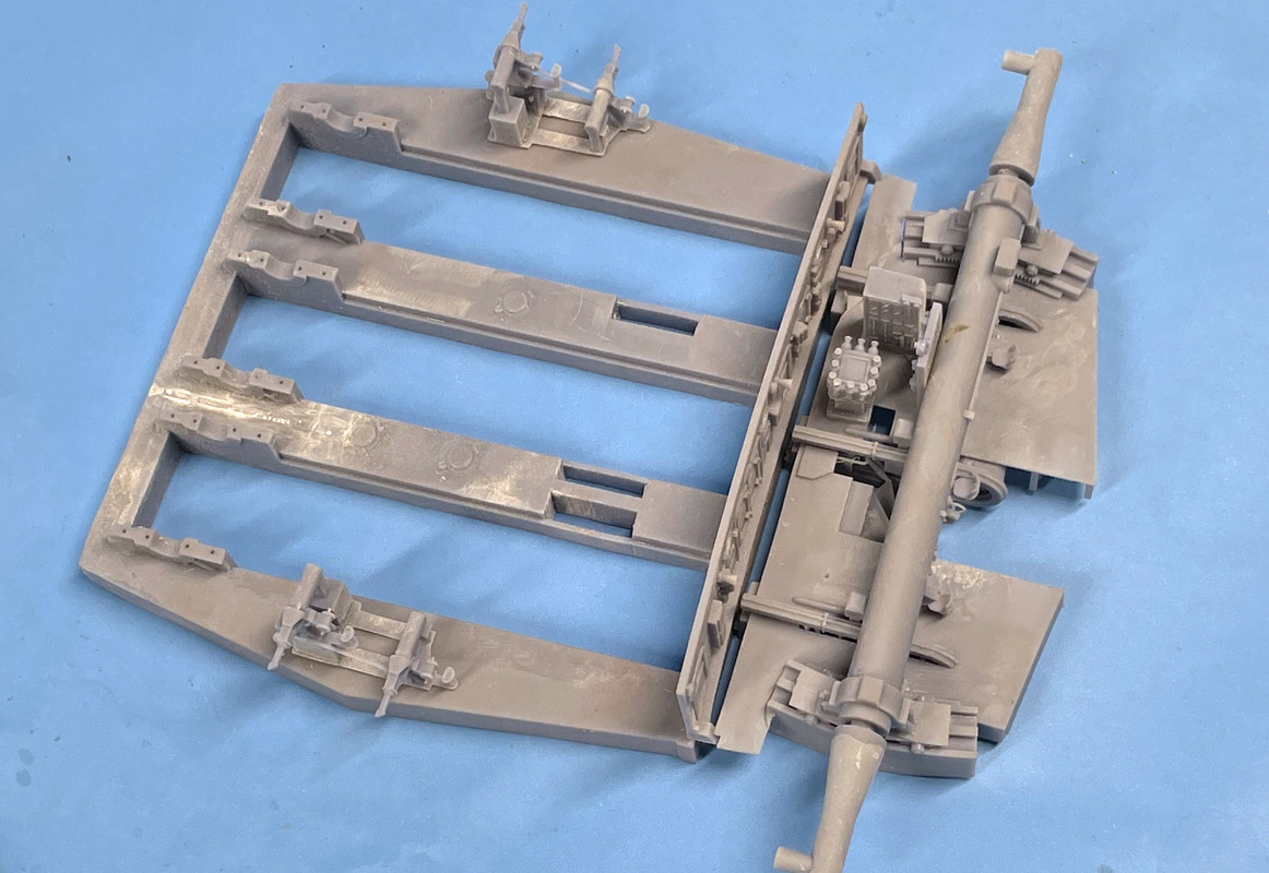
With that information, I just worked for four hours revising the drawings of the gun girders, read bulkhead and the officer’s compartment floor system. While I regrettd having to do this, it solved a nagging problem I was having: “Why were the access doors in the rear bulkhead unable to line up with the gun compartments?” My gun spacing measured to 9’ 5". That difference stacked up and made everything out of alignment. I believe it’s fixed now and will reprint the whole deal. They’re big parts and take a bit of resin, but it’s worth it. All of the other dimensions of the gun house itself is fixed by the Takom Model. When I held the gun girder print up against the opening in the gun house glacis panel, the gun centers DID NOT ALIGN. The Takom part is correct. My intial parts were wrong. I set the gun distance by building them over the drawing of the turret plan. I don’t know how accurate that drawing was.
That said, the parts I did print really looked good. I’ve also revise the rear portion of the officer’s compartment floor to give more leg room under the rangefinder operaters. Each change I make at this point creates a whole lot of work. Example: to move the door spacing in the rear bulkhead I struggled far to long trying to close the surfaces and cut new through-holes for the door and wall port holes. I finally relized I was wasting my time and just erased the entire wall and redrew it fresh, thereby eliminating all the remnants of the previous locations. Took much less time. Repairing in SketchUp is often very frustrating.
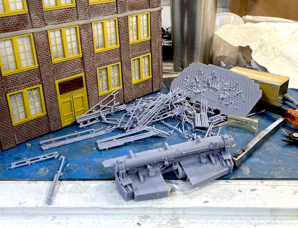
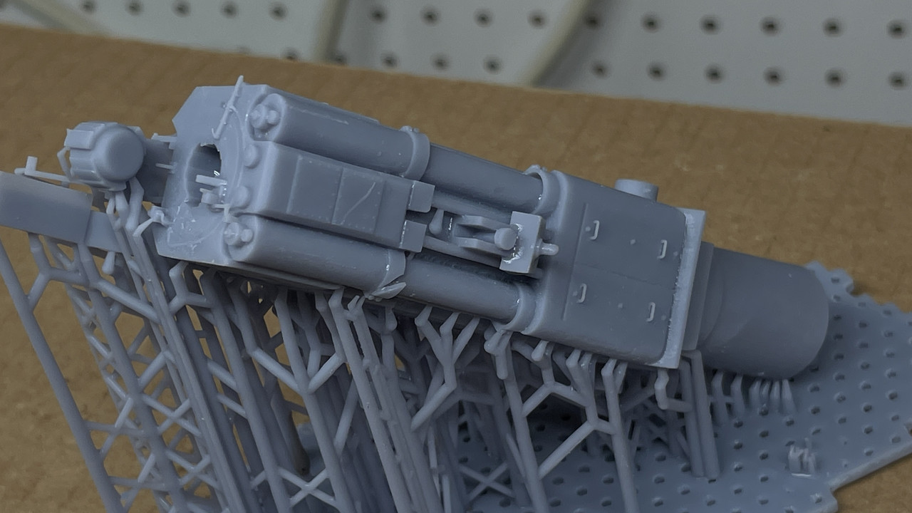
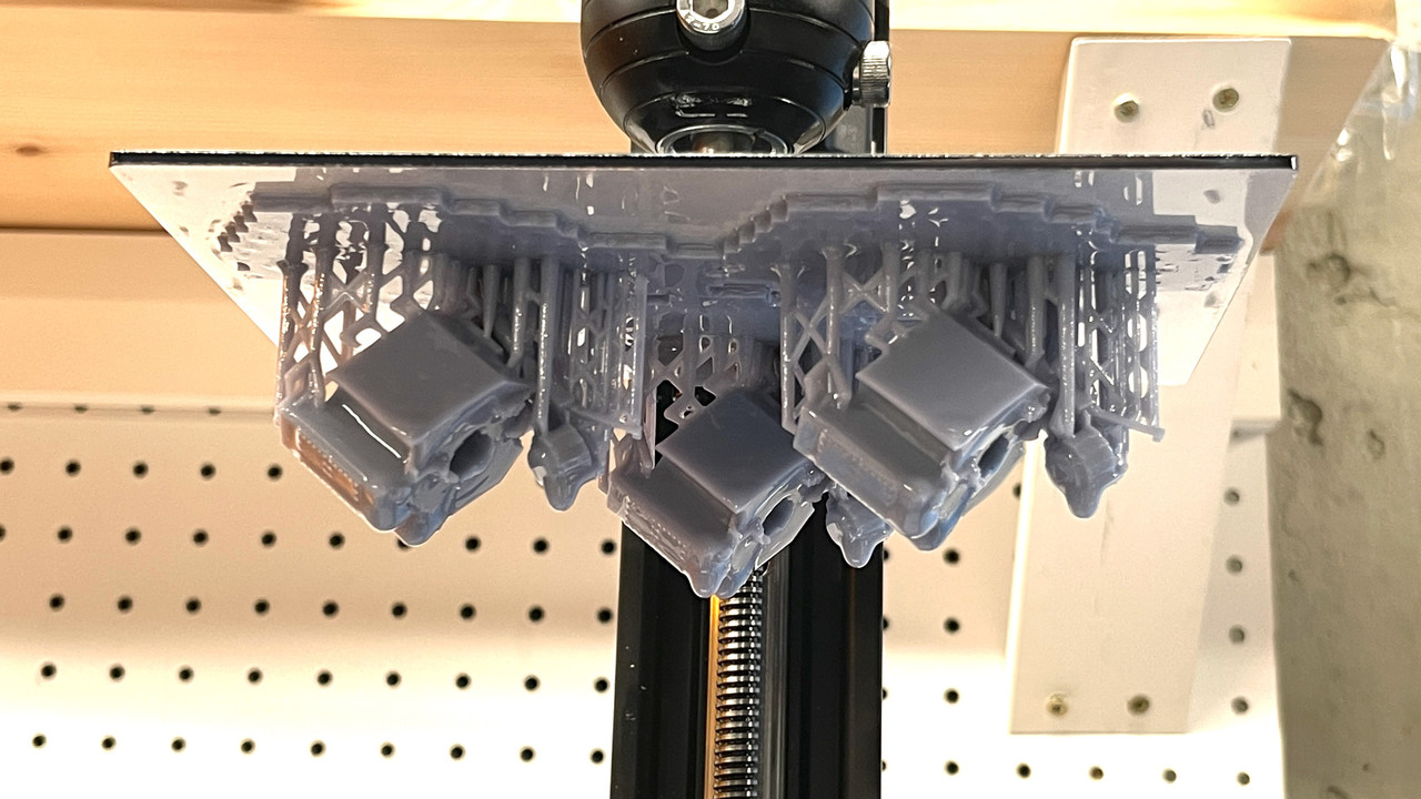
And just to give you an idea of how much work it is to remove all the supports without breaking any details, here’s what’s left after about an hour’s work. The building in the background is the next one I’m building for the railroad.
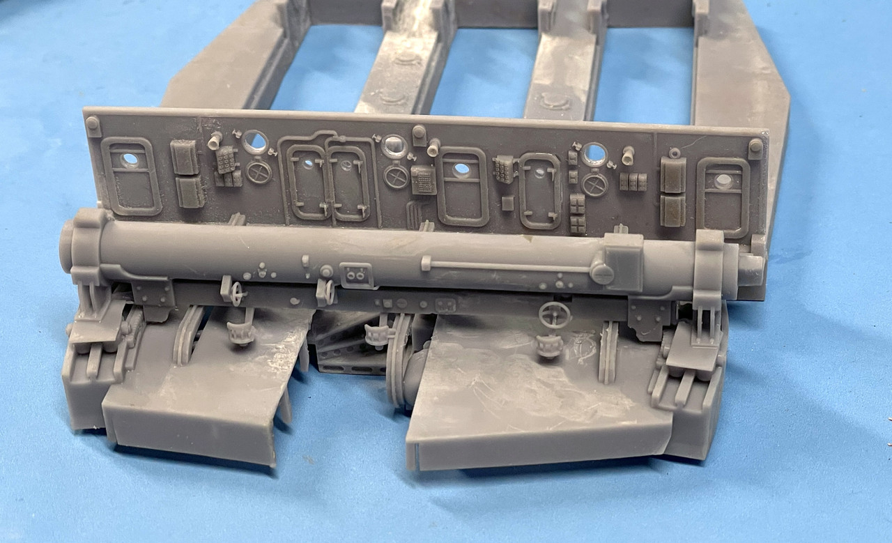
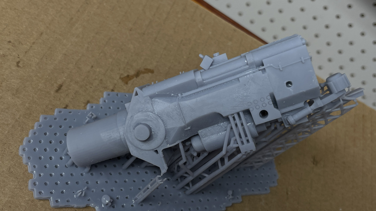
And here’s all the details underneath that wil be out of sight in the finished model. Some of this has changed with the new design. I’ll print that tomorrow.
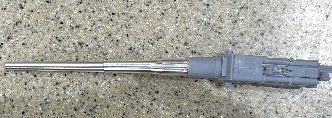
And look what else came in the mail yesterday… I was expecting this stuff to arrive in weeks. It came much faster. So I was able to get a good fix on the diameter I needed to fit the guns to the slide assemblies. I set both the closed and open-breached versions up for printing. Lots of printing over the next couple of days.
The only thing I don’t like about the guns is the bore opening does not go in very far. I will live with it. I have a lathe, but chucking up tapered parts is tricky and I don’t think it will be worth the effect. The risk is too high.
If it’s any help, the clear openings between the gun girders are 5’-10 1/2".
On other detail that might help is the top of the gun girder slopes upwards starting 7’-5" aft of the centerline. It ends 22" aft of the trunnion and 1 5/8" above. The it goes down to give access to the trunnion bearings.
You’ve got the removable plates above the shelf plate. They extend foreward at the sides to the area where the sights are. The sights are mounted on the shelf plate and there is a step up to the removable plates.
The left and center hoists are one assembly. There is a 1" (40#) plate that divides them.
I don’t know if you are including this detail but there are backing bulkheads at the front and side armor plates.
I don’t have file sharing site to show pictures right now.
I’ve done a lot of computer modeling of this area—not to mention crawled through everywhere on the turret.
A detail near to my heart is there is a 15x23 opening inboard of the right hoist. The first time I went blindly through the turret with a flashlight that is where I emerged, next to the center gun.
Those barrels look great.
BigJimSlade as in the Kentucky Fried Movie? [:P]
They stole that from me.
Big Slim you have to find a way to get those pictures too me. I’m traveling blind for a lot of this. I’m going to be getting that special tour on May 11, but I’m not sure I’m up to crawling through some of the access hatches that one is required to do in the turret.
The change of that 10’-2" center distance, cost me about 5 hours of drawing work. It changed a lot and solved some problems too. I successfully printed the first gun assembly, but had warpage. The fit of the metal barel into the slide was perfect, but the gun isn’t pointing straight.
Amazingly, the printer reproduced the hand grabs on the counter-recoil covers. The breach details came out okay too, but I went back and added some meat to the t-handle used to lift the breach to closing position.
From the side, it all looks pretty good. But from the top, it’s another story.
The twist seems to start in the trunion area and continues into the slide area. I also used the hollow out feature of my printer’s slicer program to reduce some of the resin use, but I didn’t like the results and it may have contributed to the warp. I’m correcting this by printing the gun in three parts: two slide halves and a single piece breach yoke. I’m screwing the two halves together with 4 X 10mm screws and nuts. Overkill, but i had them around. I will plug the holes with custom-printed plugs. Here’s what it all looked like. This took a lot of hours to do too. All day yesterday. Splitting the drawing was easy, closing off the back of these complex shapes to make them a printable solid took hours.
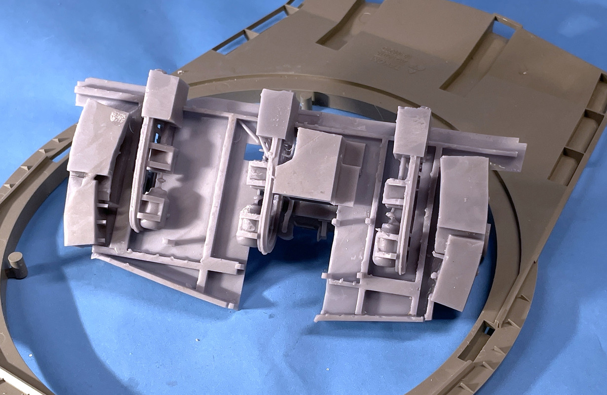
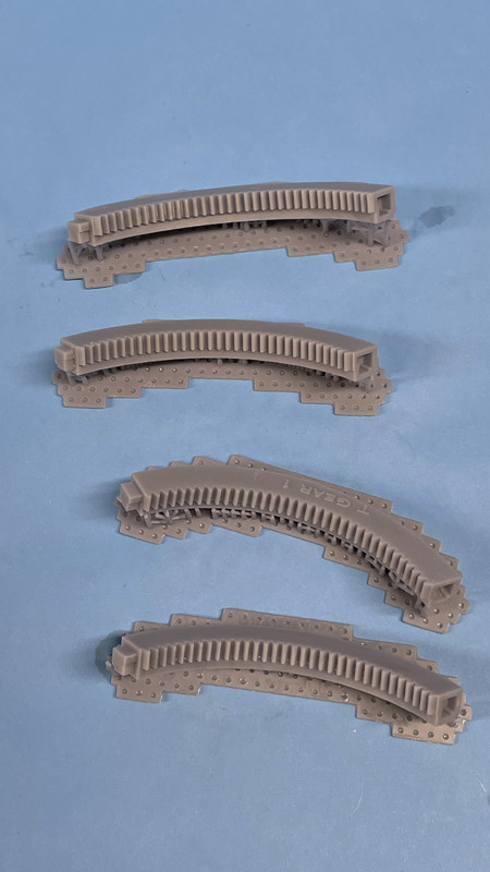
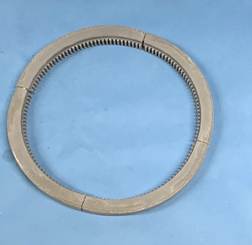
I also got a successful print of all four of the traverse gear rack ring and lower roller race.
And yes, I’m trying to include as much detail as is physcially and practicably possible in 1/72. So all the input anyone has, I’m interested.
The type of printer matters.
He is using a a resin stereolithography printer which uses a UV LED screen to “fix” liquid resin. The screen “resolution” determined the smallest amount of resing that can e “set.”
The alternate printing methos is thermal deposition, where a filament is melted and extruded through a printing head. Because the printer head has to move around, the ase material can (usually does) cool slightly. This creates “layer granularity” in the finished print.
The resin printers also “set” a “slice” ut they do it as an entire “image” (which variers by printer as to size and scale and resolution). ut, it happens faster, so the resin with “neld” together with less granularity.
That’s why you have to wash the printed parts after printing, thne “cure” them under UV light.
WHich is a “gotcha” for the resing printers; you not only need the printer, but a washing tank and a curing light are needed too. Elegoo and AnyCubic (and the like) are happy to sell their versions of those. Or, a person can just cope with having to do such things “by hand” (which means sitting with a couple of tubs/big cups of IPA rinsing them back and forth, then waving a UV light sources for as long as it takes).
Oh, and while I’m lathering on, you do not need to be a CAD wizard as there are thousands of files that are ready to print availale. Luke Towan has a uch; Thomas at LaserCreation World has a ton of diorama goodies, so, much of the work is “already done.”
There’s a roust “finished product” market out there, which our very own ModelMonkey has a dizzying array of ship-related parts available.
For true “custom” work, though, your need some sort of CAD capaility. The choices for those are legion. SketchUp, a drawing software has ecome something of a de facto standard in the modeling community, mostly as you can get into it relatively inexpensively.
It does have some limitations in building files that can e 3D printed.
Dear Capn. with all due respect, in my opinion if you want to do any useful 3D printing, you need to know at least basics of 3D design - usually more. Every time you try to get an “already done” 3D design and “just print it” problems start - there’s some problem with the STL (problems with file consistency, “holes” and stuff like that) or the orientation of the model has to be adjusted (OK, this is doable in most printing programs) but most of the time you really want something different than is provided - there’s too much or too little detail, or you want some details to look different, or you want some different version or variation of what’s there, or different pose - and the magic of 3D technoology is it can give you exactly what you want as long as you can describe it right (= 3D design).
Builder - did you try a program called meshmixer? It’s really a cool thing for cutting and combining STLs - extracting subassemblies from STLs and combining them together. This would probably have saved you those hours you needed to split those gun receivers.
By the way, I’m watching this project with a cheer, this is going to be really cool when done. I have a somewhat similar project stuck - a smaller turret, an M60A1 tank ![]() Go Builder!
Go Builder!
Good luck with your projects and have a nice day
Paweł
Good discussion. I have Meshmixer, but it’s too complicated for me to jump into. I’ve looked at some of the tutorials, but get lost in all the variables you need to control. I’ve been a SketchUp user since version 1.0 in the 1990s when it was still owned by the developers in Colorado. Since then it was bought and sold by Google and is now owned by Trimble.
Trimble got a little greedy in my opinion and screwed up a good thing. There is still a free version, but it’s only cloud based. And you can’t use any of the myriad of plug-ins and add ons that really increase SU’s power. But, SU is difficult to use to make compound curves and organic shapes. Meshmixer is much better. If you’re going to attempt to create people, curvacious auto bodies, good luck with SU. Meshmixer is where you want to be. I will learn it one of these days.
The LCD matrix printers came on strong in 2019 when Elegoo and a few others adapted a cell phone screen (and it’s associated driver circuits) to create a mask that will allow UV light of 405 nm to pass through the LCD and cure layers of photosensitive UV resin. The resin is kept away from the LCD by a clear Teflon membrane referred to as the FEP. With this tech change the price dropped 1000% from starting in the $3k range to the $300s. It was at that moment that 3D resin printing was available to the hobbyists (like me).
Regarding the rest of the paraphanalia you need, it’s not a deal killer. It’s just a bit sloppy. I have two 99% isopropyl alcohol baths to clean off the excess un-cured resin, then an inexpensive Chinese ultrasonic cleaner to remove the alcohol and any remaining resin. The cleaned resin is still a bit sticky and soft as the curing process in the printer only partically cures the resin. This is essential since fully cured resin layers wouldn’t adhere to each other. This is my setup before the addition of my Mars 3.
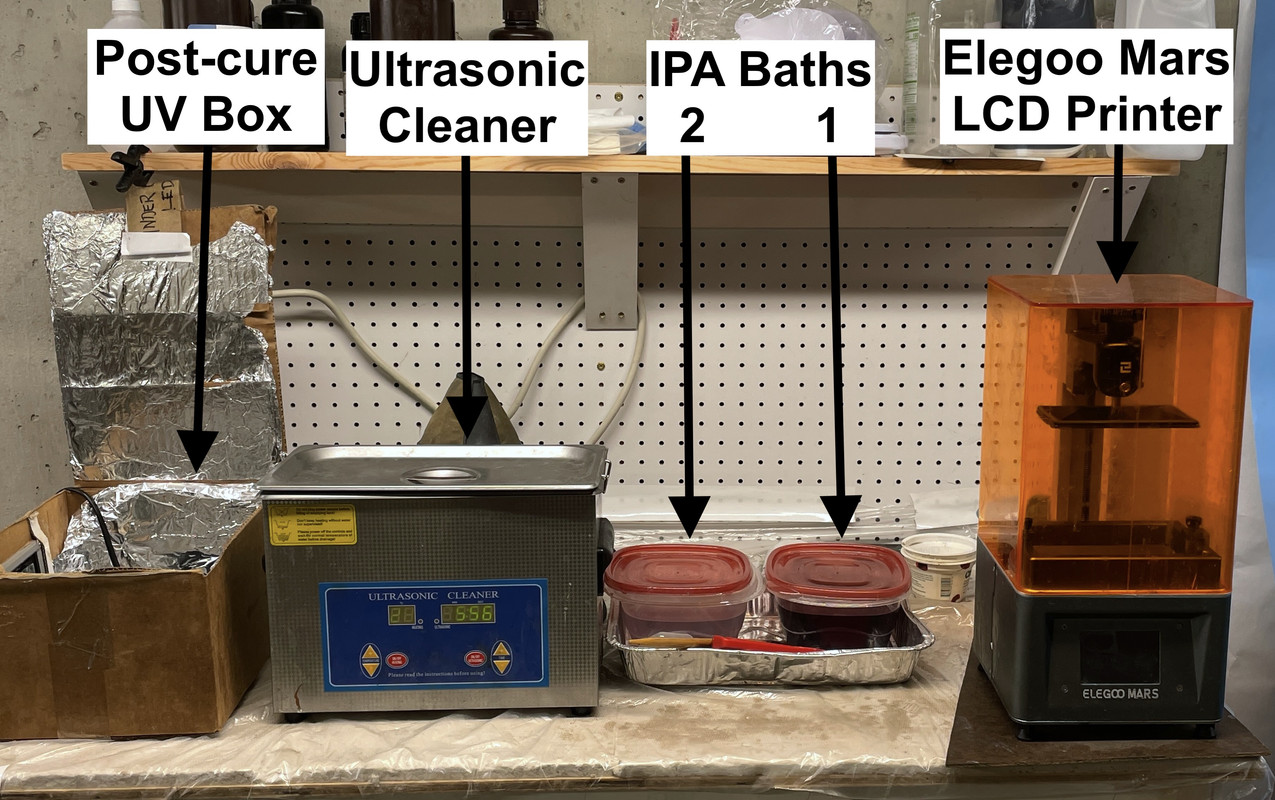
Post-curing is done in my DIY UV Curing Chamber consisting of a cardboard box lined with aluminum foil, a little turntable and a UV 405nm lamp. All the components came from Amazon. My total cash outlay for my rig is:
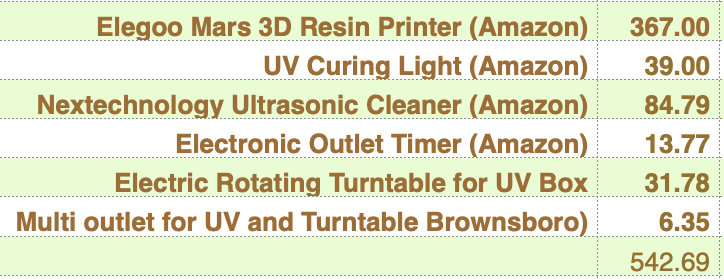
That printer was the first Gen Elegoo which I’m calling the “classic”. It’s now less than $150 and my Mar 3 was $350 with 8X the resolution and 4X the printing speed with 30% more volume.
The UV resin is a bit nasty so you need to work with rubber (nitrile) gloves at all times. The alcohol baths are messy and I have them on a custom-built work table covered by poly sheeting. The alcohol baths are sitting in a disposable aluminum baking pan. The floor under this area is a mess so don’t setbthis up where messes are forbidden. You’re supposed to do this in a well-ventilated area, but the smells don’t bother me. I really don’t smell the resin very much. All fumes are pretty much confined to all that alcohol.
I use a small amount of Simple Green detergent in the ultrasonic and then wash this residue of in a clean water rinse. After the rinse, I dry the parts with a Top Flight hot air gun originally purposed to shrink poly skins on RC model air craft.
90% of the jobs require supports that are produced in the 3D printer’s slicing sofware. These must be carefully removed to produce the final part. It is easier to remove supports before they’re final cured. Some can be popped right off by hand. Others must be clipped with flush-cut pliers or a hobby knife. For fine details, support removal is very dicey since the detail can be destroyed in the process. I’ve learned to customize my support scheme to protect detailed areas.
There are times when support removal should done AFTER post-curing. If the part is prone to warping leaving all the supports on can help prevent this. Also, you can use a hand grinder a la Dremel with needle point diamond burr to grind the supports off. This is how I removed supports attached to delicate structures. It’s easier to grind cured resin.
BTW: I’ve paid for the capital investment at least 4 fold by selling my services to others. I am not in business per ce, but capture anything that falls in my lap.
That’s enough for now. The first split gun slide is done and hanging on the printer waiting fo me. I’ve also gotten some spectacular drawings of some of the critical steel work in the turret drawn by another of my readers, Jim Palmer. It’s making me re-think some of my designs and it’s not too late. I’m spending so much time on this that it might as well be the best that it can be.
The ring gear assembly test was successful. I pushed the segments together, but not fully seated. There was some warpage with the curve of each segment tightening. I’ve given up the thoughts of having this beast actually rotate since all the cutaways would be out of sync, so if it’s a little out of round, I can probably live with that. And like an idiot I sanded both running surfaces before assembling and sanded off those nice raised lettering that identified the assembly sequence. I was still able to puzzle it together by looking how the gear teeth were split. None were segmented in the same way making them unique.
The gun slide was another thing entirely. While the print was successful (sort of) it still warped a lot. Both halves warped away from the jointing surface at each end. I thinned the slide sleeve that was to accept the gun to much. I did this so it would slip into the slots on the glacis plate on the gun house. So it kind of fell apart when I post-cured it. I screwed it together tightly using the two screws by design and another 1/4-20 bolt and nut through the trunnion hole.
You can see the warp on the right side. That one doesn’t bother me becasue that hexagonal shape is going to slip into a corresponding hole in the breach block.
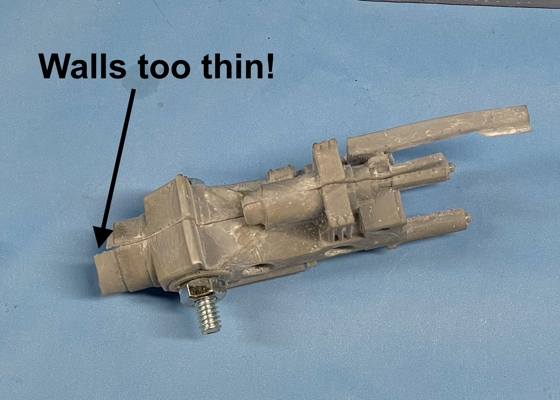
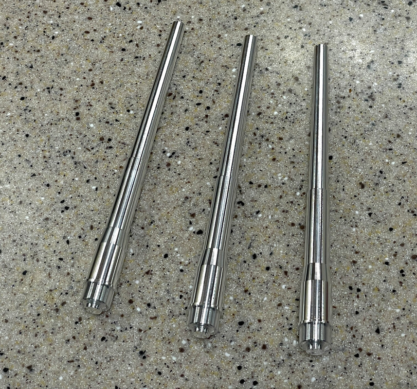
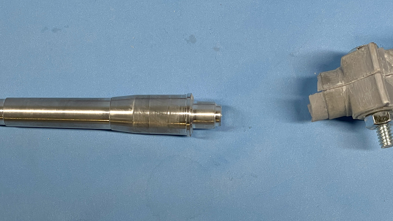
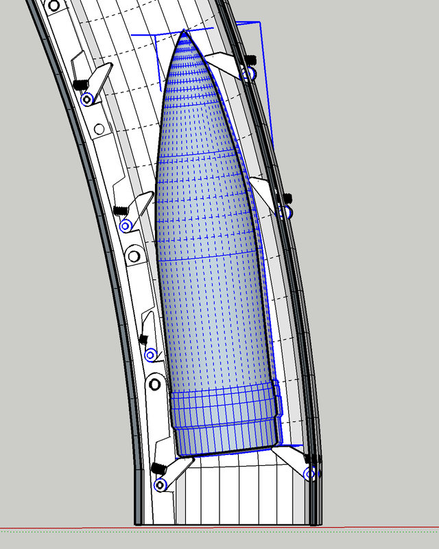
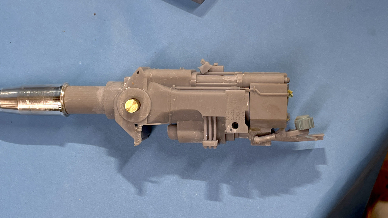
This sleeve problem required a more drastic solution. I turned down the tail on one of th guns to 7/16", narrowed the outer walls a bit more so the sleeve with fit through the .457" opening in the gun house and still give me more wall thickness so it would be stable.
I wasn’t sure I could chuck the tapered barrel into my little Taig micro-lathe. The spindle through-hole is not large enough to accept the hole barrel up to the parallel part at the slide area, but i was able to center it with the four-jaw independent chuck and use a steady rest to support the long overhanging part. I got the concentricity within a couple thou. I wrapped the chuck area with some adhesive label paper to protect the finished surface. I was able to successfully change the diameter. If my lathe was a little bit longer I could further drill out the bore, but it ain’t, so I won’t.
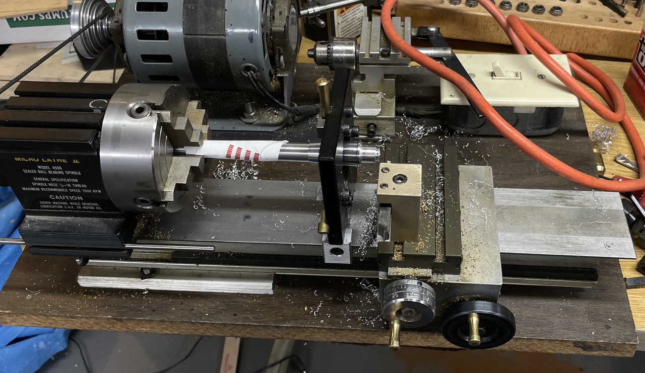
Here’s the turned down barrel. I’m not worried about the wear that the steady rest applied to the slide area. I will work that out. Actually the slide wear line go fore and aft not radially.
Here’s the reviseed design. The new design also gave me a chance to fix some drawing errors that were causing some print errors. You can see the thicker walls around the barrel entrance.
Jim Palmer, one of my faithful followers, has provided me some exceptional drawings (not SketchUp) based on actual engineering drawings of some of the critical structural areas that are very ambiguous on the illustrations that I have. He’s going to get me some dimensions to make these more usable to me. One of the big “AHA’s” was the edges of the gun girders form the partition plates in the pan deck. I can make this modification. I just need some measurements to firm up the final shapes.
I haven’t re-printed the revised gun girders so I can simply change the notches for the styrene plates so they’ll be the full depth.
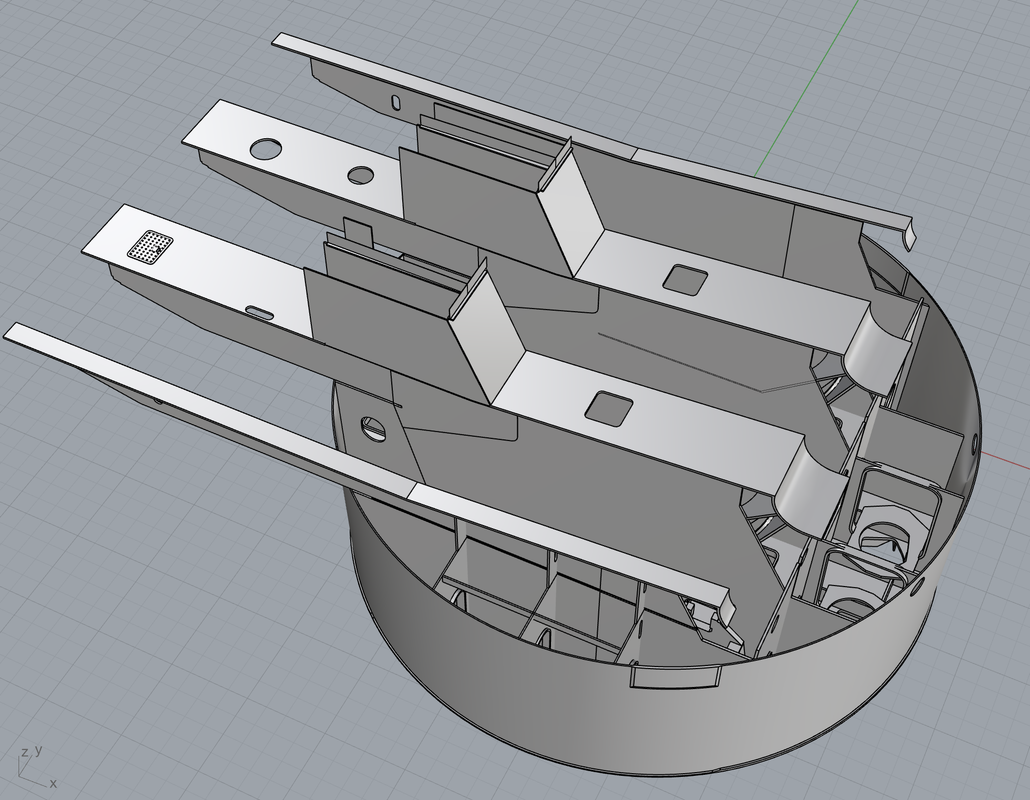
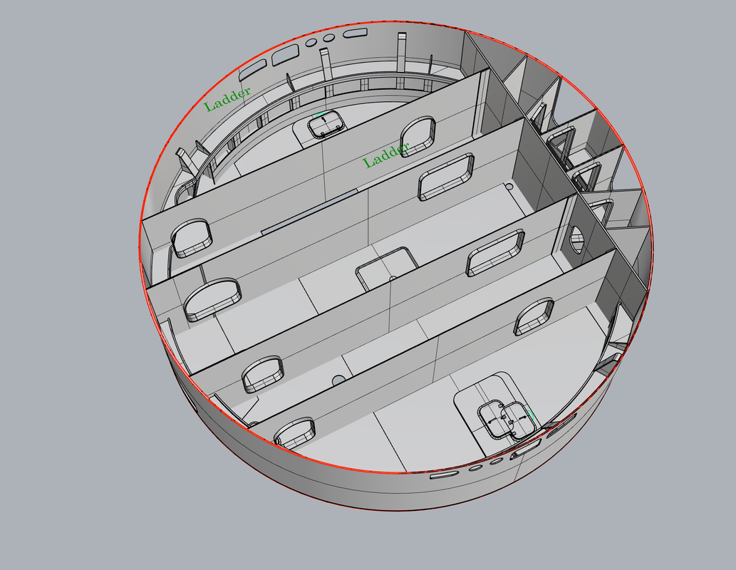
Here also detailed the pan deck floor showing the exactly location of the gun pits and the various hatches used to get from one place to another. You can only actually enter the rotating parts of the turret in two places: the hatches underneath the gun house from the main deck, or entry through the powder flats at the turret bottom. All other access is by vertical ladders and quite small hatches. For these reasons I’m seriously wondering if I’m going to physically be able to go through all these spaces. Noticce the two outer access hatches are actually in the gun pits themselves.
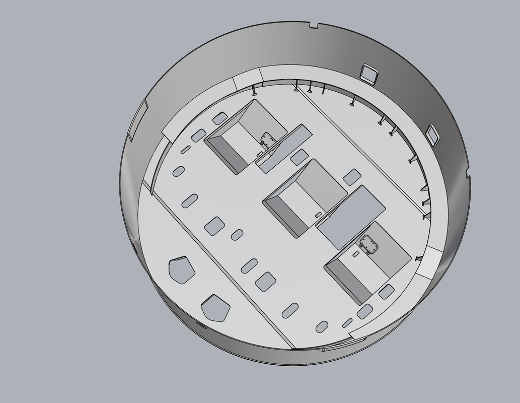
What’s even worse is the electric deck.
The Electric Deck is fully partitioned and you can’t get from one partition to the other. You must go either up or down and then across. It’s like the Super Mario Brothers game. Luckily, I have done nothing on this deck except the outer walls so I didn’t waste any effort. And then there’s “how to show this interior?” There are four work stations in these partitions: one person manning the manual training (traverse) station, and one each manning the manual pointing (elevation) stations. It must have been pretty longer in those claustrophbic work stations in the bowels of the turret. All of this deck and the pan deck rotations with the gun house and the guns. When you get to the projectile decks, the outer portion is fixed. The next ring with the projectile hoists rotates with the turret sicne the hoist chases are fixed in their position to the gun compartments, and the inner ring is rotated independently with it’s own power system and circlar rack and pinions… sort of miniaturized version that rotates the turret itself.
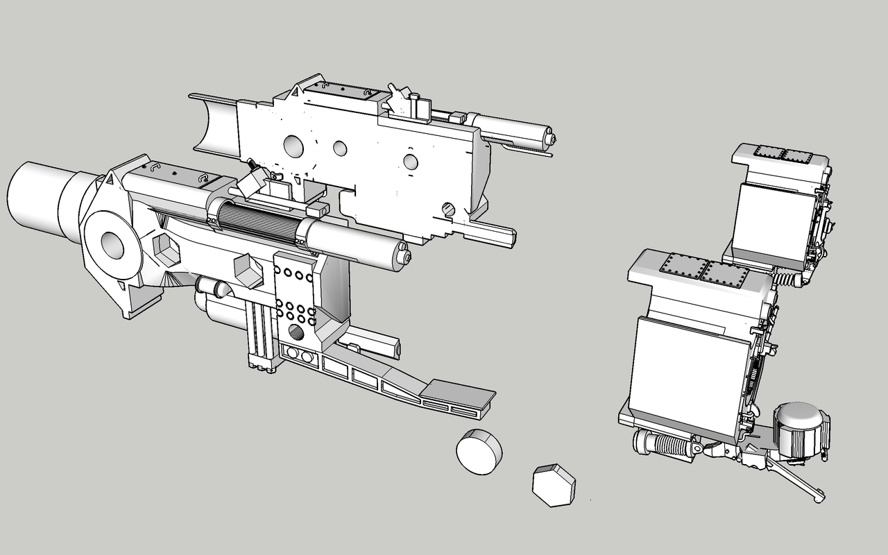
I finally figured out how the projectile hoist actually works. It was somewhat difficult (for me) to puzzle it out since I was expecting an elevator arrangement like the powder hoist. But when you think about it, this wouldn’t be easy to do since the cradle that accepts the projecile is open at the top and there’s no cable pulling anything up.
Instead the mechanism consists of a moving rod that has spring-loaded pawls that engage under the forward side of the projectile’s bottom, and another series of spring-loaded pawls that pop out of the projectile hoist chase opposite to the moving rod.
The moving rod is stroked up and dow by a hydraulic cylinder (for those so inclined, the first part of this sentence did not talk about what you might have thought it was talking about). When the projectile is pulled into the hosit base via the par-buckling rope it passes through two spring loaded doors preventing the projectile from re-entering the projectile handling area. The hoist rod starts moving up with the spring-loaded pawl extended and it hooks under the projectile lifting it up the length of the piston stroke. As it reaches the top of the stroke the projectile has been passing by the pawl on the oppositie wall which pops out beneath the other side of the projectile’s bottom preventing it from falling back. The moving rod retracts downwards bringing the next pawl (retracte) along side the projectile where it pops out at the bottom grabbing the projectile and lifiting it the next stroke. This continues until the projectile enters the cradle which also has a pawl that snaps out grabbing the projectile and preventing it from falling back. The projectile is stable in this position and ready for loading the gun.
With this method, you can have more than one projectile on the lift at the same time. In fact, in order to load the gun every 30 seconds, you could not wait for a projectile to rise four decks and be ready to load. While not an actual drawing, this is my interpretation of how the pawls interact to move the projectile from the projectile flat to the cradle. The moving track is on the left. The pawls on the right are somehow fastened in pockets in the projectile hoist chase wall. That detail is not essential to understand the mechanics.
Wow. So much information and skill being presented. Thanks to you and the discussions of various aspects of 3D modeling/printing/designing et.al. I am at last just barely beginning to understand what this type of modeling is about. So thanks again, this is a grand project.
You and I will be on similar sorts of “pages” as to what we would expect (or demand) of our 3D software. I know I’m biased from being neck-deep in CAD sofware since 1983.
But, we represent specific cases, the world is far more general; I know of many who are more tolerant of things we likely would not abide. As the kids say “The Struggle is Real.”
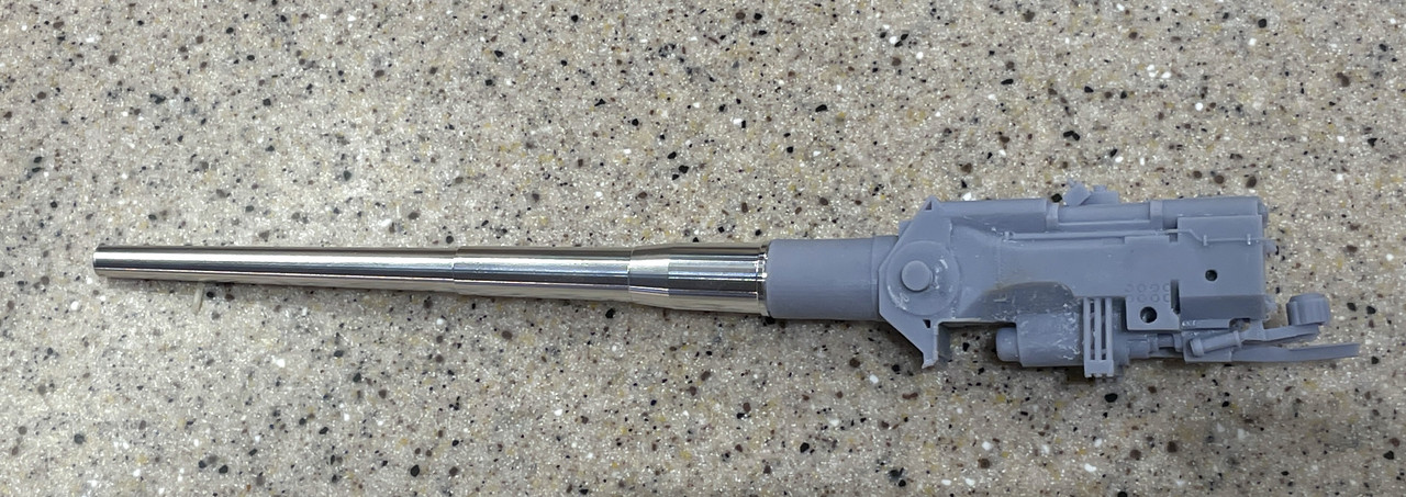
I have said many times before, I am not particularly patient, but I am persistent to a fault. And persistence what was called for in making a functional slide assembly. My fifth and sixth prints were completely successful. My fourth was a correct design, but I didn’t get it loaded correctly in the printer and part of it failed. On number five I let the printer slicer software (ChiTuBox Pro) auto-position the part on the platen.
It was a bit counter intuitive to hang it like this. Normally you set it at around 45 degrees to minimize the surface area on the plate to reduce the suction forces that tend to pull the part off the plate. In this case, vertical was the smaller foortprint and it left the delicate counter-recoil and gun captain platform basically without any supports at all. No supports is the best case scenario since supports cause potential surface defects.
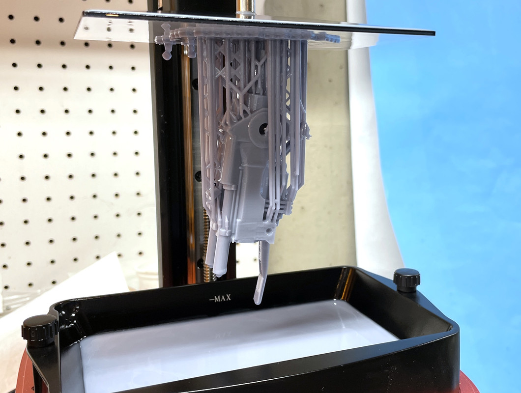
I had to drill out one of the hollow access holes on the part to help clean out and drain any unexposed resin trapped inside. My slicer-drilled software hole wasn’t deep enough to connect with the hollow chamber. After drilling it into open space, I used a large syringe to flush alcohol through the insides and clean it out. I then put it in the ultrasound and afterwards used compressed air from one of my airbrushes to blow out the remaining liquid.
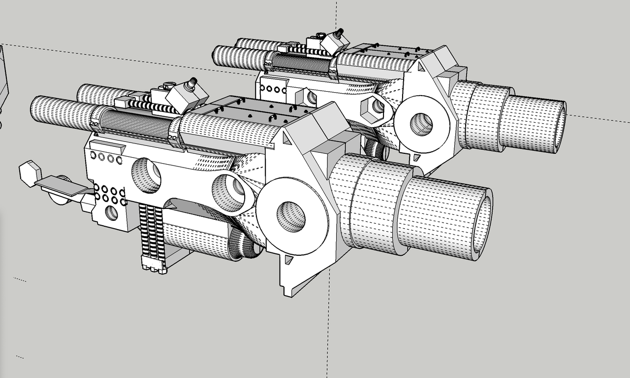
I machined the other two barrels down to 7/16" and now have three good, warp-free guns. it took a lot of trials and wasted resin, but without the guns the entire project was up for grabs. The guns are the essential focal point and are neat models all by themselves. All the gun point in the right direction… straight ahead.
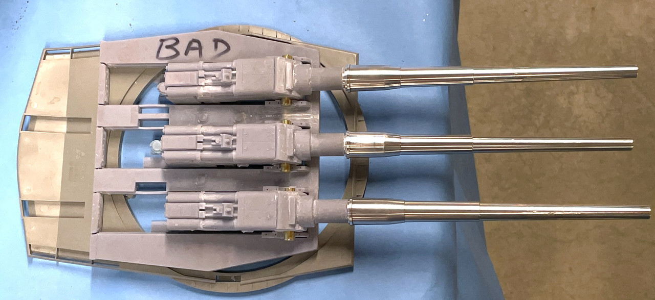
The two guns with the open breach are right-side loaders and will be set at the 5° elevated load position. The remaining gun is a left-loader and will have the closed breach held in the 45° maximum elevated firing position.
The side of the gun is nice. The only details that got whacked were the tiny hand grabs. They had supports on them and removal of the supports broke off the handles. I’ll make new ones out of fine wire. I have plenty of rejects on which to try out making them.
The yoke with the open breach on the back of this gun is not perfect. I’ve printed three more after fixing the drawing. They’re done and hanging on the machine for clean up tomorrow. There were some improper faces on the bottom that failed to print. I found the errors and corrected them.
Work is continuing on the pan and electric decks. I’ve got the partitiions laid in on the electric deck. With the partitions in place I can start laying in the equipment. I’m also wrestling with the rear area of the gun compartments. There are lots of hydraulc controls on those walls for the cradle, the rammer and the gun captain’s communications devices.
Oh yeah, those babies look especially impressive side by side! Good luck with your design and have a nice day!
Paweł
This is such a great walk-through of what it takes to actually do the 3-D design work and get a part to print that is accurate and usable! Beautiful work. Gonna be an awesome display!
Hello!
I’ve just found this picture online:
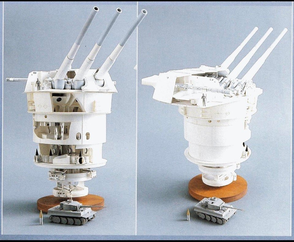
Had to think about your project immediately - and I thought I’ll post it here, maybe it will give you an idea as to the presentation of your work?
Have a nice day
Paweł
Nice picture Pawel…
Builder2010 - Ive been following this with interest - what a great write up. Thanks ! and thank you for the pictures too. Im interested in 3d printinf but done nothing with it. How does the resin come and how much have you gone through so far? Expensive??