1:72 Iowa Class Mark-7, 16"-50cal Turret #1 with Custom Interior Start-to-Finish

This thread inspired me to watch a few youtube videos on these big guns. Crazy close quarters and tiny hatches. These things look gigantic from the outside. I recall touring the USS Pampanito in SF (Balao class sub) and was floored by how tight/tiny things are. Same when I did a walk thru on a B-17. Brave men with zero claustrophobia!

Great progress.

For some reason the FSM forums were off line yesterday. Thankfully, today, they’re working again.

I’ve finished the detailing of the gun loading equipment and started working on the bulkheads and other machinery in the gun house itself. I was able to do a pretty close job on the powder doors after finding another good diagram. Here’s some status shots. Remember, the turret walls will be from the kit.

And a rendering of same…

I have to figure as I go on just what walls will be cutaway, or transparent to show all the cool stuff that going on inside. For example the machinery that runs the powder hoist is an elaborate electric driven A end/B end hydraulic hoist system that’s located on the gun house floors between the bulkheads behind in front of the powder hoist chase. In fact, almost all the systems that run the turret are similar electro-hydraulic system with a motor-pump and remote actuator. This includes the traverse, elevation, and all the various hoists. I plan on detailing as many as I can.

Ryan, over at Battleship New Jersy is pretty responsive to comments on the YoutTube channel.

They also have some cool video from the turrets.

That beign said, Iowa recently had a video of them lowering–manually–one of he guns, which has extensive video of the inside of the gun house and the side walls.

Neither can I. I’m still waiting for the darn kit and guns to arrive at the hobby shop. It could be built without the kit at this point since I’m detailing so much of the stuff the kit has as well as all the stuff that isn’t. Earlier this week I got the lead screw elevating gear drawn. I found a good lead screw on the SketchUp 3D Warehouse and elarged it to be battleship-sized.

Today I finished up the traversing gear. This includes the B-end motor and gear boxes on the pan deck and the action ring and pinion gears protruding from the electric deck. My pinion and gear set has bigger teeth since it has to be able print in 1:72. And just for fun I figured out how to make rifling in the big guns.

Next up is a massive amount of equipment on the electric deck and finishing up the detailing the main gun houses. Interestingly, there was a manned station on the electric deck with a hand wheel a la those found on 40mm quad emplacements. These were manual stations to elevate the guns. There were three stations, one for each barrel. In the recent video “Raising the Iowa’s Guns”, the mechanics were using pipe wrenches on the shaft that goes to a bevel gear in the coupling between the elevating nut housing and the hydraulic motor. It was very slow going, but one deck below is the station with hand wheels to crank the guns up and down when the hydraulics were unavailable. It had to be a rough job to hold, sitting in a compartment with a load of electro/hydraulic machinery running and basically doing nothing unless something is not working.

Here’s a view from below show the traverse pinions. As I said, mine are a bigger diameter and larger tooth design than the prototypes. The teeth at the scale the model will be are too small for successful printing and eventual use. It thought drawing the gears would be difficult, especially the ring gear. I have a SU externsion to draw volute gears. To draw the ring gear I drew and external gear of the same diameter as I wanted and used it to “cut” the ring teeth by using the INTERSECT FACES selection to embed the teeth shapes into the ring gear blank. I then pulled it to the thickness I needed. I used the same pitch size for the pinion gears. I had to experiment to get the right diameter to mesh correctly.

And using the same technique I was able to create the rifling. This time, I used the actual rifling count (96) to create a ring gear, pulled it to make it deeper and then added the twist. Was really easy.

wow stupendous work! I’m learning alot reading your thread. You really are going to have a salable product when you’re done. No need to wait on the kit lol

you are the future of modeling in this hobby!

Hi;

May I humbly suggest the following. For the port or starboard half use The Clear sheet obtained from C.D. boxes. That way we can see all your hard work. You can use .010 for the round parts. jus’thinkin?

Thank you very much. I’m encouraged by the reaction of my followers.

Good suggestions. I’m leaning towards 1/8" clear acrylic due to it’s flatness and optical clarity. For the rotating lower parts, a cutaway may be used along with the transparent parts. The building is going to be as complex as the drawing, I’m afraid.

I got some more images of the floor area in the officer’s compartment from Ryan the Curator. It turns out that the reason it was ambiguous (to me) was the flooring plates are removable so they can get to the buried ramming machinery. It was the buried rammers that didn’t make any sense to me. The floor is supported on some legs and trusses. It’s pretty deep and it has four steps to get to the operating level. Here’s how I interpret it. The rammer is exposed in the trough from the entry hatch. I still think it’s not completely accurate. I think the steps begin closer to that bulkhead. Unfortunately, their location is not shown on any floor plan I’ve seen.

While there is more and more wiring and piping that can be added, I have to keep in mind that we’re printing in 1:72. If it was 1:48 or 1:35, it would be a whole different deal.

Onward and upward.

Another benefit, 1/8" clear material scales to a 9 thickness, to give a sense of the construction of the turrets. 3/16" would be 13.5" in scale–but finding the good optically-clear material will be harder.

Having the clear parts almost suggests a diagonal “cut” of them, more like a cut-away drawing or “x-ray” sort of view. But, that introduces a level of complexity probably not wanted for this project.

This point in the process is probably where a decision about “which” Iowa turret to model. New Jersey did not have the elaborate ventilation systems of her sisters (Nissouri with the most complicated batch of ducts and vents; Iowa’s scabed on as a refit)

I suspect that ther ewill be a bit of a hiccup when the kit parts actually arrive and fail to reach the present level of SU-modeled detail. The Bruno and Yamato turret kits have been interesting to watch being built as they are largely “outsides” only kits.

All good points. I too was thinking that the acrylic could simulate the armor nicely. There’s a good source of it in Louisville. They might even cut it for me. I could also laser cut it at the University of Louisville’s public access First Build Maker’s Shop sponsored by GE Appliances. They were closed during COVID, but have since re-opened.

The kit is just the exterior and is the usual styrene thickness. It’s why I can really finalize a lot of this until I have the actual interior measurements of the kit. At the rate I’m going, I may not even need the kit. That could enable me to enlarge the scale a bit (1/64"?). I would have to have the barrels turned in a machine shop (or the maker’s space since they have a complete industrial machine shop there.).

The kit is the WW2 Missori turret #1. All the Iowas had their #1 range finders removed in the '86 refit. It’s the only one with the little railings on the roof. I will have to base my visit to the USS NJ in April on either turret #3 or 2 which still have their range finders. Not sure what to do will all the ventilation gear since none of my drawings show much of it.

Since the SU drawing is 1:1 scale, all scaling is done when I export the STL files for 3D printing.

I just spent two days building the support system for the massive range finder tube. My first attempts where what my mind’s eye “Thought” was the shape of the parts. I was completely off! I erased it all and went at it again. This time it’s pretty close. Having no real-world measurements or working drawings with dimension, the whole deal is a giant SWAG (simple wild ass guess). The support system is much more complex than I originally envisioned.

All the rolling surface are bronze or brass.

I’m getting pretty good at drawing sector and pinion gears. The gear teeth on the prototype are probably half the size and twice the tooth count, but I’m always thinking about what will reproduce in 1/72 on my 3D printer. I’m thinking of printing the enitre range finder in two parts mating in the center. All depends on how I can support the parts in the machine.

There’s still more to do on this part. I have to put in the three operating stations with their handwheels and optical sights. There needs to be a way to operate that pinion also. And then there’s the outer ends with the optics, weather seal and outer gates and their controls.

Several imortant things brought up there.

Having to decide not only which ship, which turret, but having to select a time frame as well.

Scale is another. Going away from 1/72 means having to eschew easy-to-find firgures for scale. But, being able to “see” the detail matters, too.

Turning metal barrels at 1/64 may get interesting. The quarter-inch ID probably “hitting” available tube stock diameters, but you may run into issues with having ehough tube thickness to get the contour in. And having to “make up” the thickness with telescoping tubing can be an issue for turning later.

Turning from soid stock possible, certainly, but getting that 0.25" bore through 12.5" of stock will be a delicate task on the lathe after getting the contour in to scale (and leaving enough room to get 3d printed rifling in, too–as button or star rifling cutters, to scale is a bit boggling).

Which brings up the prospect of simply (“simply” o_O) printing the barrels. Which would want a printer with a 320-325mm distance capacity.

Hmm, just had a thought about finding a resin printer and using clear resin for casting some of these parts. Last thing this project needs is more complexity [:)]

I may use the clear resin for some aspects, but going with a bigger scale will have to wait. The model and guns arrived at Scale Reproductions and I’m picking it all up today.

Continued design and have the range finder complete except the weather seals at the wall openings. These weather seals are a soft barrier that’s going to be pleated. It transitions from the rectangular opening in the turret wall to a round shape around the RF tube. This is a very hard shape to model in SketchUp. I’m thinking to shape it out of Sculpey or Milliput and then model a flexible latex shape over it.

Here’s the complete rangefinder. The operators’ seats are going to be very small in 1:72, so we’ll see how they print. I may have to eliminate the spindles holding up the back. Again, not having a true perspective of all the details on the RF so the distance and spacing is all guess work.

I’m about ready to do the Electric Deck and the manual aiming stations on the turret level. That’s going to be fun since I have no actual pictures of this apparatus. I’m in the process of scheduling my more comprehensive visit to the USS New Jersey accompanied by the Curator in early May. I don’t want to start printing anything until I have final sizing complete. That said, I probably can start printing the guns themselves once I have the model in hand. I’m thinking about laser cutting some of the acrylic walls, and may be able to do this myself at the University of Louisville’s Makery. We’ll see.

As I’m writing this, I did pick up the model, but not the guns. I may use the kit’s 2-part plastic ones. My hobby shop owner didn’t know how to get the metal ones. Having the model in my hands enables me to get some actual measurements directly and modify the drawings as needed. My LHS owner asked if The model and guns arrived at Scale Reproductions and I’m picking it all up today.

I also thinking, based on another suggestion by Marty (the plastics manager at the LHS) to installed acrylic windows in the skin instead of making an entire face out of clear stuff. The model has the entire house exterior as a single part! That makes it a bit more difficult to make entire faces out of clear acrylic.

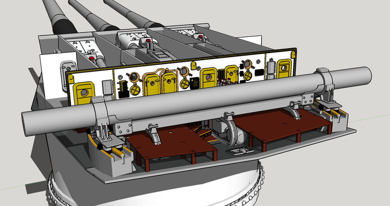
I brought the kit home and finally had the chance to see just how off my drawings were. To my surprise, they aren’t too bad. The main error was the overall turret plan shape. The model turret was a tad (.08" narrower), but different in length by more and the angularity of my drawing was a bit different. All in all, really close. All the apparatus I’ve designed so far will fit as it is.

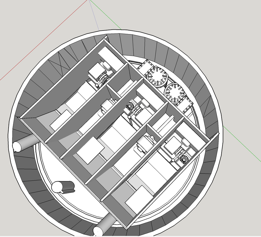
The kit’s bottom plate besides not actually being an accurate floor, has a huge opening in the middle which must be closed. The only holes in the turret floor are the rectangular openings for the gun’s motion (elevation and recoil), the chases for the powder and projectile hoists.

I measured the circular opening, downloaded what I already had from SketchUp since the openings in the floor were set by the gun’s design, and drew the filler piece to close the hole. The hole is rimmed by a 1/16" ledge, so I will either have to get some 1/16" styrene sheet or double it up. I may choose to make the floor and filler pieces out of transparent stock so you can view what’s below, but there’s some much stuff on the gun room floor you won’t see much that way.

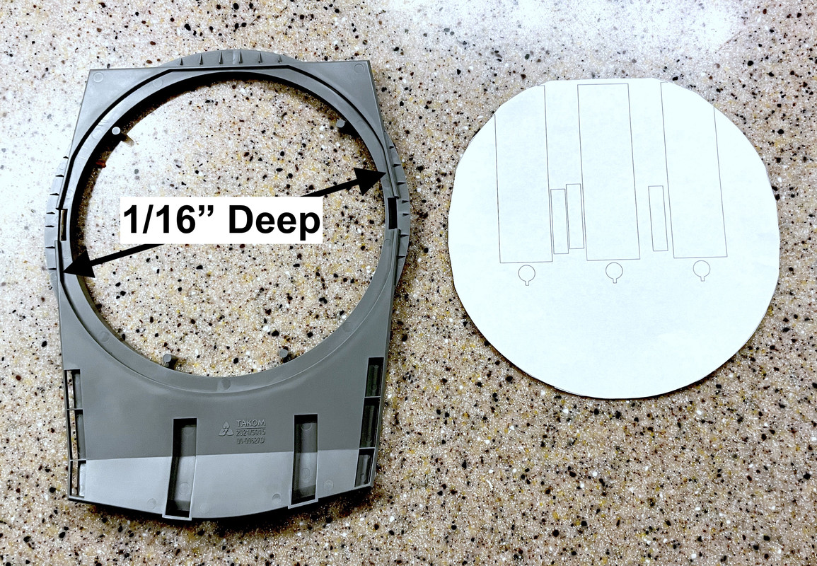
It’s not full circle with parts cut off with some angles, but that’s not a problem.

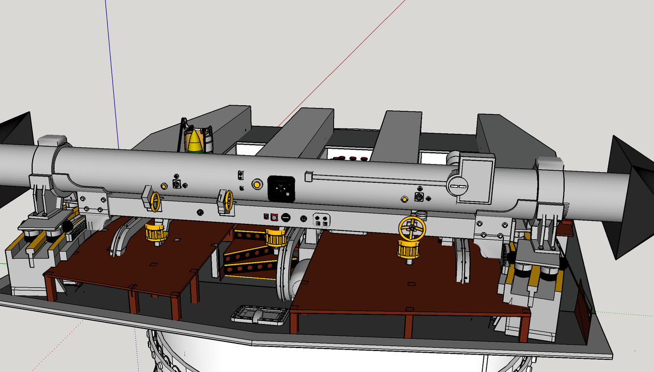
Here’s how the template fits into the hole. Notice how the gun slots are going to be outside the circle meaning I will have to cut the kit part. I may also have to shorten the slot’s length so it stays within the turret’s perimeter. The front gun shield swings down into that space so I have to watch the clearances.

Over this filler will go another flat sheet to provide a smooth floor surface for the entire gun house. This too was created by measuring the space and then printing, adjusting and printing again. It’s really nice to have the kit!!

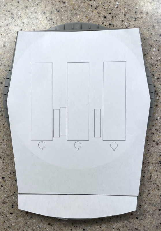
Notice that I’m making it in two parts since the turret’s rear has a kickup angle. I supposed I could scribe and bend the styrene to make the angle. In fact, as I’m writing this, I’m thinking that could be better.

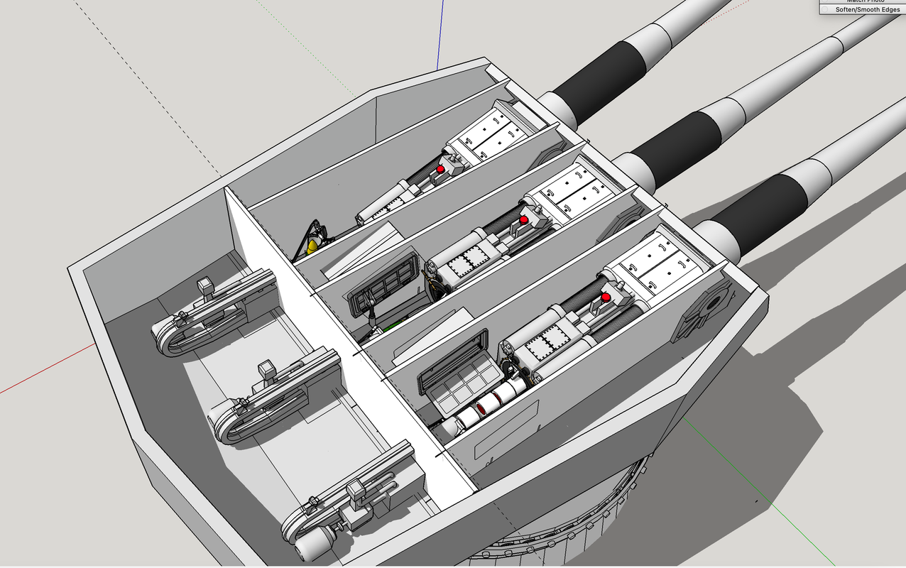
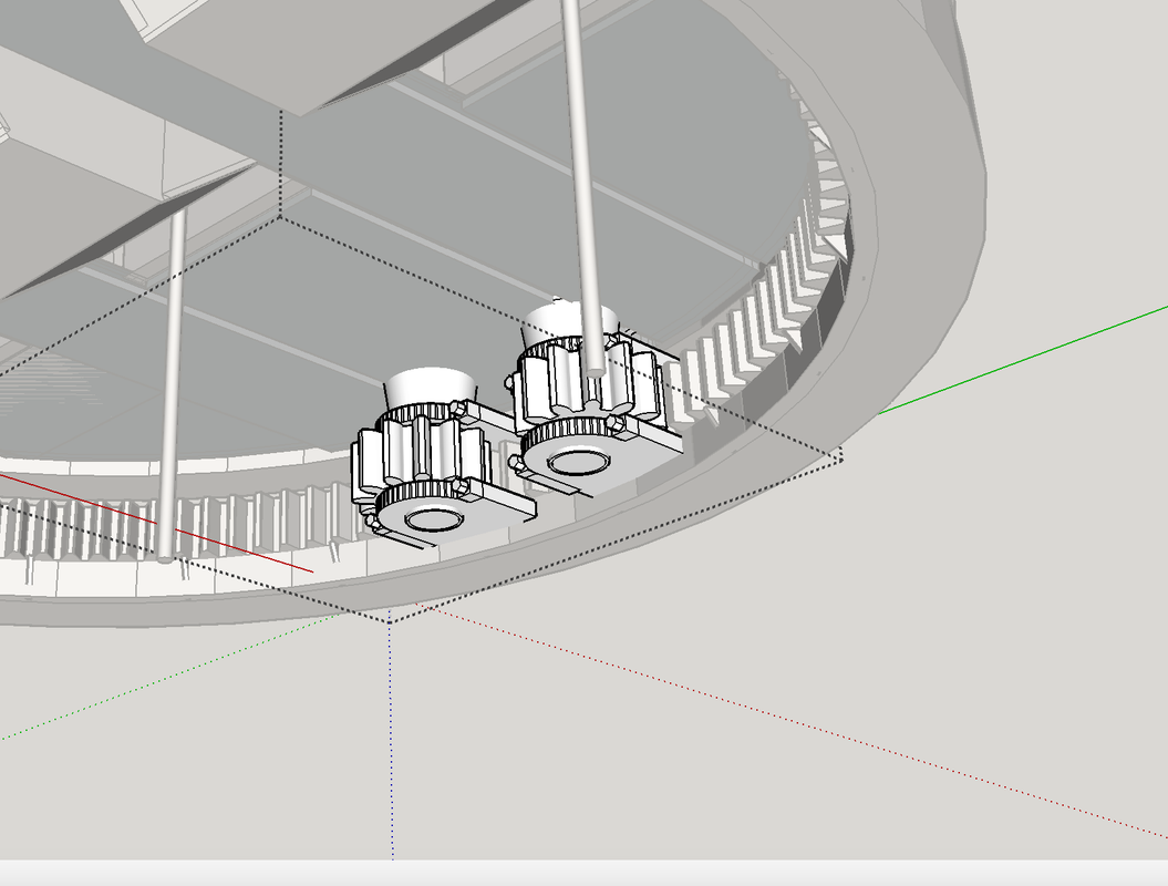
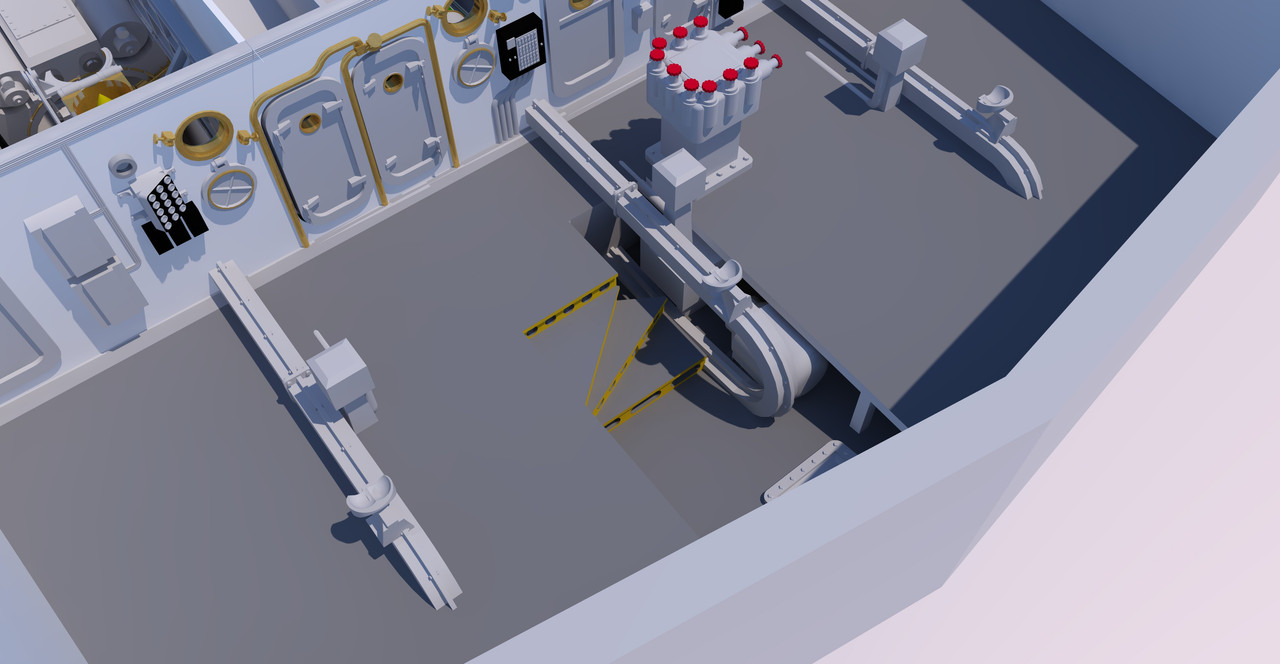
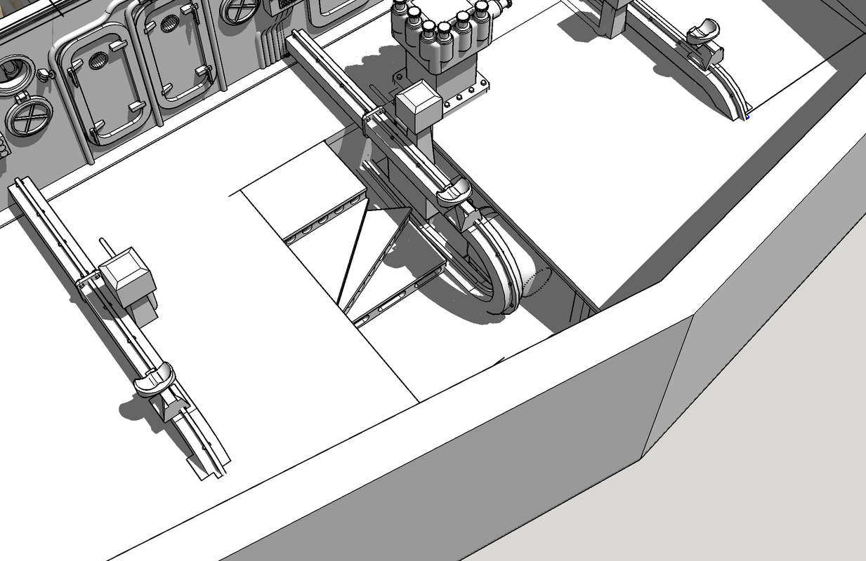
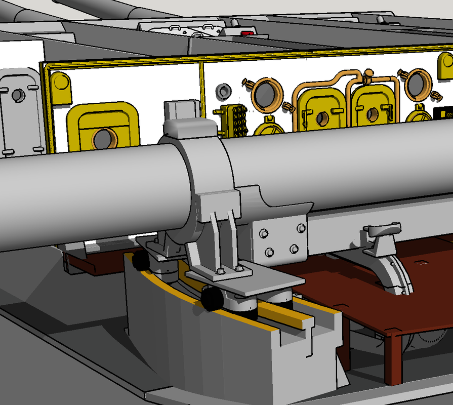
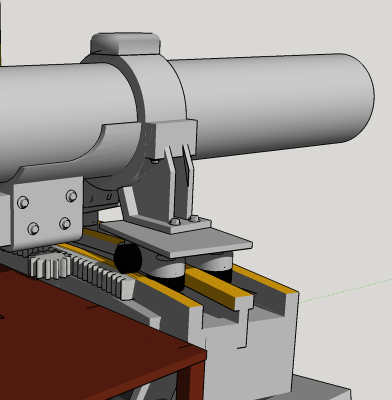
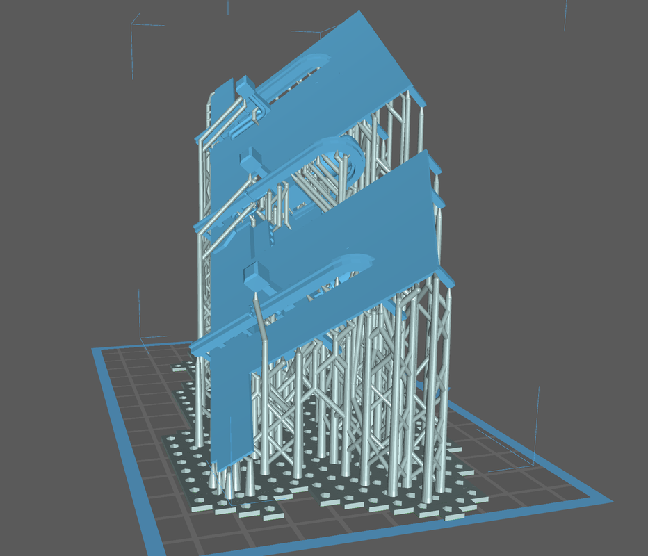
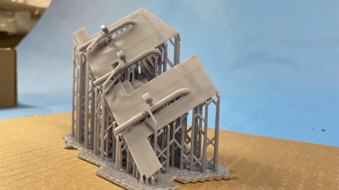
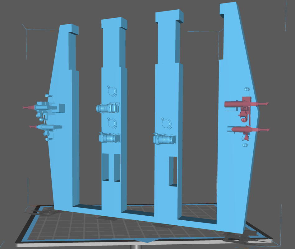
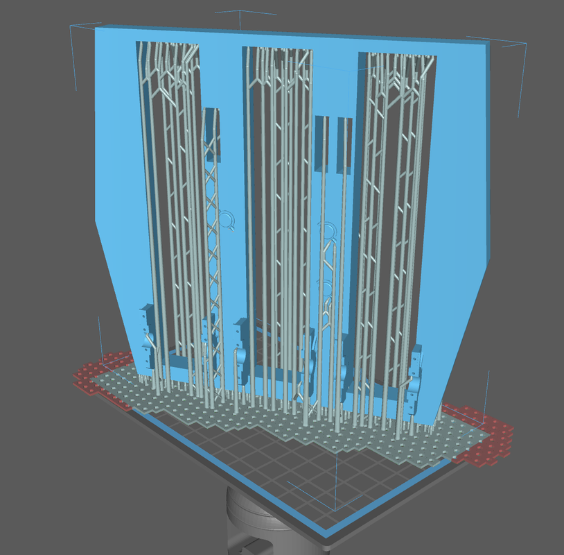
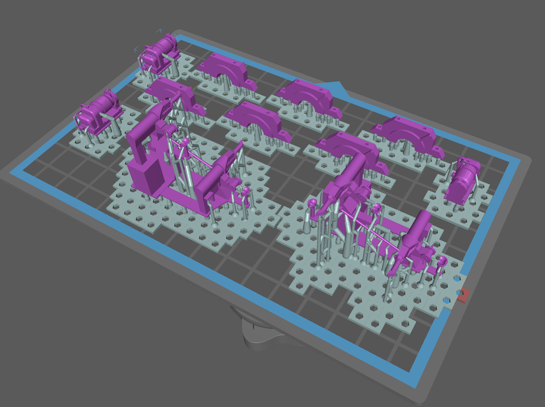
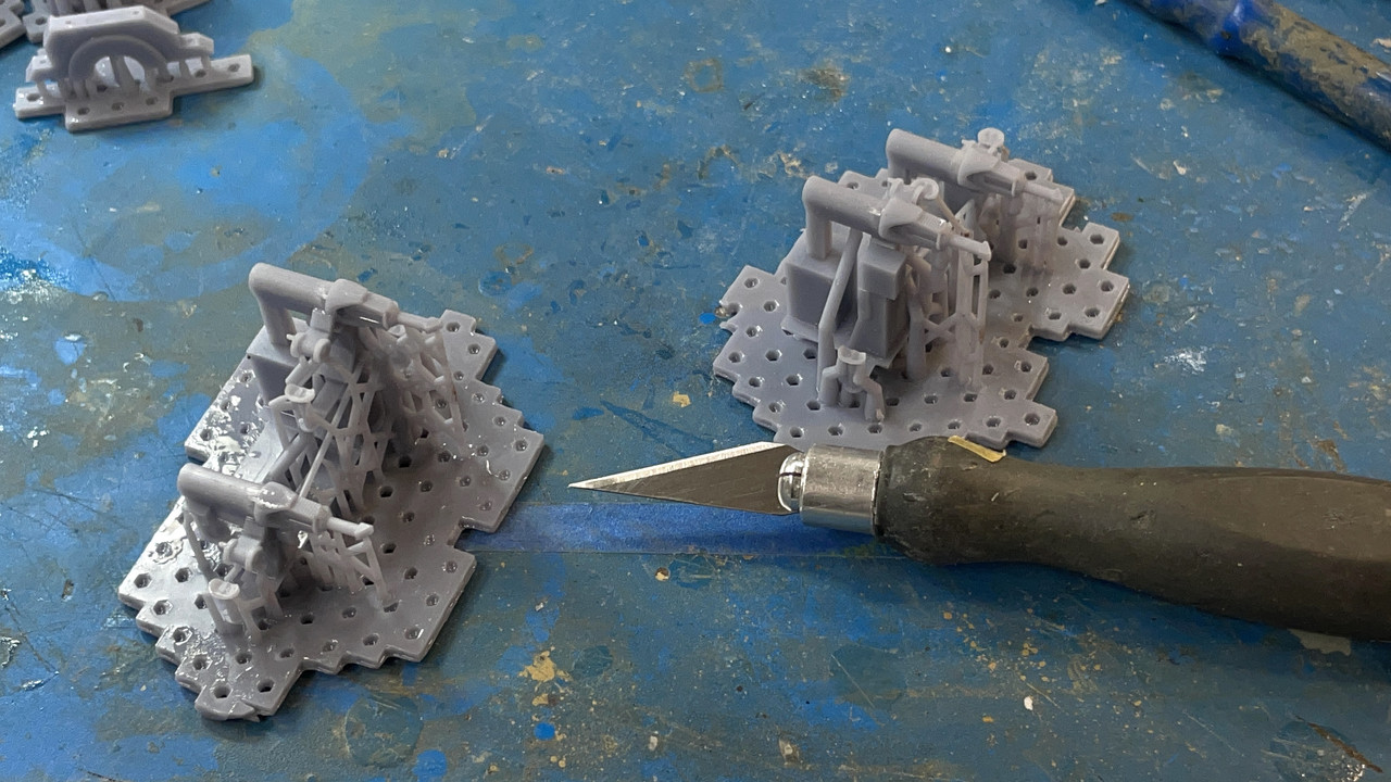
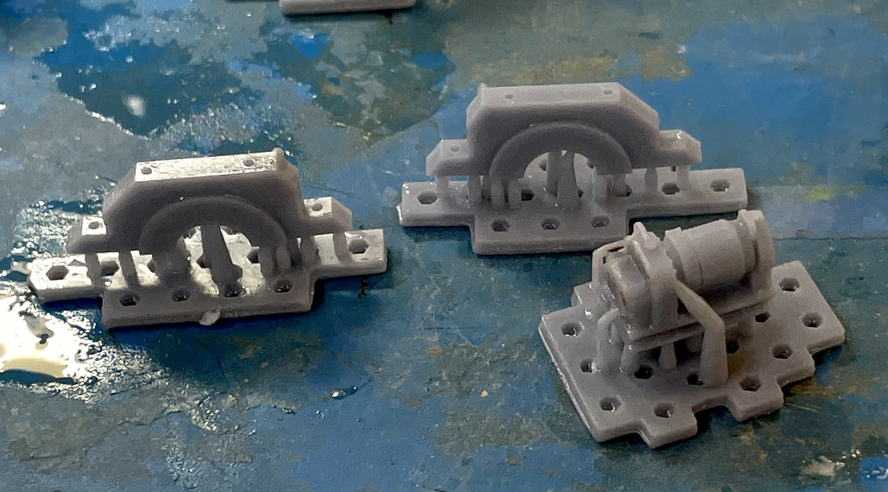
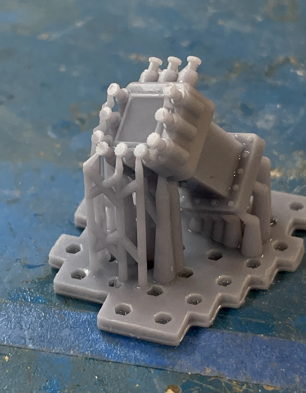
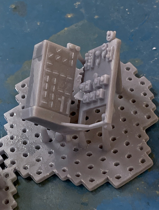
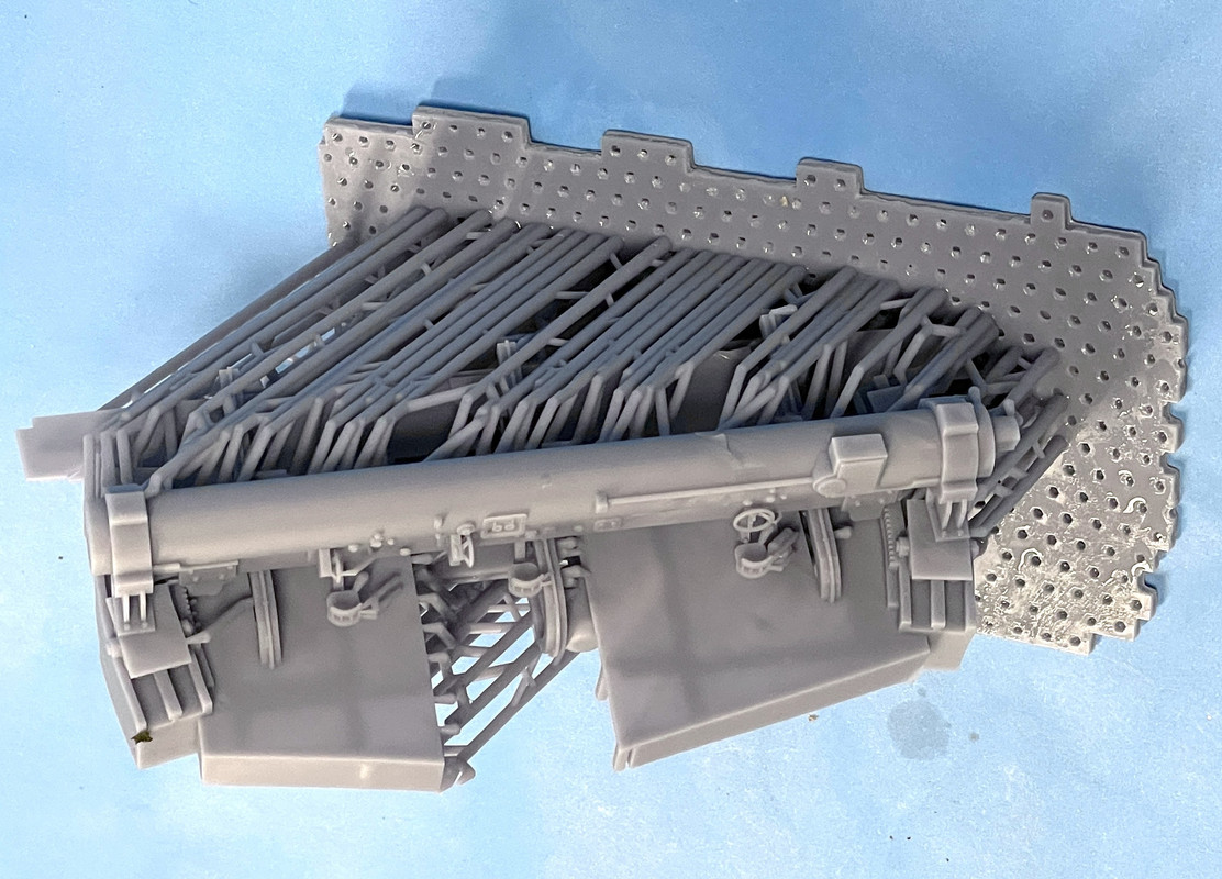
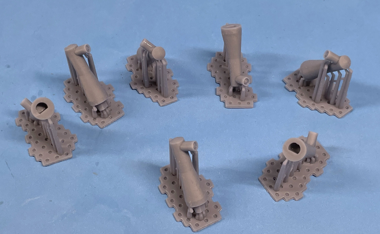
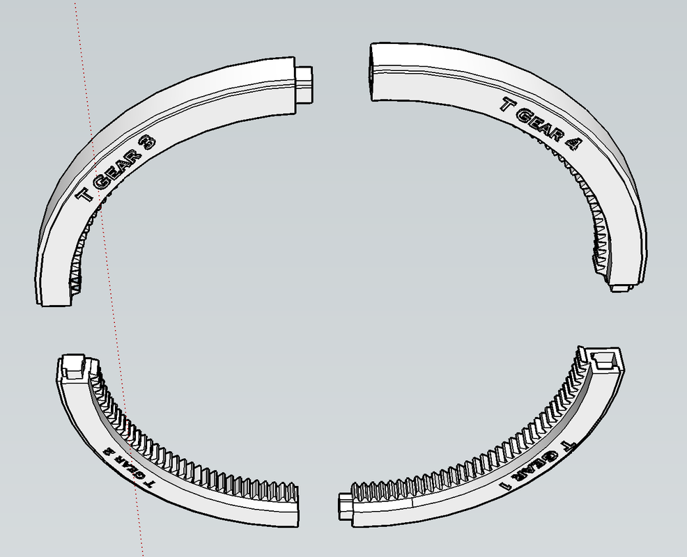
With the actual turning circle in hand, I was able to start finalizing critical parts for 3D printing. I can’t print the entire lower bearing race and traverse gear as a single part, or even a half, but I can print it in quarters. I devided it up and provided assembly keys so it goes back together properly. I’ve recently tried this technique on another long part and it works. I have a software add-in that lets me intersect one object with another an remove material with a mouse click. It worked well in creating the negative space for the keys to engage. This ring and race is a critical component of the finished model.

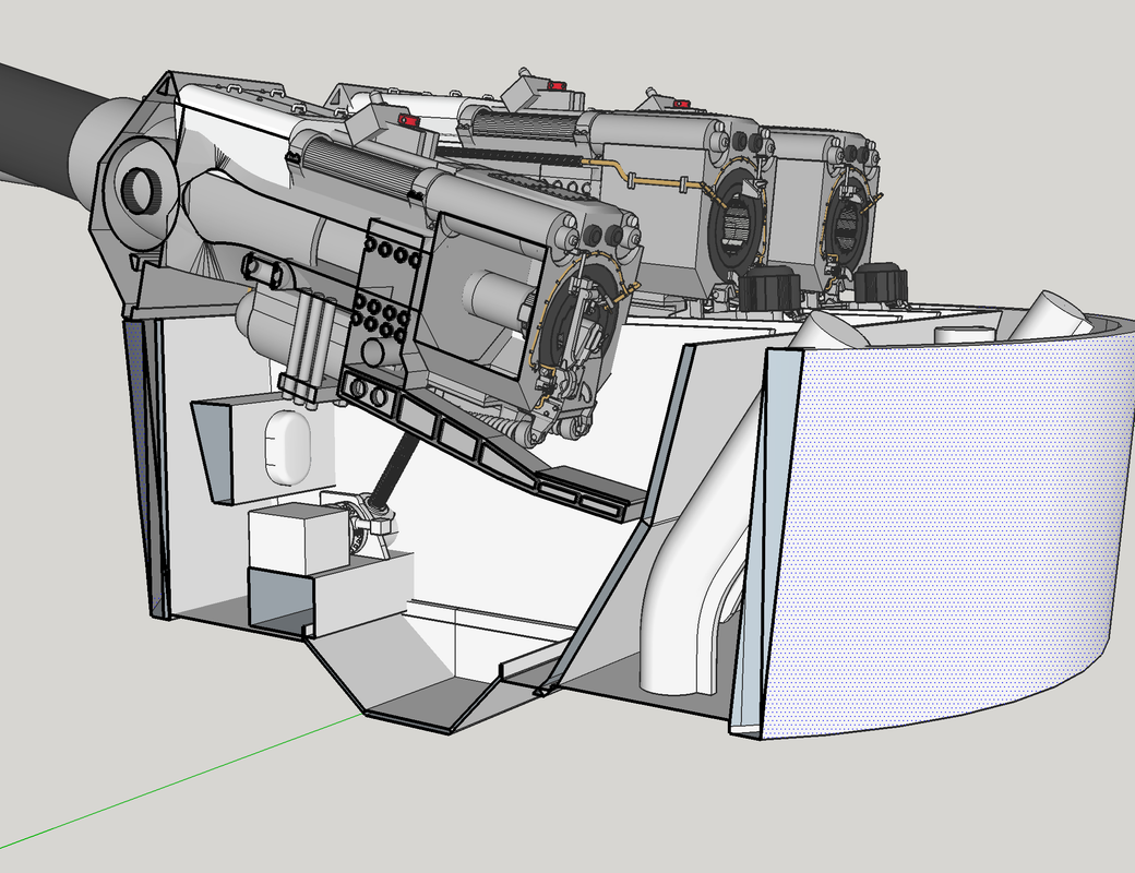
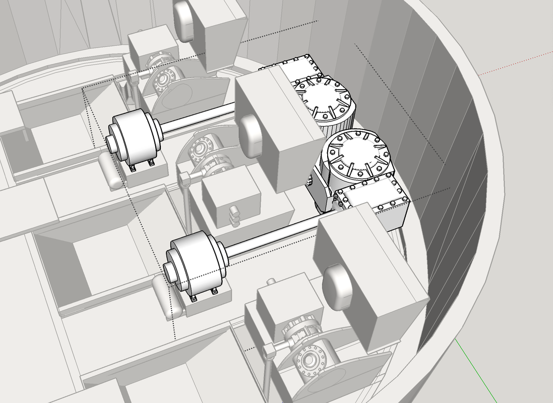
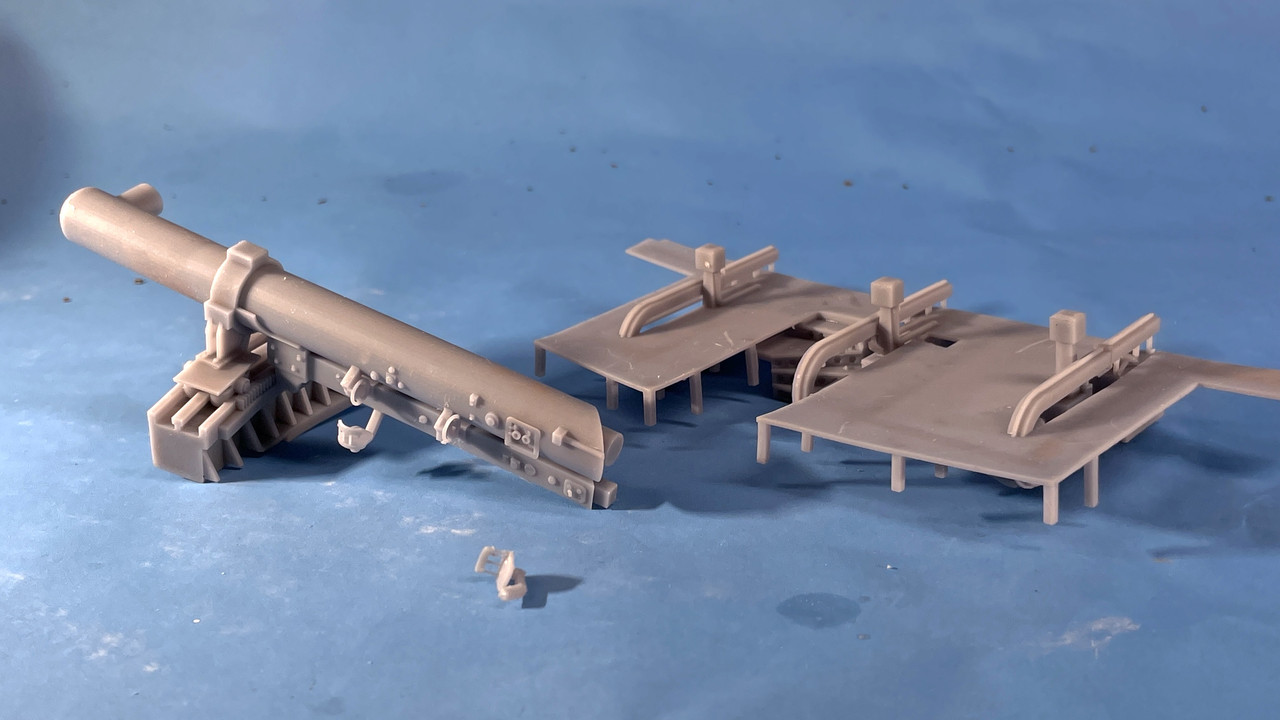
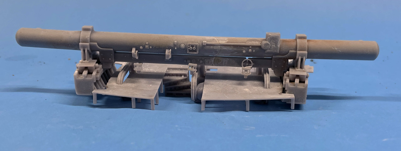
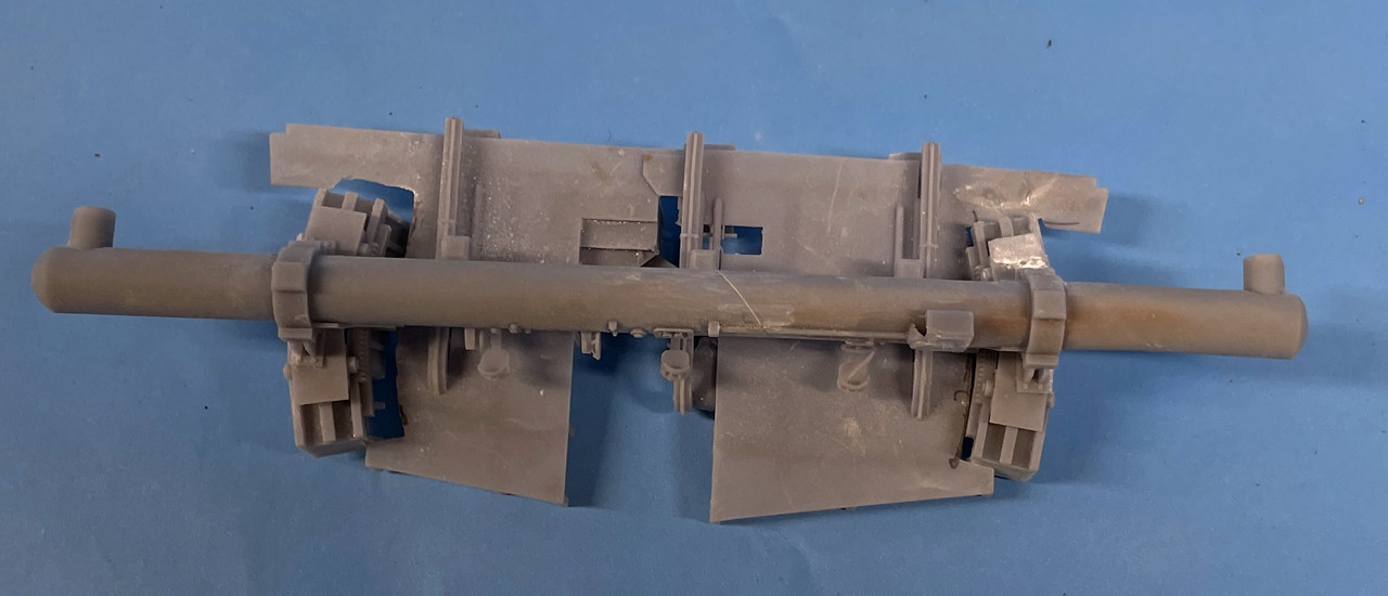
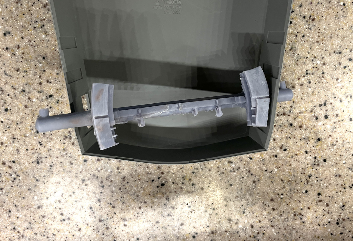
The gun bloomers from the kit are a two-part plastic affair. They come in an depressed and an elevated style. The kit guns glue directly into them. My guns theoretically will be movable, if I can make flexible bloomers. It’s one thing to make them look real, but quite another to make them look real and flex.

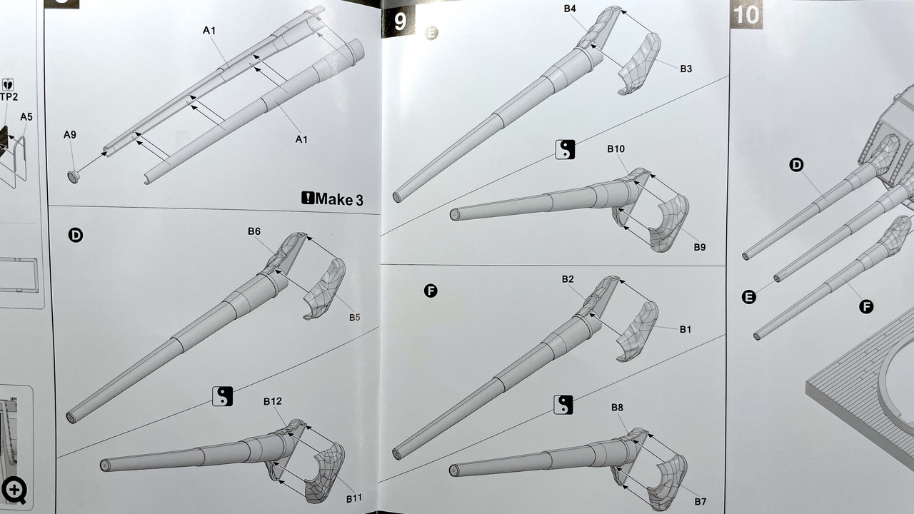
This is how the kit shows the guns going in. Obviously, with a fully detailed gun behind the bloomer, the kit method will not work.

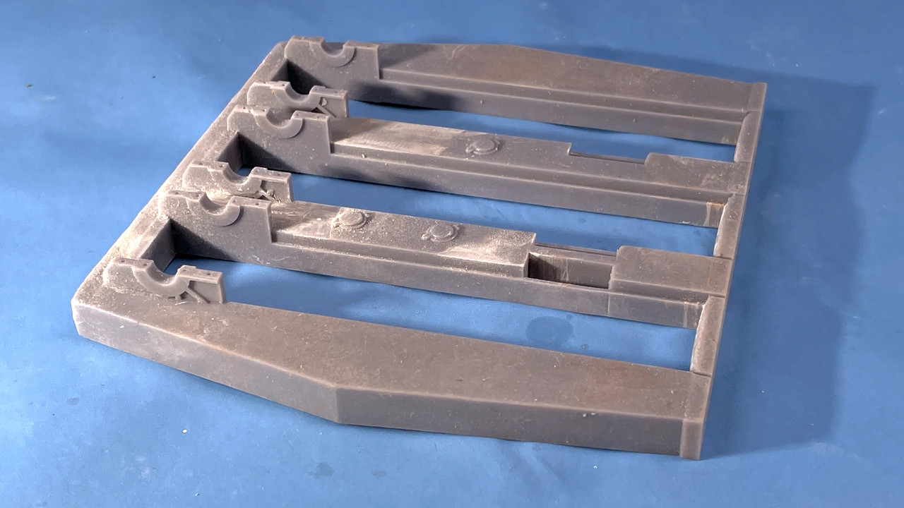
Here are the bloomer parts on the sprue.

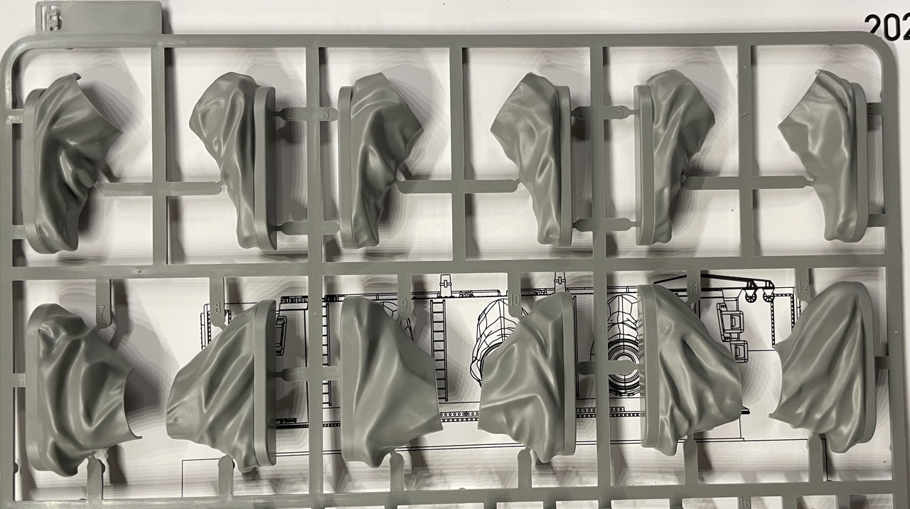
So I woke up this morning working out a method of making a flexible bloomer for this important model. My first thoughts were to coat the outside with silicone mold material in a few thin layers, but the color is wrong an nothing sticks to the silicone especially paint. Then I thought of using Liquid Electrical Tape which is a fluidized vinyl material that is already black and flexible. I thought again of assmbling the bloomer pairs and coating them with this material, but am concerned that the solvent in the liquid tape would not be compatible with the styene.

So I ended my mind experiment by using the silicone material to make a female mold of the assembled bloomer and pouring the liquid tape into the mold, pouring it out again so the material coats the interior, let it cure and do it a couple more times to build up the thickness. This would form a hollowed out perfect replica of the kit bloomer, but it should also flex depending how i can control the thickness. it will be an experiment.

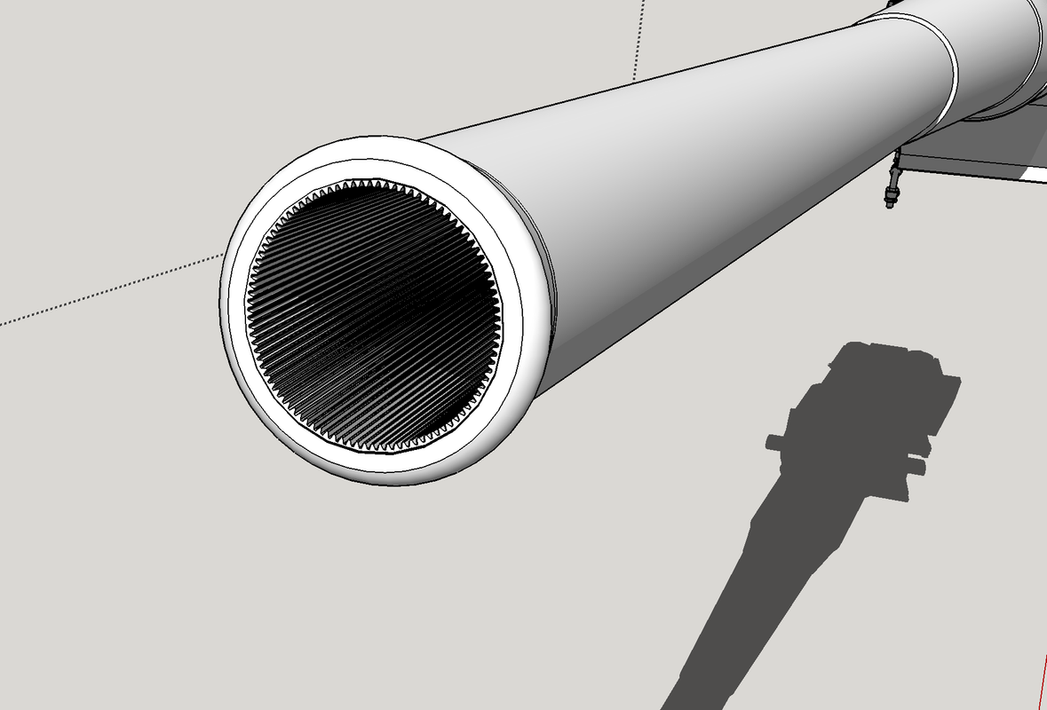
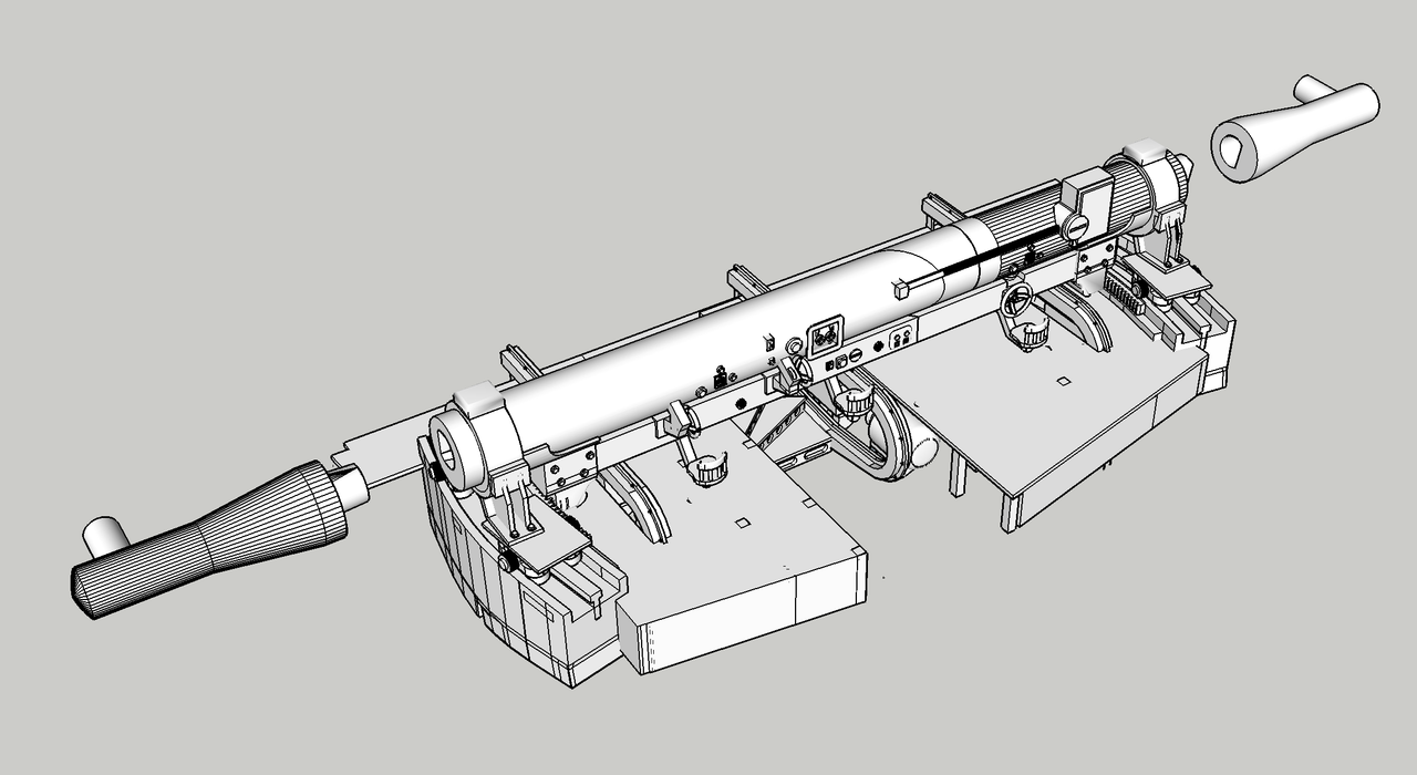
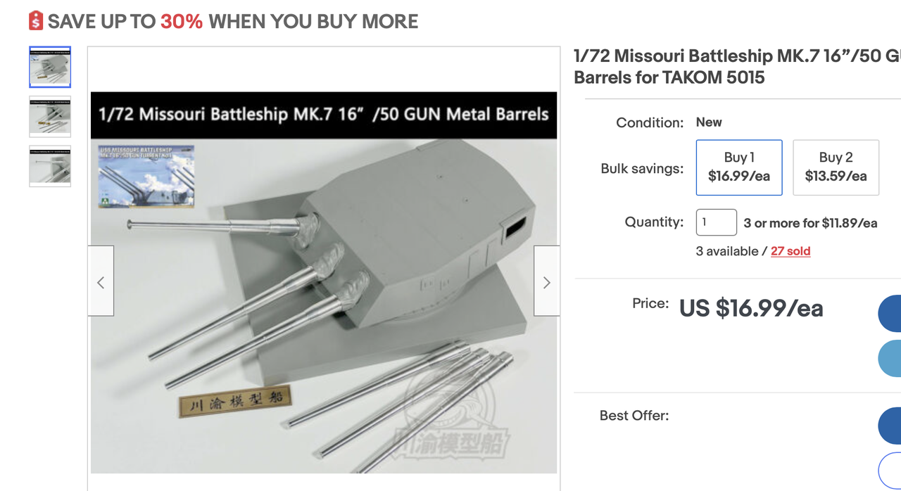
Lastly, I found the metal gun barrels on eBay, directed to me by one my blog readers, and ordered a set for me and two more for the hobby shop as requested by the owner. There was significant price break at three items. They’re coming from China with free shipping. The three-item price was $11.89. I really didn’t want to mess with the styrene guns. I did use the kit guns to refine the opening diameter in the slide assembly that I’ve drawn. The beauty of the metal barrels is already having a real metal finish on the exposed slide area. The guns are greased at that junction and I will have to simulate this on the bright aluminum.

The more I do on this project the more challenging it’s becoming. There are lots of variables to manage with many part interactions.

Exciting build so far for sure! Man your d sketchup skills are really growing strong. Can’t believe all you’ve done in it. It’s been years since i used sketchup but I remember it was pretty powerful for a free program and it appears to be really really good now given all you have done with it. hopefully i can see it in person sometime when itsdone!

I’ve messed around with it since Ver. 1.0 in the 90s, but never really started using it seriously until the last decade or so. Constantly learning new things to do with it, e.g., just learned how to make gears.

Working with my nephew on some custom work and paid me for my time with a new Elegoo Mars 3 printer. The 3 is 4X faster than my Mars “Classic”. It has about 30% more build volume with a slightly larger build area and more depth. It has a 4K monochromatic LCD in comparison to a 2k standard screen, so the horizontal resolution now is almost as good as the 10 micron vertical. I will use the old one for the thinner and less critical jobs.

It couldn’t have some at a better time as I’ve already put it into service printing critical parts for the turret project. The larger build space is already paying dividends printing the entire officer’s compartment floor plus the rammers attached in one piece. This greatly simplifies final assembly. I did a test print of the entire rear bulkhead, but it had a couple of errors (the drawing, not the machine) where the porthole lids delaminated from the surface. Cause? The two outer ones weren’t actually sitting on the surface. Printing doesn’t work on disconnected surfaces.

Here’s the set up for the entire officer’s compartment floor. I will print this on Monday. This would be a 20 hour print on my old machine, but now, at 2.5 seconds/layer, is about four hours.

I’ve also set up the ring gear segments for printing, two per load. I’ve fixed the bulkhead drawing and will reprint. I also set up all the rollers for printing. I woke up thinking about how to construct the working roller ring without going nuts.

I’m also laying out all the flat parts that will be fabricated out of sheet styrene. While I’m doing that I’m also thinking if any (all) qualify for laser cutting. I have access to the Makery at University of Louisville, but it has limited public open times and you need to reserve it ahead of time.

This will be a stunning display Piece when you have finished with the Build…Cheers Mark

Sure hope so…

With the new printer’s enhanced capabilities, I was able to get a perfect print of the entire officer’s compartment floor including the steps and all three ramming machines. This solved a huge assembly problem. In the prototype the floor panels are removable and wrap around the rammers. With the single print, I was able to simulate this. I’ve also included all elevating feet that hold it up.

Now all I have to do is remove that forrest of supports and post-cure it. Remember, prints just out of the machine are not fully cured. If they were, each layer couldn’t bond to the next. Some supports will be easier to remove in the soft state, others are better when hardened so the grinding burr works better. I’ve gotten pretty good at removing supports without damaging the part.

I also successfully printed and entire half of the rangefinder with all the attached things on it. It’s being cleaned now and the other half is in the printer. And I’ve designed the entire gun girder assembly includng the manual sighting stations and the powder hoist machinery as a single part. This JUST fits into my machine. It’s not the ideal angle for printing and may not be successful since it’s worth a try.

Here’s the drawing,

And here’s how it’s going to work in the printer. This is the slicer image. Remember; it prints upside down. I hollowed out the underside of the girders to reduce the amount of resin used, and the amount of resin in contact with the teflon seal.

The pink areas are parts of the base that extend past the machine’s limits. That doesn’t matter as long as none of the actual part are that color. I had to keep rotating in three axes to get it so it would all fit.

Here are the two parts of the rangefinder as they were on the printer. The detail is fabuloous. That gear rack is perfectly formed. This is the one that already printed. It’s the longer of the two parts and since it was so perfect, I’m sure the shorter one will be too. You can see the assembly keys that will ensure that the two parts mate correctly.

And the shorter part: Note that the seats and handwheels are all there. They’re going to be very delicate.

I downloaded dozens of new images from the Naval 16" 50 Cal turret operators manual, including things like these that I used to draw the manual sighting station equipement.

And this one that shows the cable hoist for the powder hoist system.

None of these images have any scale attached to them, so I have to constantly wing it, but the main thing is to ensure that it fits into the space allotted. I based the manual sighting stations on the spacing as they appear coming out of the turret sides. I may be wrong and if so would trim them off and just reprint the equipment, not the entire gun girder part.

My tour of the USS NJ is schedule for May 12. I will have a lot done by then. If the gun girder print is successful, I may use this method for the pan deck, electric deck and projectile flat printed with all the equipment already in place. It will greatly reduce gluing challenges.

As I’ve many times before, with a good 3D printer, a graphics program like SketchUp, and some computer graphics skills, If I can draw it I can make it.

In studying the manual deeply, I am still blown away by the sophistication and complication of the electro-hydraulc systems used to make a turret of this size work. Add to that the quadruple redundancy in making it work. In addition to the firing triggers in the plotting rooms (Two of them). Each manual sighting station had a firing trigger on their handwheels so the gun could be fired even if all of the other systems were out of commission.

Update:

The floor printed pretty well. It will need a touch of massaging to fit the plastic turret’s floor, but it will work. The left half of the RF printed very well, although I broke off one of the crew seats in getting off the supports. Actually, I thought all the supports were disconnected and pulled off the bunch, pulling off the seat and its bracket since the supports were still attached to it. The right half of the RF failed halfway through when the supports broke. I inadvertantly used Light Supports instead of Heavy and they’re just not up to the job. I genearlly use Heavy all the time and then go back and edit them in areas where there are fragile components and use light or medium supports. I’ve redone the support set up and will reprint tomorrow. I will glue the broken seat back on and may reinforce with some fine wire. Bondic joins to UV resin like crazy since it’s basically the same material and therefore is welding.

I need to double check the spacing of the two pointer and trainer telescopes compared to the openings in the plastic turret shell. This needs to be done BEFORE I spend the time and resin to print that large gun girder piece.

On the SketchUp forum a reader suggested re-positioning the gun girder so it would be flat on the bottom reducing the massive amount of supports (and saving some resin). When I turned it this way, the manual sighting stations were out of range.

So I changed the scheme. I removed the sighting stations and hoists. The stations were wrong anyway. I meausred the spacing of the sight locations on the plastic turret and they were not correct. I re-drew them to match the spacing. I then added the gun lugs to the girders. I had to re-check everything. The lug bores were quite wrong, and not in line or spaced correctly. So I re-measured the guns’ trunions diameter and the the exact width from the thrust surfaces and modified the lugs to match. I then split the lugs (prototypically… I might add) to create a removable cap to allow the guns to be lowered into the lugs. With the lugs embedded in the girders (again like the real ones) I couldn’t get the guns in since nothing would move.

Here’s the new scheme. The only required supports are for the horizontal surfaces that would not form properly with the reinforcement.

Here’s the printing scheme for the equipment I removed from the gun girder assembly.

I re-printed successfully the back bulkhead and re-printing the failed short half of the rangefinder. That’s going to done in a half hour.

Printed the remainder of the gun house details (well almost…). Got the rangefinder assembled and test fit on the officer’s compartment flooring. I will have to make some adjustments and will reprint the floor. That’s the trouble of building everything by eye without actual dimensions. But hey, all I have to do is change the drawings and print again. Got the hoists, sighting systems, gun lug caps, turret computer and communications panels including the switch matrix.

I’m using ChiTuBox Pro for the first time. It has many more features than the basic (free) program. A one-year license came with the printer. It has a “REPAIR” feature that lets you fix errors in the STL file. I tried it out on one version and uncorrected on the other. The “repair” closed off areas that were supposed to be kept open. The arrows show this.

I’m not going to use the repair function very often.

Here’s the finished Rangefinder. The joint worked pretty well and enabled me to put the two halves together in pretty good registration. I had to trim the floor to get it into place. I will reprint the floor with the proper clearances.

And from the top;

The apparatus prints are excellent! Everything shows up.

Here’s the manual sighting station. Note that the handgrips on the hand wheels were reproduced.

The trunion caps and hoists also printed accurately.

The officer compartment computer station is especially rewarding since all the hand knobs clearly printed including the indentations around their perimeter. My method of supports is to use all heavy supports, then go back and delete those on small, fragile and/or areas at the top of the model where the stresses would be less. I then replaced these with precisely placed at the same locations. This works.

Lastly here’s the communication and switch panel. I produced these as a linked single part to make their installation easier. Of of this will look pretty good once painted.

The full gun girder part is printing now. It will be a 9 hour print in the new machine. In the old one, it would be over 30 hours and wouldn’t fit anyway. Y’all will see if it’s successful tomorrow.

Looking forward to it! Dang you’vebuilt some great detail into this. Will be well worth using some clear plexi to open it up and make everything visible.

Thanks! I will be using a combination of clear Plexi for flat surfaces and cutaways for the circular compartments. Still working in my head as to how and where to make the invisible visible.

My idea to print the entire gun girder with the gun trunion lugs as a singe piece was successful! I could not have achieved this had the new printer not arrived. it’s larger capacity and resolution are making all of this possible. My first thoughts were to build the girders out of assembled styrene pieces. I wasn’t looking forward to that since keeping the geometry tight would be challenging.

This was the massive print as it came off the machine. Notice, the only supports were to allow the horizontal surfaces to print.

It was almost too big for my cleaning system. I had to use a paint brush to wash off the resin with the IPA, and then do it two times in the ultrasonic cleaner, turning it end-for-end so the whole thing would get cleaned. Here it is with the supports removed and sanded. I do the sanding AFTER post-curing it in the UV chamber. That too has a size limitation. I have to keep all this in mind if I ever want to got further up in printer sizes. They’re getting much larger with the addition of the Elegoo Saturn and Jupiter lines. I thought ahead and made rabbets where the styrene partitions will sit. This will add addition gluing surface for these vertical and thin parts. I adjusted the height of the part to accomodate the 1/8" deep rabbet.

The trunion bores are perfectly in line. I recently came to the realization that making the guns able to elevate is moot. Only one gun will be able to move… the one with the cradle/span tray in the retracted firing position. The other two guns in the loading position will have their spanning trays protruding into their breaches. If you attempt to move the gun you will break the cradle assembly.

Here are all the small parts going into the turret gun house. They are sitting in the UV curing box waiting to be hardened. I was rewarded when trial fitting the manual sighting equipment into the gun house plastic part that it fit perfectly. The tiny crew seats were very delicate and I broke of two. One I glued back with Bondic. The other disappeared and I’m re-creating it with Bondic also.

Then I ran into another challenge. The full-length rangefinder can’t be installed into the gun house part! To install it so it protrudes out of both RF extensions I would have to cut the gun house to open the existing holes to the bottom edge.

There’s always another way, and the solution actually is better. I re-drew the entire assembly, fixing all the probems I had with the flooring and the RF fit, and created as single part print. Then I split the RF just outside the supports on each end. These parts can now be installed from the outside AFTER the gun house is assembled.

I keyed the two extensions so there’s no chance to mix them up. The print, like the gun girders, is massive for my system and, also like the gun girder, just barely fit the cleaning stations. The print has lots of suppots! I noticed some stress cracking due to some shrinkage, but they’re fixable with Bondic. There’s also some minor imperfections in the area where the previous RF tube joint was. With this method I am assured that the RF is perfectly in line X-Y and Z directions and solves another assembly challenge.

Here are the RF optic tips after cleaning and before post-cure. I also fixed their geometry. They are taped. BTW: the RF/Floor is also in the raw state. Easier to remove supports when they’re slightly soft.

Just to be sure I just trial fit the new RF assembly into the turret gun house and it fits just fine.

Right now I’m finishing the drawings for the cradle-area sub-assembly of the gun compartment. There are still some gun house details that I’ve been overlooking. These include the ventilation system and all the electrical boxes and cabling that line the gun house walls. I’ve incorporated them into the rear bulkhead, but not the rear gun house wall. I don’t have a good image of the layout… just little snippets.

I’ve pretty much finished the pan floor detailing and will start printing that next week. That leaves the complex electric deck and the projectile flats. The powder handling spaces are not particularly interesting with some concentric spaces where powder bags are transferred from the magazine outside the barbette into the central rotation space where the powder hoists are.