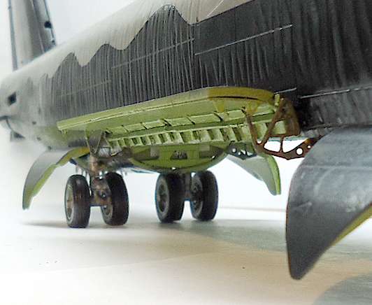
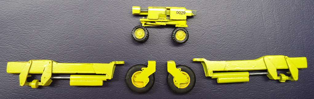
The previous wheel sets for the bomb lift trailer were just too big, even though they looked better. I replaced them with wheels from a Hasegawa US Aircraft Weapon Loading set. The scale is closer now to the actual unit.

The previous wheel sets for the bomb lift trailer were just too big, even though they looked better. I replaced them with wheels from a Hasegawa US Aircraft Weapon Loading set. The scale is closer now to the actual unit.
Hi Russ,
Great job on your build!
Ken
Hi, Ken. Thanks! [:)]
Inserted 6/4/19 from First Annual Berny Memorial Group Build, page 44.
The following is from some of my posts in Ken’s First Berny Memorial build, plus some supplemental information about building the bomb bay and cutting out the upper bomb bay doors.
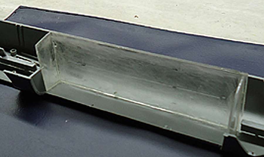
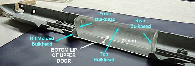
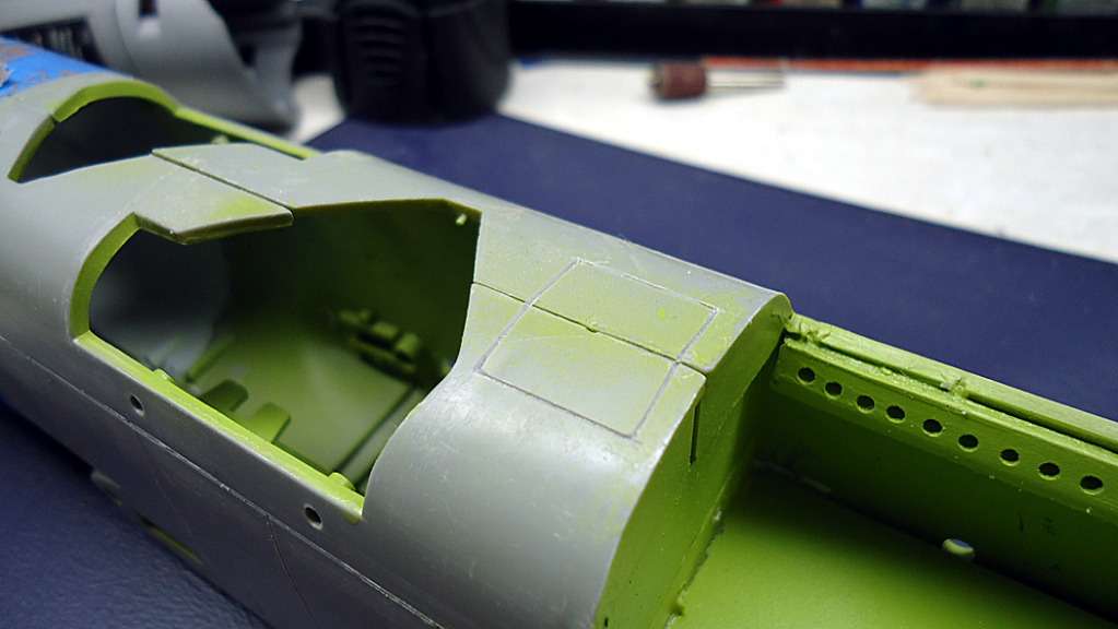
I built my bomb bay out of 1mm sheet plastic to fit into the right fuselage half, as shown below.
The dimensions for the internal structure are given in the diagram below. These dimensions are approximate and may need to be adjusted slightly for your installation. Test fit all parts before gluing the structure together. NOTE: You may have to trim some internal fuselage mounting points to fit the bulkheads.
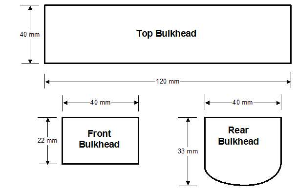
The kit comes with the lower curved part of the front bulkhead molded into the fuselage halves so you only need to add a top piece (Front Bulkhead in the image above) to complete the front bulkhead. Also, use this bottom bulkhead to shape the bottom of the Rear Bulkhead.
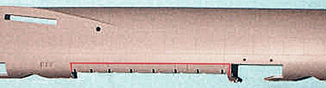
If you want to show the bomb bay doors opened to the load position, you will need to cut out the upper bomb bay doors. These are clearly outlined on the fuselage, as shown below. Use a sharp Xacto knife blade and cut carefully and repeatedly until the doors are separated.
Updated 8/4/19
Adding the Catwalks
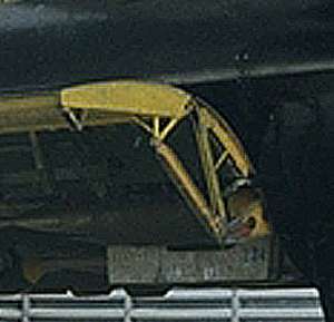
There were walkways (catwalks) on either side just above the lip of the bomb bay. These were part of a pathway that allowed you to crawl/crouch/stagger all the way from the cockpit to the tail gunner’s compartment.
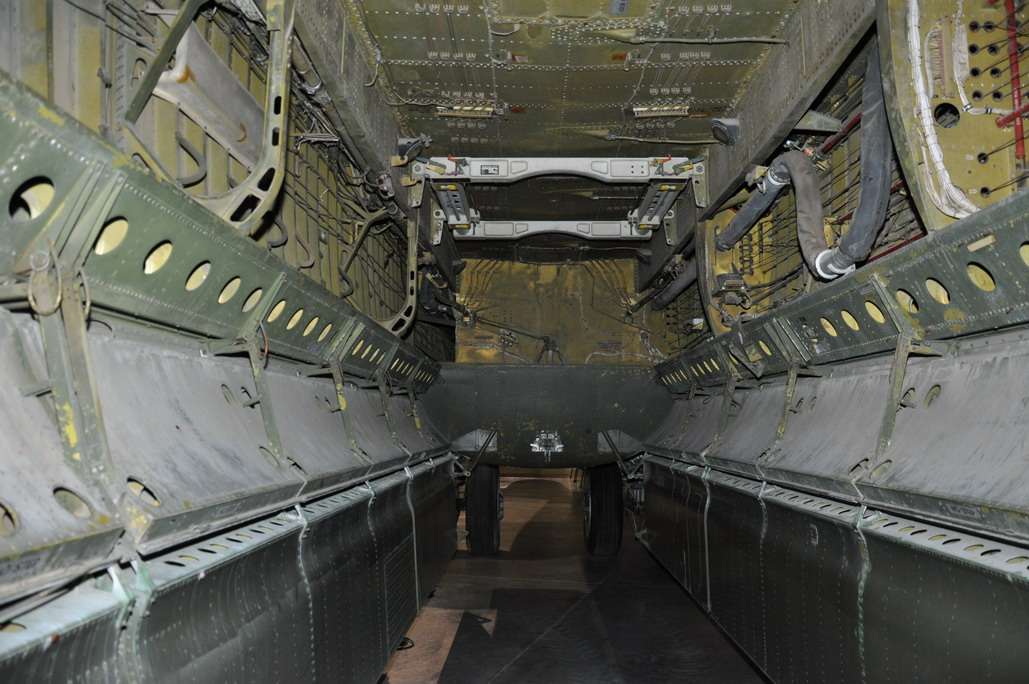
They definitely add interest to the model, so if you would like to add these, follow the procedure below.
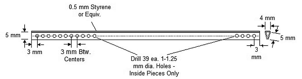
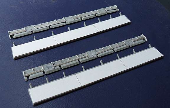
1.) Using 0.5 mm Styrene stock or equivalent, cut out four strips 120mm long by 5 mm wide, and two strips 120 mm long by 4 mm wide.
2.) Select two of the 120 x 5 mm strips and mark a line down the center of each.
3.) Starting from either end, mark off 39 points 3 mm apart along the center line.
4.) Using a 1-1.25 mm drill bit, drill 39 holes centered on the marked center line points.
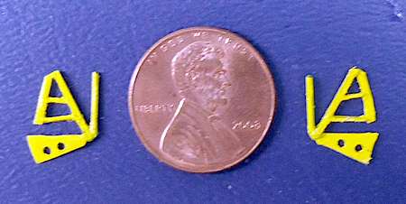
5.) Glue one 5 mm wide strip with holes and one 5 mm wide strip without holes to form a “V”, as shown in the diagram below.
6.) Glue a 4 mm wide strip along the open top of the “V”. This forms the catwalk “deck.”
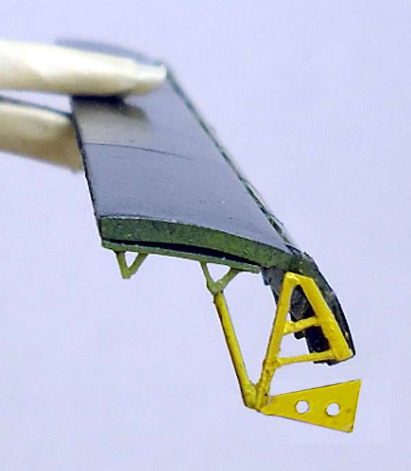
7.) Assemble the second catwalk per the above steps.
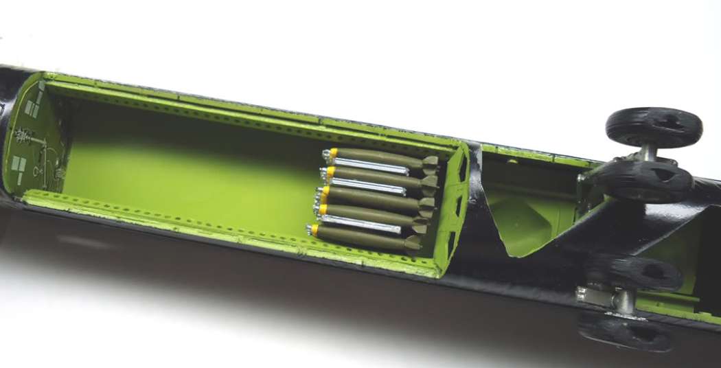
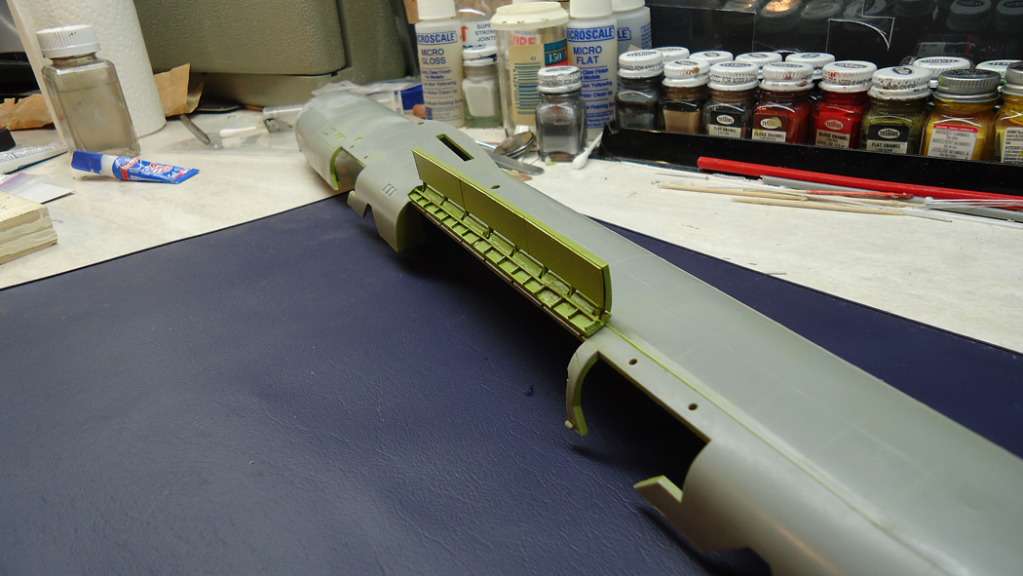
8.) Glue the catwalks to the inside lip of the bomb bay, as shown in the pictures below. NOTE: Be sure the sides with the holes faces inward.
Detailing and Attaching the Bomb Bay Doors
I added some card stock and styrene strip detail to the doors, as shown below. Note that this only “suggests” the actual detail; it’s not accurate.
Mounting the Doors
At this point, you’re faced with two choices for mounting the doors to the fuselage:
A) Glue the top edges of the upper doors directly to the fuselage, which is a messy way to do it and there’s no guarantee the doors will stay in place, or
B) provide some kind of attaching system that also supports the doors. The method I used is described below.
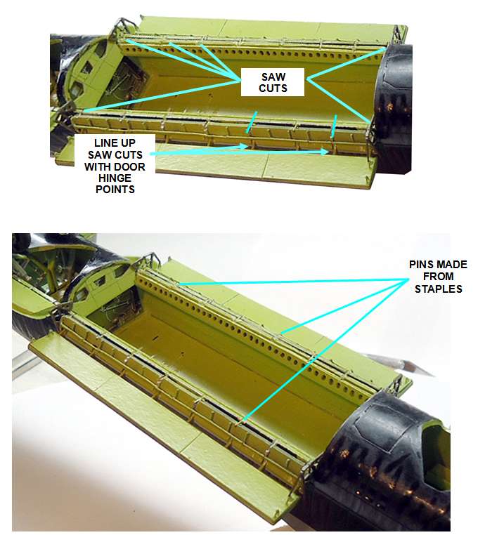
You will need some ordinary office staples for this task. Refer to the diagram below (NOTE: The photo shows my doors already assembled at this point, but mounting the upper doors to the fuselage first before attaching the lower doors will save you a lot of grief.)
There are 8 hinge points on the bottom edge of the upper door where the lower door hinges to it. Use these as a reference and with a razor saw, make shallow cuts about 1 mm deep across the top edge of each upper door, corresponding to the hinge points, as shown below.
Temporarily position each upper door in place and mark 8 points on the edge of the bomb bay corresponding to the saw cuts in the doors.
Make shallow saw cuts in the edges of the bomb bay at each mark.
Straighten and cut off lengths of staples to bridge across the slots in the bomb bay sides and the upper doors.
Position the first upper door so the top edge is even with the edge of the bomb bay and the slots line up.
Glue a piece of staple into each slot.
Attach the other upper door assembly in the same manner.
Once the upper doors are attached to the fuselage, attach each lower door to the upper door so that they are at a 90 degree angle to the upper door, as shown below. NOTE: I suggest you use rubber or tacky glue first to get the doors at the right angle before gluing them permanently.
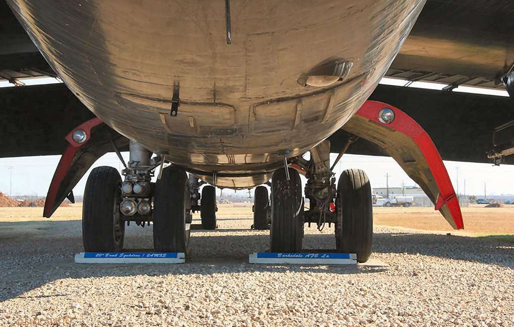
Here is the first set of bomb bay door safety locking assemblies. They’re a little bright in color right now but I’ll weather them when I do the fuselage.


Man this rocks! I’ll be watching this with great interest since I always wanted to do something similar but haven’t got the space!
Thanks, Duke, and welcome! Frankly, I don’t have the room either [:D]
Russ
The scribing is coming along (I spend more time repairing mistakes than scribing…). Below is a shot of the nose area. There is supposed to be a small antenna cover for the APX-26 IFF transponder just forward of the main hatch but the kit only represents this with a small blister of plastic. I ground it out and added a piece of shaped sprue. The area around the cover appears to be depressed slightly so that’s the way I modelled it.
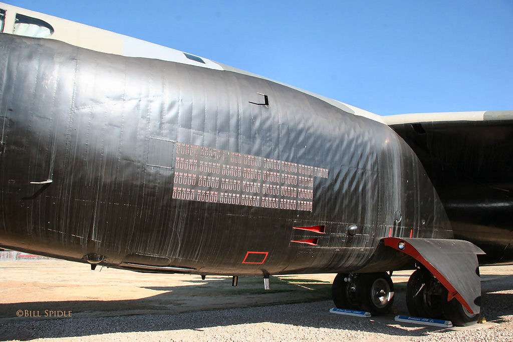
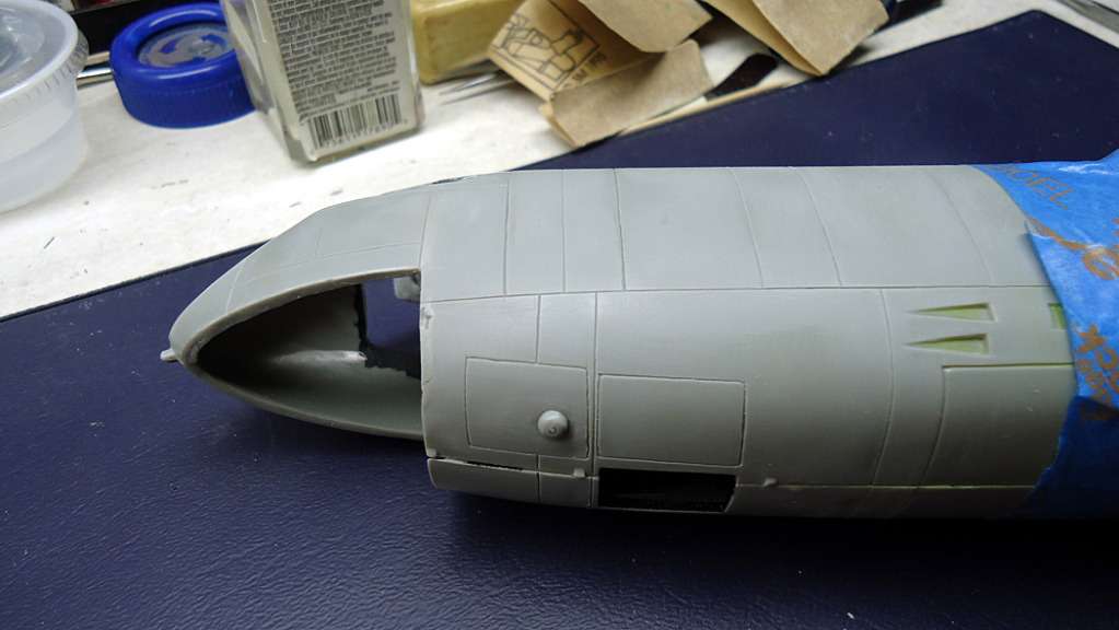


Also on top, the escape hatch for the EWO was outlined by two panel lines that looked more like the lines provided to indicate the walkway areas. I removed the inner line since the outer line is about the same size as the other hatches.

Also, the outline of the Doppler hight-finder radar antenna cover was left off. It should be between the bomb bay and the forward wheel wells, as shown below. NOTE: The fuselage halves are just taped together at this point.

Inserted 7/4/19 from First Annual Berny Memorial Group Build.
Here are the tools I use for scribing: a panel scriber and a dental pick (I filed the tips flat on this one to produce a sharp triangular shape). Both are available from Micro-Mark.
I used the panel scriber right over the top of the raised panel lines, then I used the dental pick to widen the lines and remove the debris created by the panel scriber.

Cheers,
Russ
Since I posted the above picture, I found two images (shown below) that indicate the “antenna” is actually the lens for the optical bombing sight with an offset cover housing. The first image shows the cover open and the second shows it closed Further, there is no recessed area around the base as it appeared to be in the first photo.
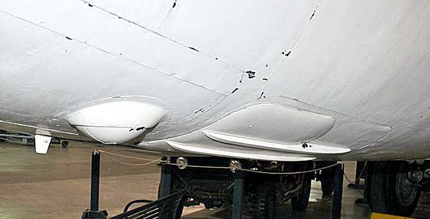
I plan to correct the model to show the offset cover housing but with the lens cover closed, as it would be with the aircraft on the ground.
Cheers,
Russ


Re scribeing an entire B-52. Now thats dedication. Great work Russ.
Thanks, Bish [:)] It’s a real challenge but I’m almost finished with the fuselage. The area aft of the rear main gear wells to the turret has been the hardest to resolve.
Russ
DX those armored trains and railway guns and you’ll have room for a BUFF [;)] [whstl]
Wow, I should check out the dio room more often. This build is looking great and is going to be epic. I will be following for sure.
Thanks for the good words, Jimmy and welcome [:D]. Scribing is slowing things down a bit but I hope to get back to building soon.
Russ
I already have room for a BUFF… on my ceiling where two of them are hanging! Besides, I can’t even display those trains and Dora anyway, so I’d still not have room on the table/shelves for a BUFF. Carlos, you really should come over sometime to see all 1100+ models in my hobby room. It has to be experienced personally; words just cannot capture the experience. [;)] [Y][H]
Keep those pics coming man, I’m really enjoying watching this come together!
Deal. I would love to see all your work in one place Mark. You gotta visit mine too sometime on another day that your work gets canceled and you make a trip to Brookhurst and I dont have to go running around after my dang kids…
I’ll be looking forward to it! Thanks Carlos!
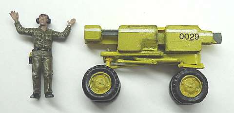
Well, I managed to break the point on my scriber so I did some work on the bomb lift trailer. The end and side units are pretty much done. Next will be the lift basket and arms.
Cheers,
Russ

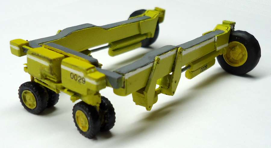
Here is the bomb lift trailer with the three units assembled. I’ll be adding the lift mechanism next.
Cheers,
Russ


Great work…really inspiring. This is going to be fun to watch. Slow project though…hope I make it long enough to see the end…and all three Hobbit movies…lol
Lol, thanks Prof. I hope I make it that long too [:)]