1/72 B-52D with Big Belly Mod, Operation Arc Light

Hi, All,

I finally found a photo that showed a combat-ready B-52D with fully loaded flare dispensers so I decided to try and model them. Unfortunately, I didn’t find a picture that gave me the exact placement for the dispensers so I had to make a best guess. The flare dispensers were mounted under the horizontal stabilizers as shown below.

Each B-52D had an AN/ALE-20 flare dispensing system that consisted of 6 flare dispensers, three on each side of the aircraft, and at least one control panel (I can’t remember if there were more) at the EWO station. There were also six rotating stepper switches (shaped like top hats), one for each dispenser, that were mounted under the horizontal stabilizers, three to a side. They were behind panels so they don’t show in the picture. The EWO control panel operated the stepper switches which fired the flare cartridges.

Each dispenser held 8 AN/ALA-17A flare cartridges and each cartridge held two flare pellets, for a total of 96 flares. A single flare dispenser is shown below with a flare cartridge cut in half just in front of it.

As ECM technicians in the Avionics Maintenance Squadron (AMS), we were responsible for ensuring that the dispensing system worked correctly. The Munitions Maintenance Squadron (MMS) folks were the only ones who loaded or handled the flare cartridges.

Cheers,

Russ

Very cool Russ! I really enjoy reading your descriptions and detailed information on the BUFF! Nice work on duplicating it on your model!

Ken

Dang Russ!

Wish I knew how you did that!

That detail not only looks great, it answers a lot of questions about where those units were placed.

No worries about the precise placement…“If it looks right, it is right”

The presentation of the individual units is very crisp, and looks embedded.

Another fantastic evolution Russ[:P]

Thanks for your pics and the flare unit shot, put away safely in my BUFF file.

Courtesy of:

http://www.militaryphotos.net/forums/showthread.php?172435-Military-Helicopters-amp-Planes-Flares/page3

Dom

Thanks for the good words, Ken! [:D].

Thanks for the good words, Dom! Actually, they are embedded, in a way. I cut out a shallow slot for each dispenser then glued short pieces of styrene rod in place. Once they were set, I trimmed off the rod even with the surface and painted them. They look a little ragged though because I made the slots a bit too wide.

Cool pictures of that Buff, BTW [D:]

Russ

If my memory hasn’t failed me. The flares look to be in the right spot. All my time was in G’s and H’s. Those have 6 dispensers under each stabilizer. There are some pretty decent pictures on pg 57 of the Walk Around B-52 Stratofortress book. THere is also a not so good picture of a D model taking off that shows the flare dispensers on pg 19 of B-52 Stratofortress in action.

Hi, Jim!

Thanks for that confirmation. I used three different photos but all were at pretty extreme angles so it was difficult to estimate where the row of dispensers began and ended. Also, thanks for the tip on the B-52 Stratofortress in Action book; I’ll check that out.

Russ

Those flares look like they are two stacked per ‘tube’. They look like magnesium bodies, and some kind of thermite flare mixture and ignition wires inside. That would make 16 individual flares per unit/pod. But I can’t be sure, unless I start looking them up. I can’t see the ‘ejection’ mechanism either, shotgun shells or some kind of blasting cap in the floor?

Dom

Dom,

Yes, there were two pellets per cartridge. I would think with one of those things igniting in that confined a space, the combustion gas alone would force it out at a pretty high rate of speed.

Russ

Hi, All,

Since I added the flare dispensers, I thought I would go ahead and build some D-21 chaff magazines for the chaff dispensers. I apologize if the following description gets a little long winded.

Updated 7/21/19.

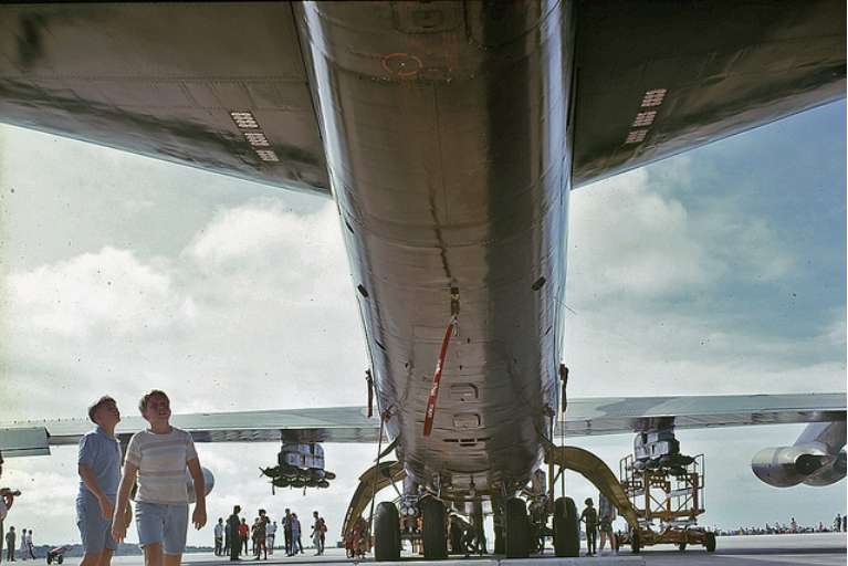
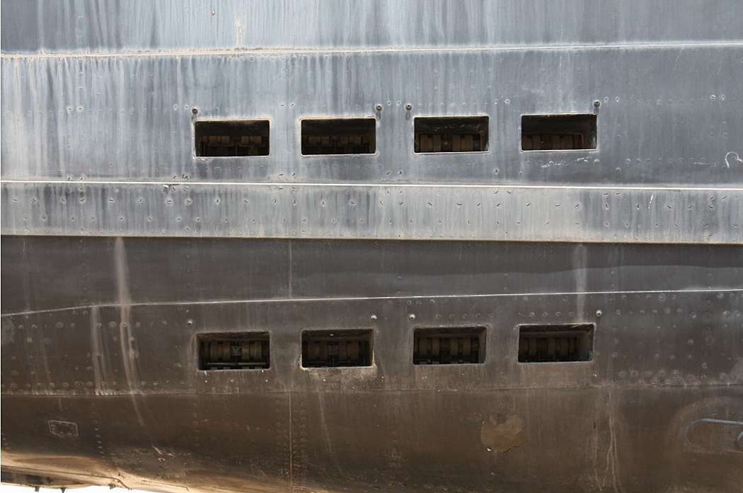
The chaff system on the B-52D was the AN/ALE-27 dispenser system, made by Lundy Corp. It consisted of 8 electrically-operated dispensers, 4 on each side of the 47-section in the tail of the airplane. There were 8 chaff ports on each side with 1 dispenser servicing 2 ports (chaff ports shown below).

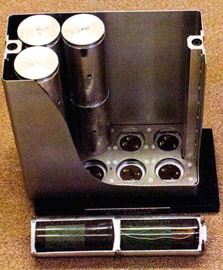
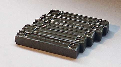
The picture below shows 4 chaff dispensers, each holding 2 D21 chaff magazines.

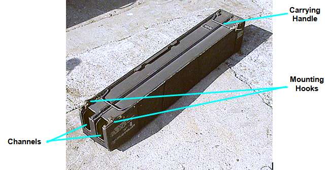
A single chaff magazine is shown in the photo below. There were 16 of these on each aircraft. The magazines were inserted into the dispensers using the two curved hooks at the bottom and rotated to a vertical position, then locked into place with clamps.

The chaff magazines were metal cases about 4 1/2 feet long and each magazine had two chaff channels. Each channel could hold a variety of different chaff bundles. These bundles were different thicknesses so the total number varied depending on the mission. Each magazine had two U-shaped handles that were used for carrying and mounting.

The magazines had spring-loaded “feeders” in each channel that were latched to the top during loading. After loading, the feeders were released. The feeders forced the chaff bundles down to the “gate” of each channel. The gate was a movable plate that held each bundle ready to be ejected. Each plate contained a cutter that ripped open the bundles as they were ejected. The plate could be adjusted for different sized bundles.

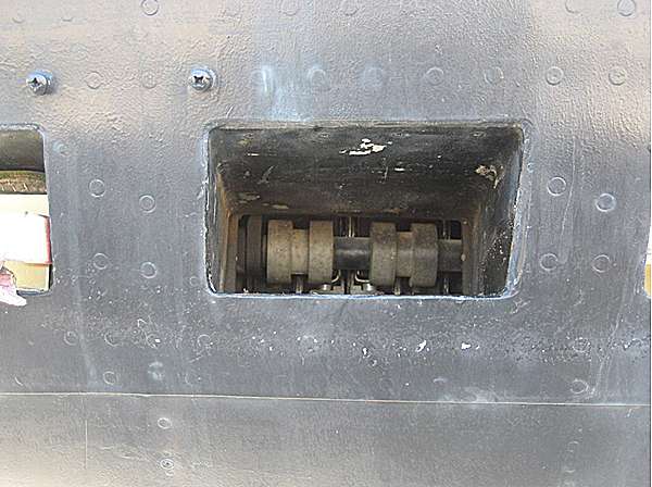
Each dispenser had an electric motor that drove four pawls mounted on a shaft, two for each chaff port, as shown below. The pawls had serrated edges that gripped the bundles and forced them out the chaff port. Each dispenser was programmed and activated by its own control panel at the EWO’s position.

One of the many jobs of the ECM tech was to load the chaff magazines prior to a mission. There were 16 chaff magazines per plane and they usually flew 4 planes in a cell, so there could be a lot of magazine loading to do depending on how much they were used.

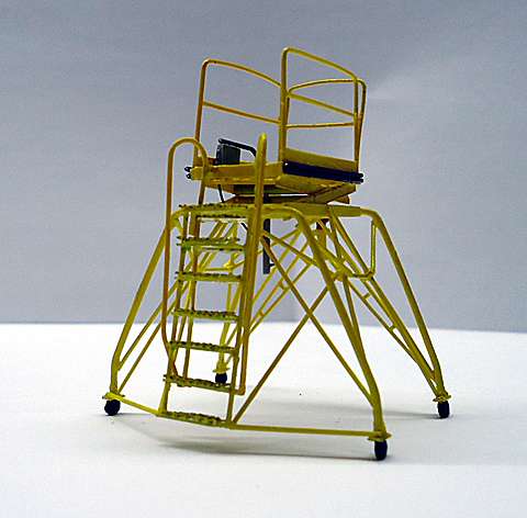
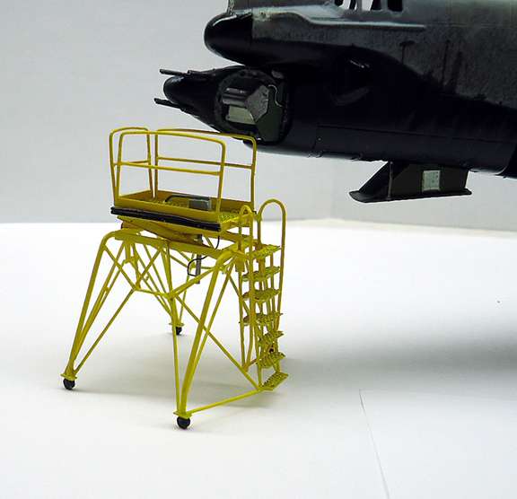
Once the magazines were loaded at the shop, they had to be carried out to the plane and manually heaved up into the 47 section. This usually involved two technicians. One tech on the ground passed a magazine to a tech on a B-4 stand under the 47-Section hatch and that tech would then heave the magazine up into the aircraft and onto a catwalk that ran through the 47 section.

Each magazine weighed about 40 lb fully loaded, so after heaving 8-16 of these, you were ready for a break. Fortunately, we didn’t have to load magazines for every mission since chaff wasn’t always used. But if any dispenser was used, its magazines had to be reloaded.

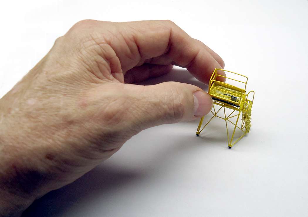
Below is a photo of some of the 8 magazines I made.

Cheers,

Russ

Hello!

Great info here! Isn’t it amazing, how much work goes into keeping such a weapons system operational? This modelling project is already very special, good luck finishing it, and have a nice day

Paweł

Hi Russ,

Once again I am spell bound reading your description of how all this worked. Thank you for taking the time to write it all down and share it with us!

Great job again on the detail! Looks just like your picture! [Y] [Y]

Ken

Hi, Pawel,

Thank you! And thanks for stopping by.

Russ

Thanks, Ken! Glad it didn’t put you to sleep [:D].

Russ

Hi, All,

I’ll be starting back up on the base for my diorama soon but in the meantime, I decided to complete my suite of maintenance stands by building a model of the B-5 stand. If I had known how difficult it would prove to be, I think I would have decided against it, but now that I’m finished, I’m glad I went ahead. Anyway, some pictures below.

BTW, if you’re interested in building one of these, PM me - I’ve written a manual for it.

Cheers,

Russ

Excellent work Russ,

you’ve really got the bending of those hand-rails down to a science.

That first photo, pardon me, reminds me of

War of The Worlds…

I’m glad you didn’t ‘chicken out’ of building that stand,

it was well worth it from where I sit!

That is a great looking suite of maintenance stands,

[Y][Y][Y][Y]

Dom

Lol, I see what you mean [:D] . Thanks for the good words, Dom!

Russ

The stuff you are making for this build really go beyond detailing, these are amazing.

In the second pic, whats that coming out of the bottom of the aircraft, i don’t recall that being on the kit.

Thanks, Bish. That’s the drag chute tray. It’s just an outline on the kit - I cut out the panel and scratchbuilt the tray.

I was thinking it might be something to do with the guns, maybe for spent cases. Thats another nice piece of detailing.