1/6th scale Scratch built Initial Tiger I Project

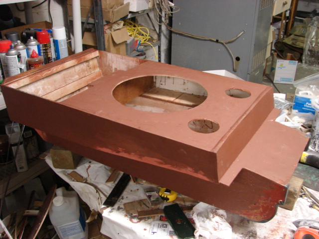
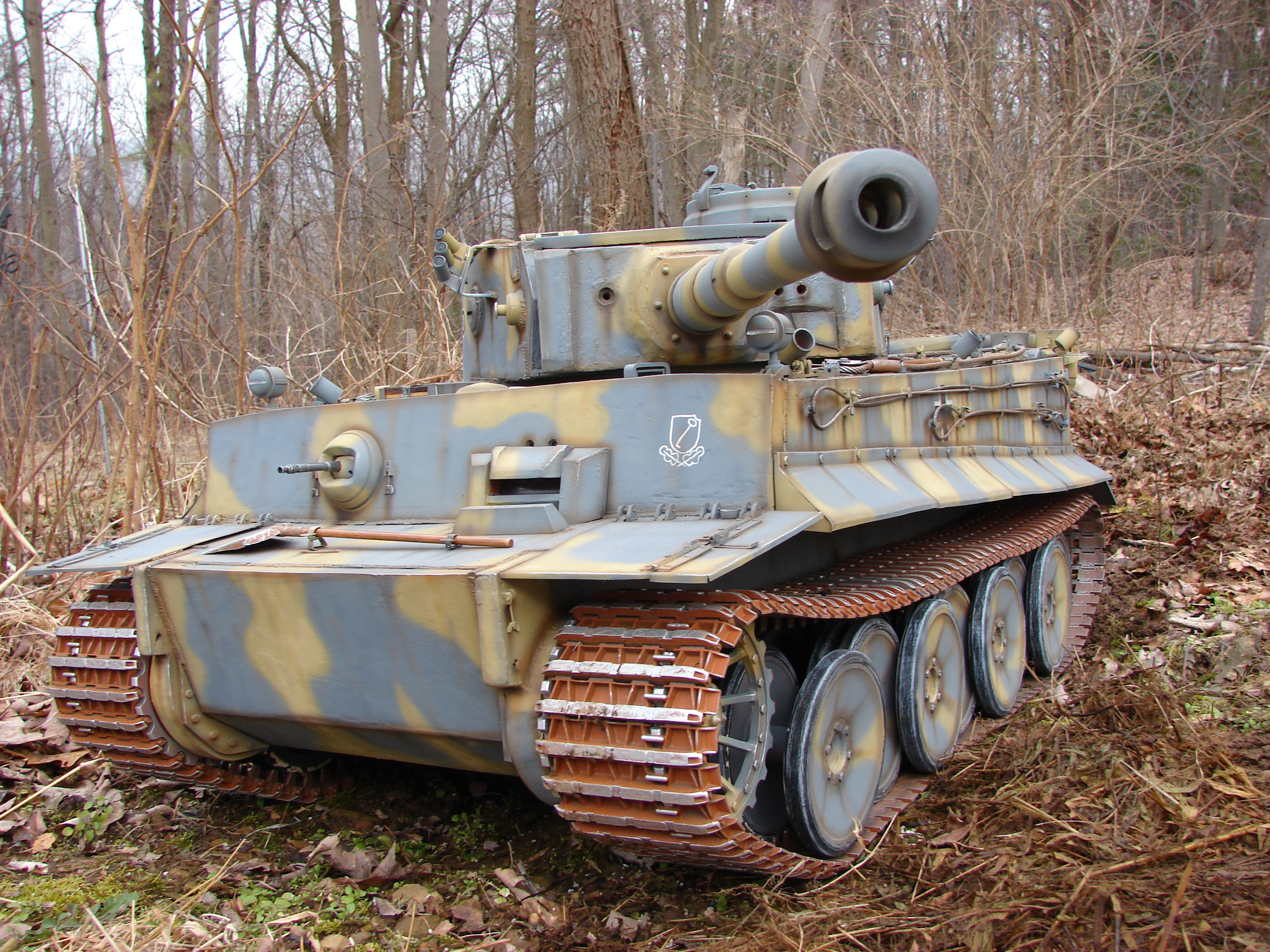
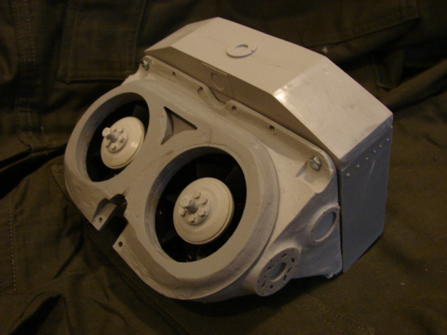
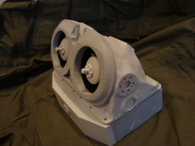
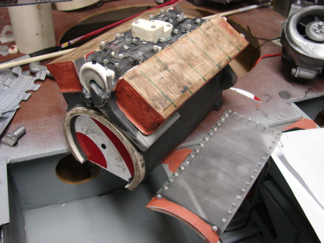
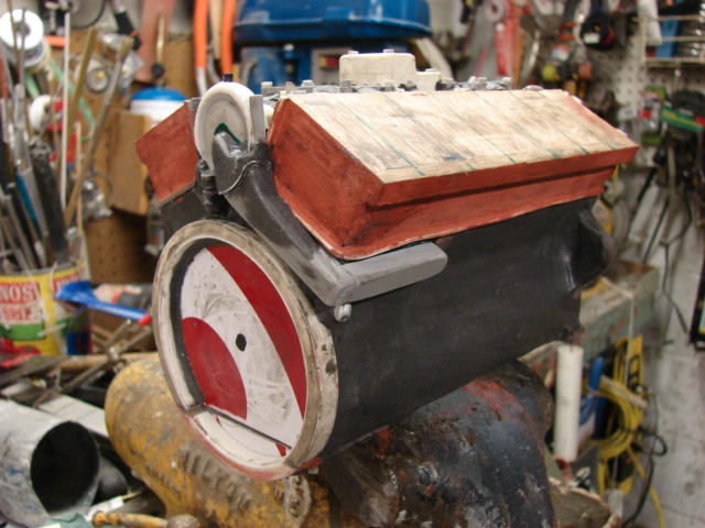
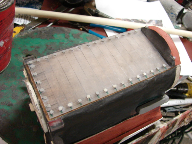
Hi Guys, With the M4A3 105 out of the way I have started on my next project which will be an early initial production Tiger I. For the build I have dug out this old partially started Tiger I.

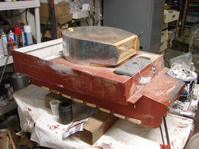
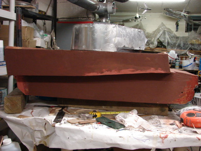
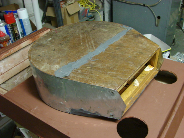
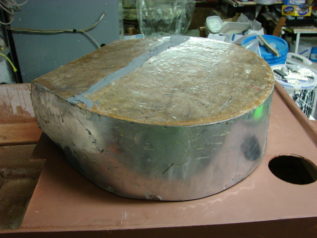
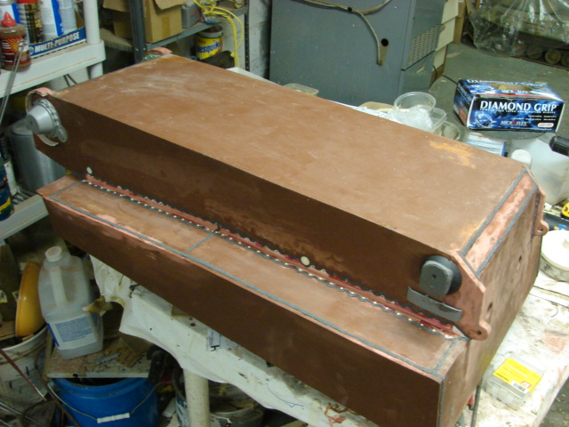
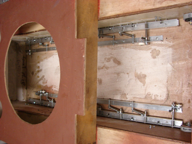
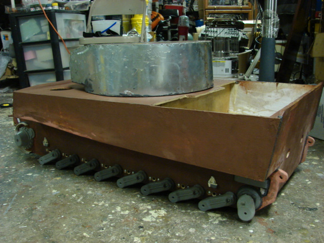
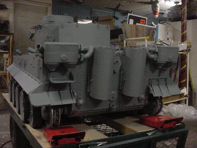
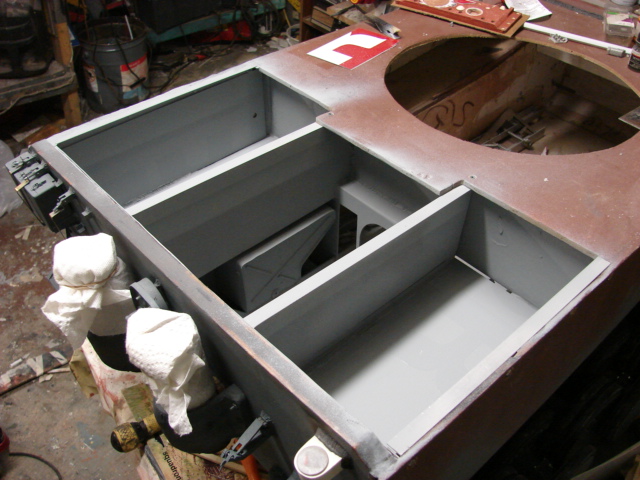
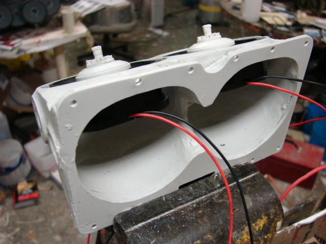
The tank hull is all constructed out of 1/4 inch thick plywood. and the turret is constructed out of layers of plywood and sheet metal. The tank’s hull and turret was started back in 2001, but never progressed passed the rough shape point that you see below and has been in storage ever since.

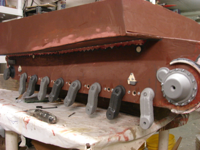
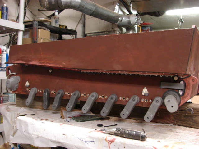
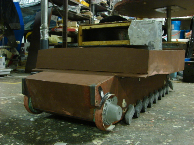
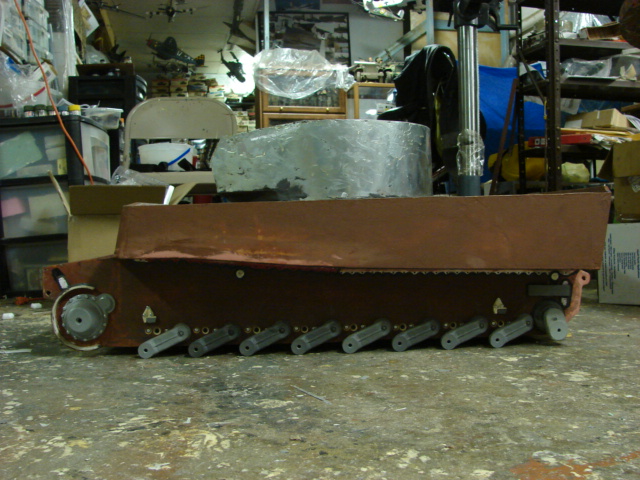
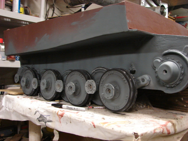
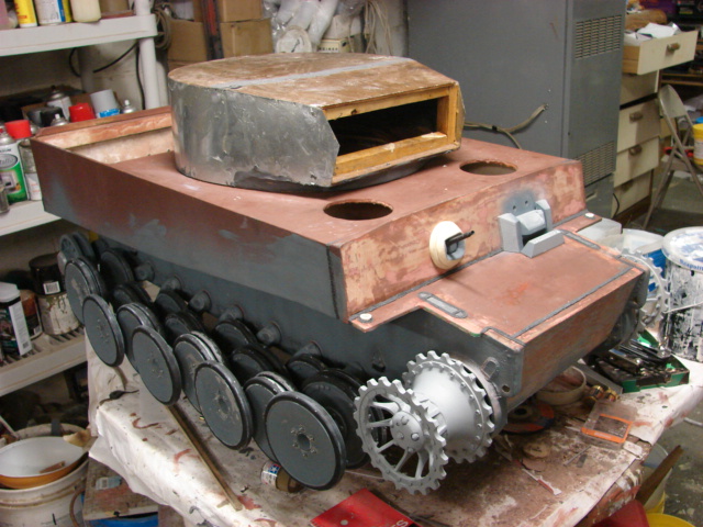
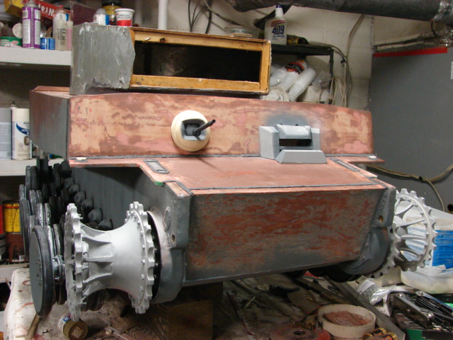
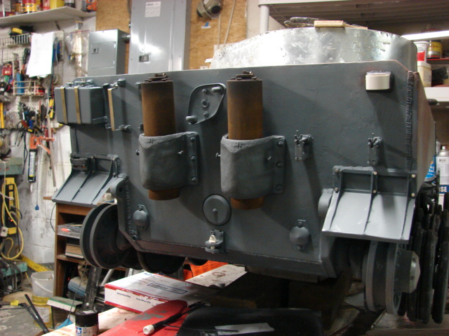
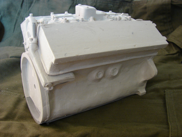
After about a week and a half of tweaking, altering, and refining the tank’s hull and turret is now ready for build up.

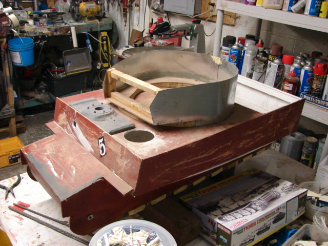
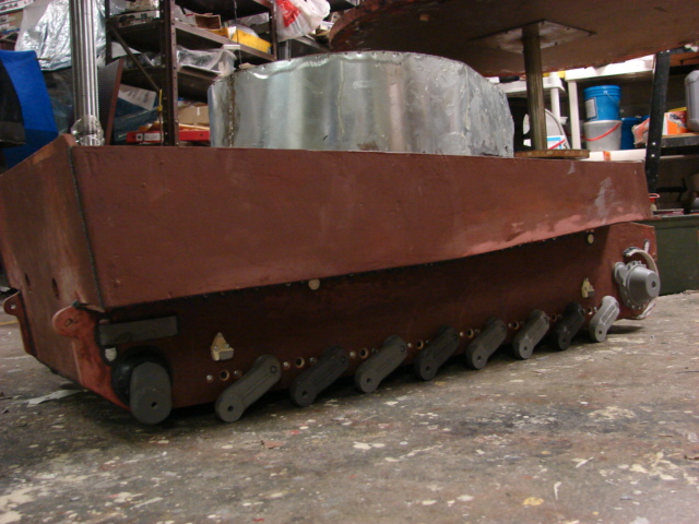
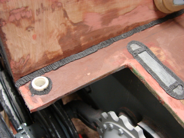
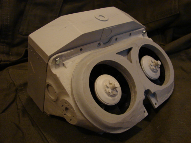
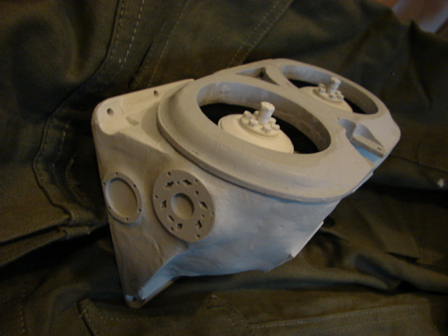
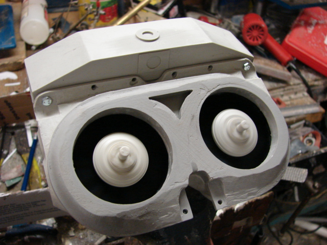
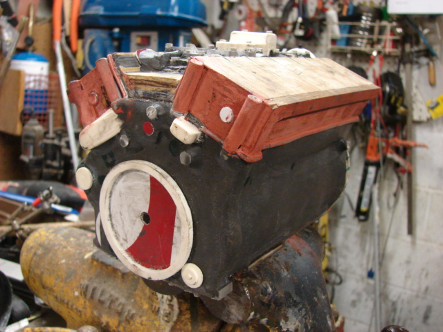
All of the tank’s wooden panels were thoroughly coated in Fiberglass resin and sanded to a smooth finish. As I mentioned in my past builds the fiberglass resin coating makes the model stronger, weatherproof, and transforms the wooden surface into plastic by removing wood grain.

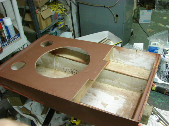
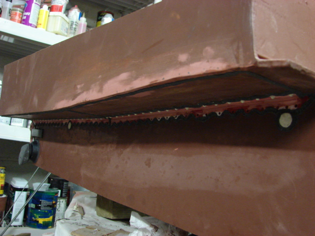
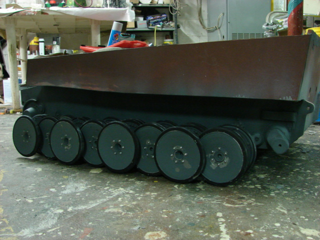
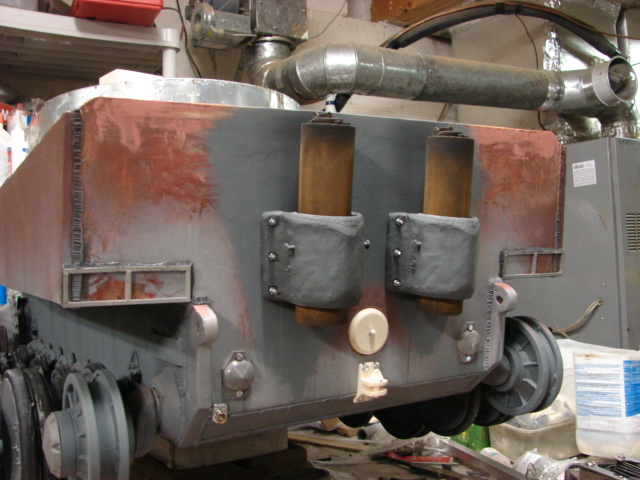
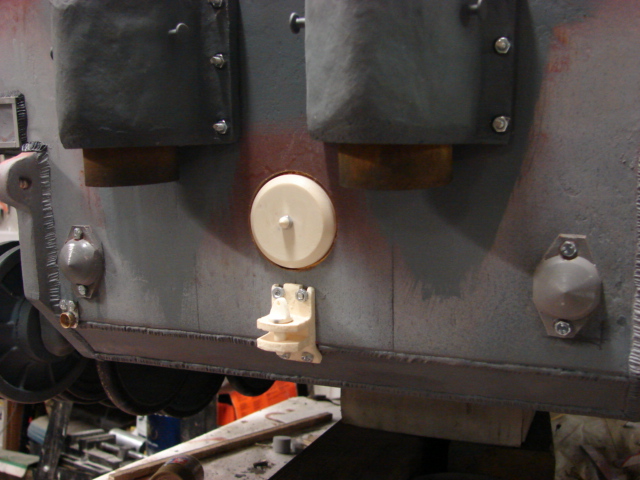
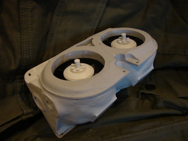
On the original hull the upper and lower hull were designed to be two separate pieces, during the refinement the these two halves were mounted together creating one unit.

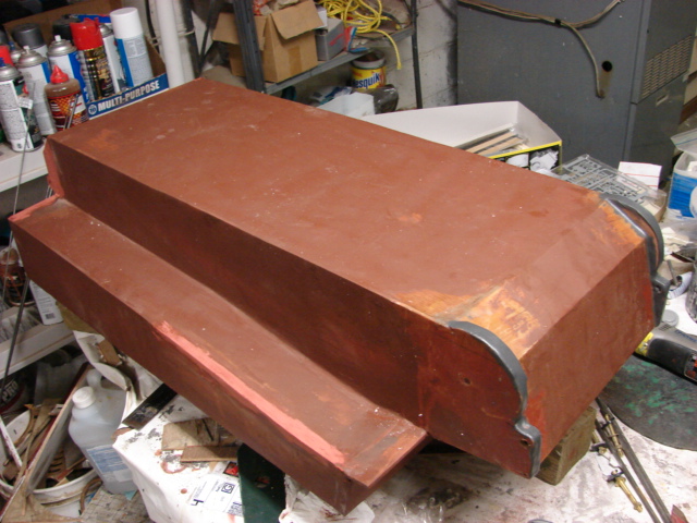
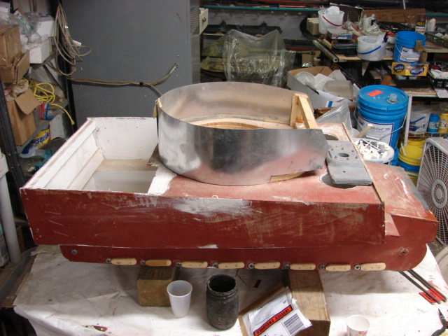
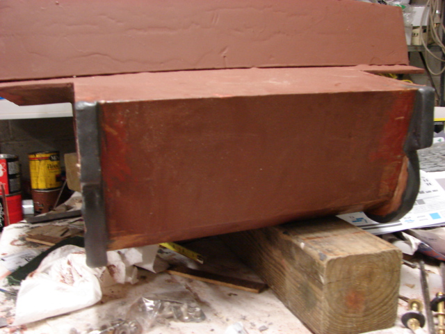
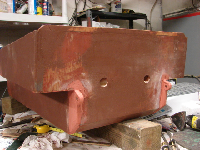
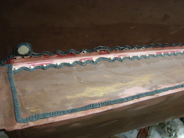
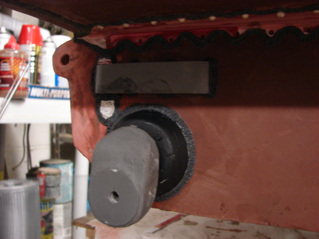
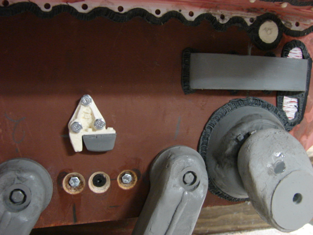
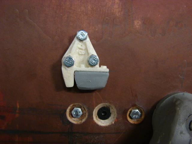
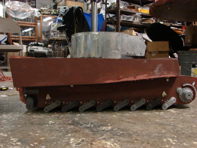
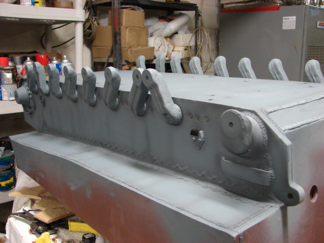
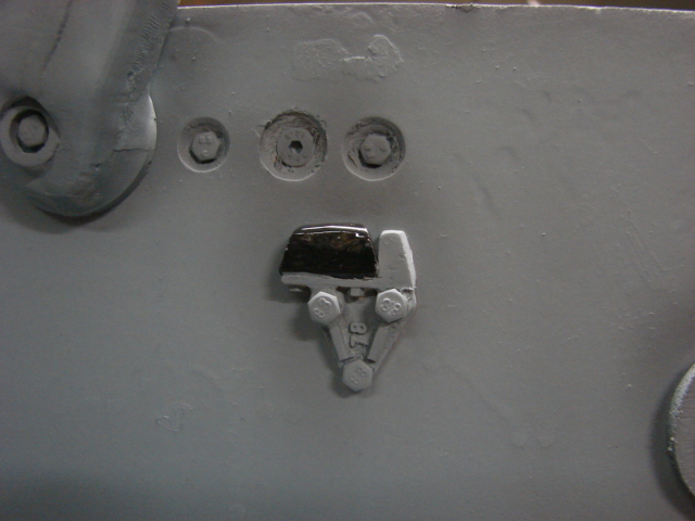
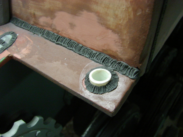
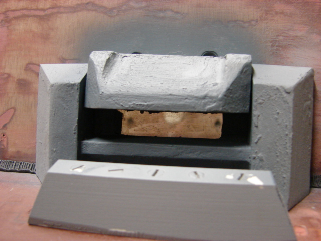
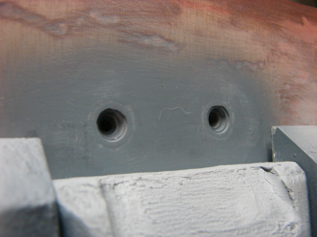
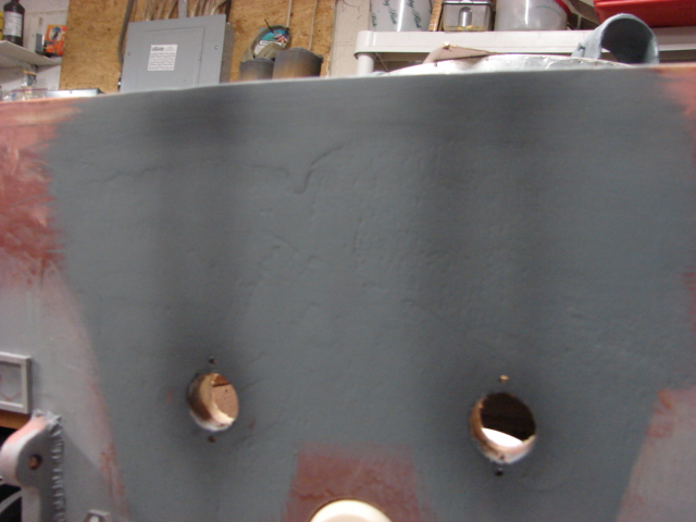
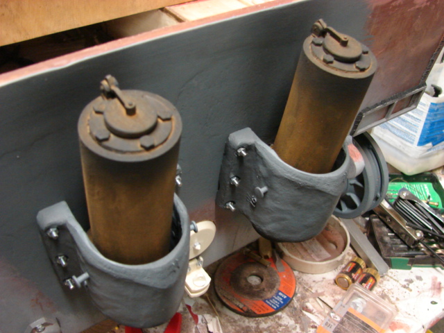
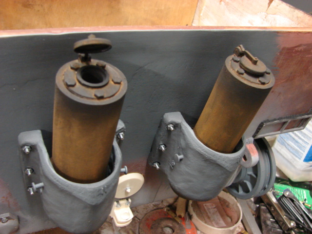
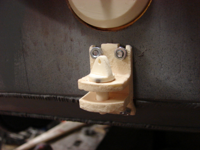
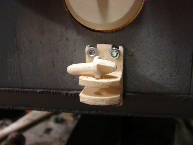
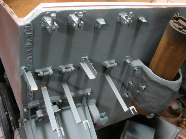
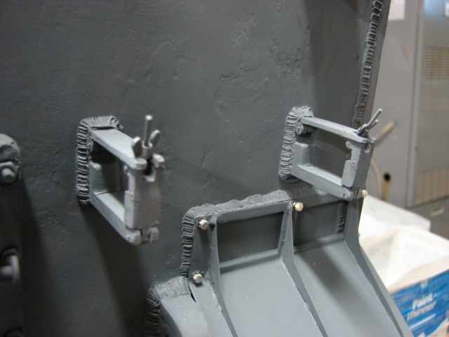
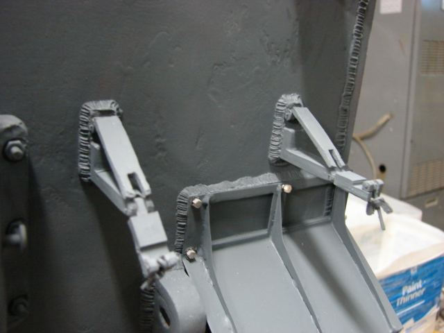
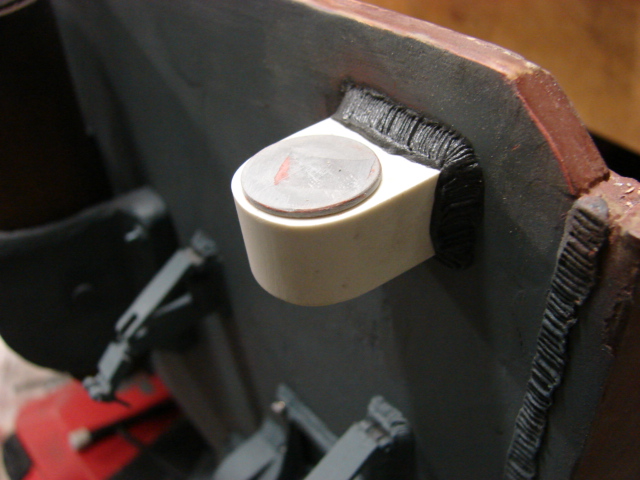
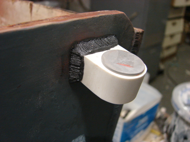
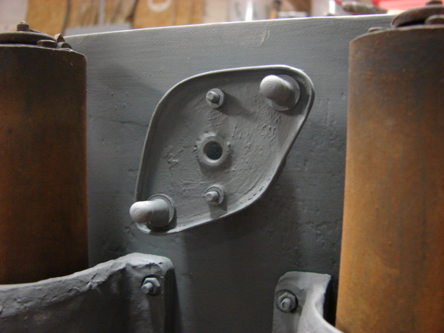
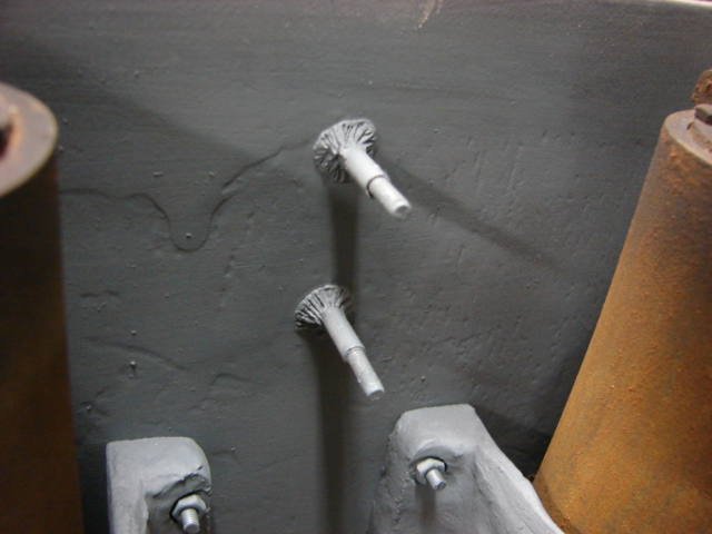
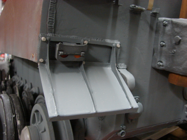
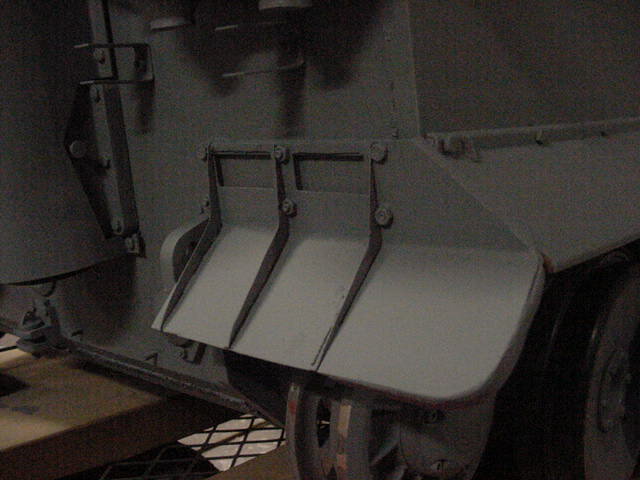
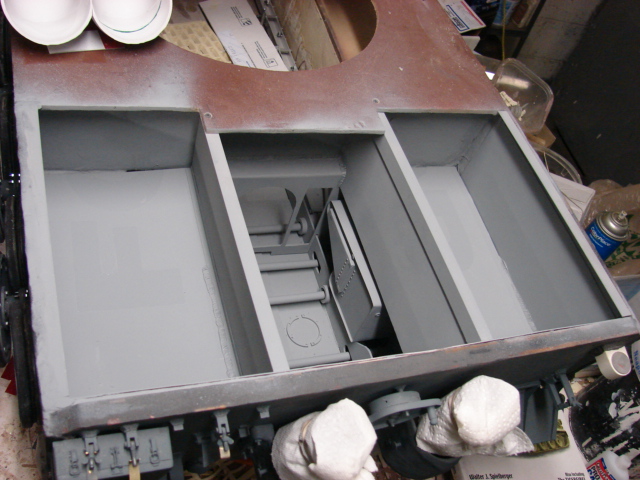
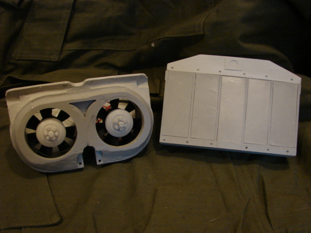
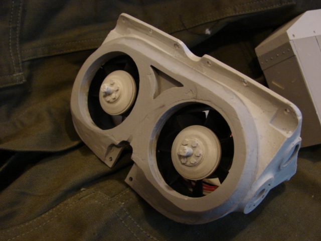
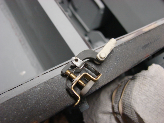
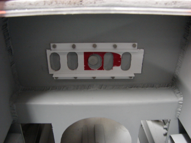
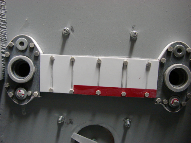
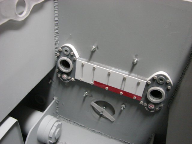
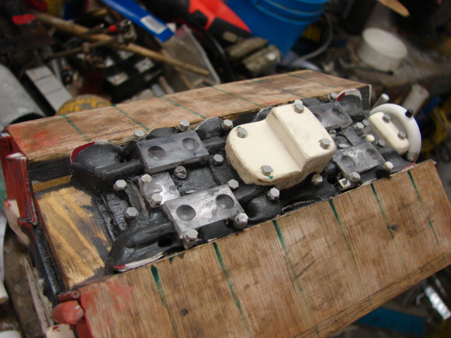
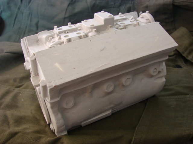
The lower hull tow shackle mounts were added. The final drive guard strip will be next.

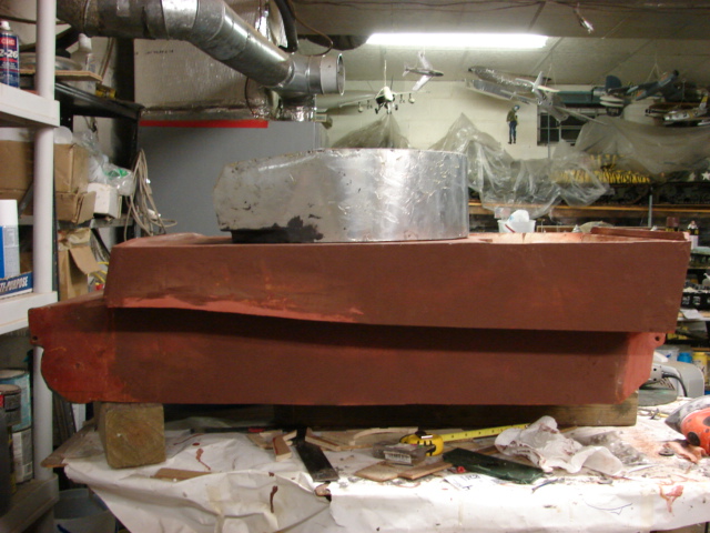
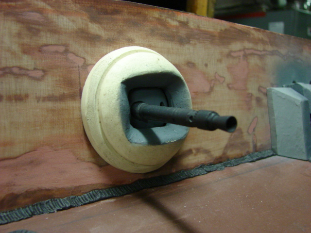
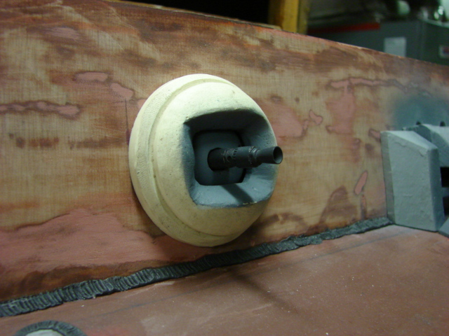
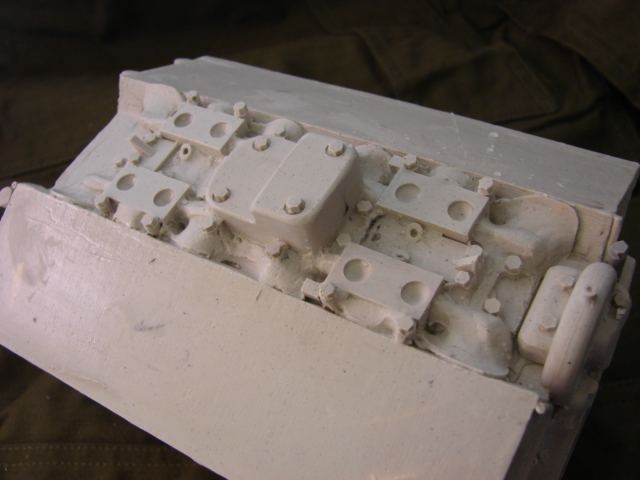
On the tank’s turret The roof was added. More progress will be added to the turret as the build progresses.

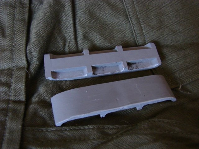
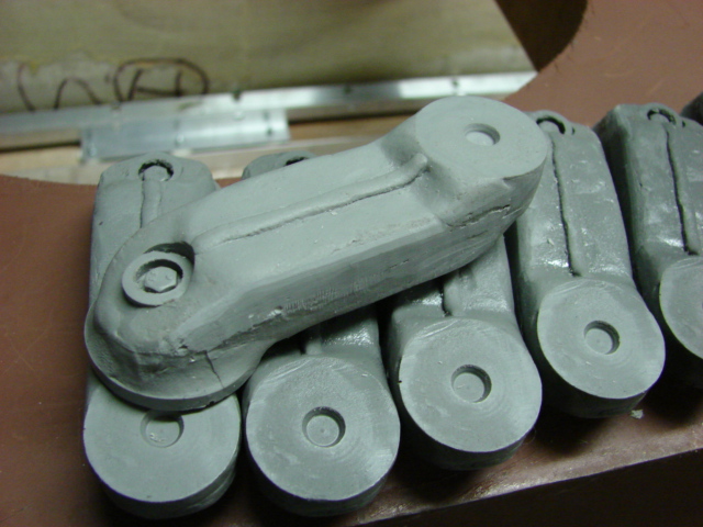
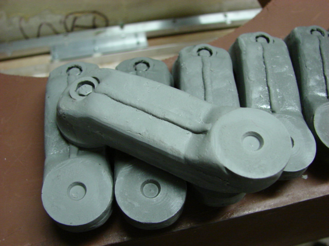
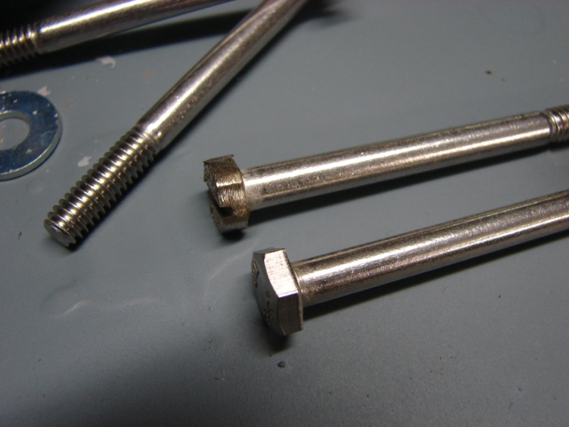
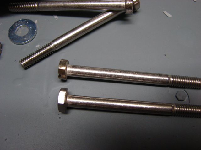
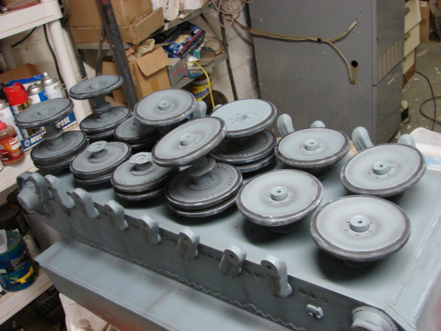
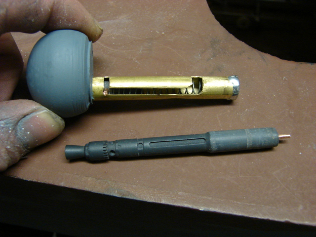
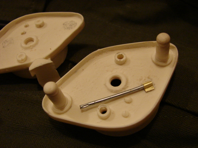
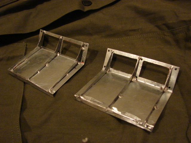
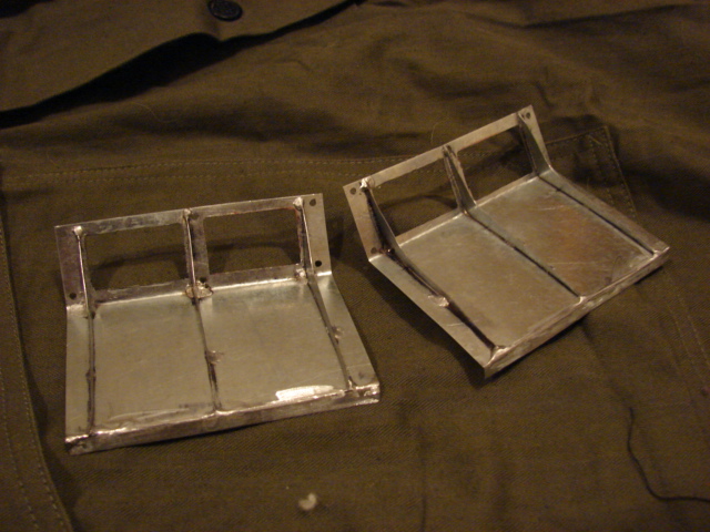
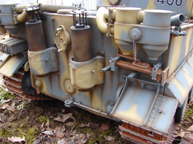
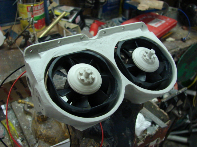
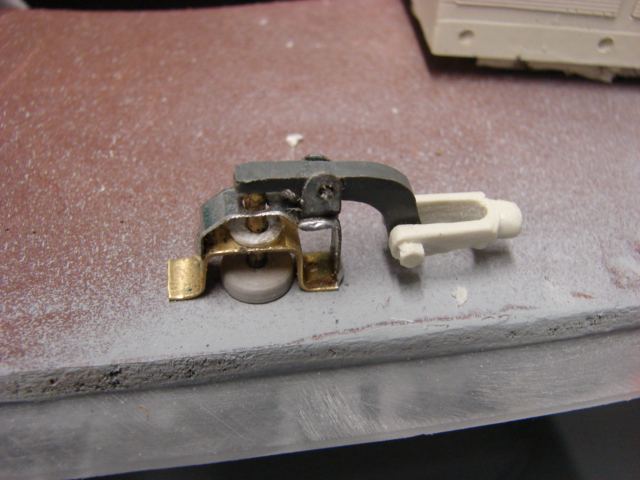
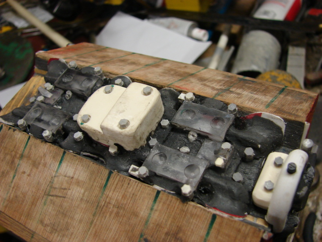
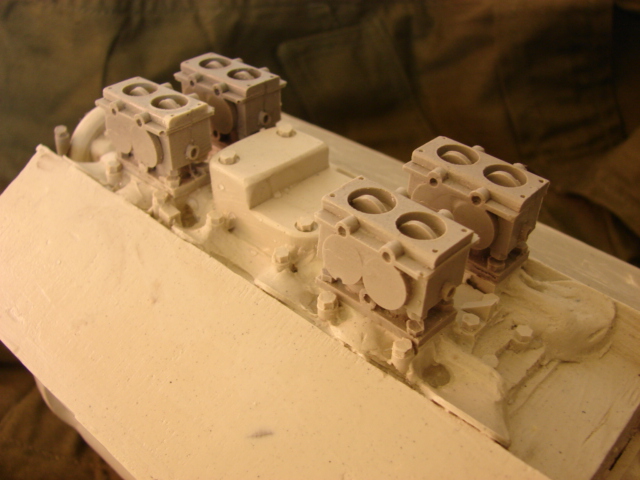
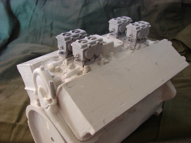
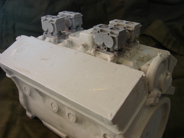
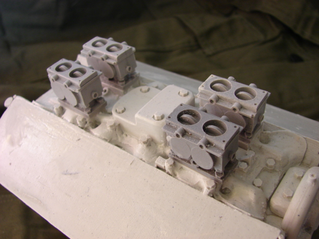
I have built one of these hulls before in my last tiger I project so I have some of the detail parts on hand which will save time

1/6th scale Tiger I 406

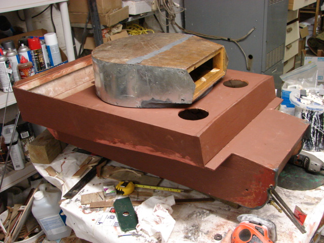
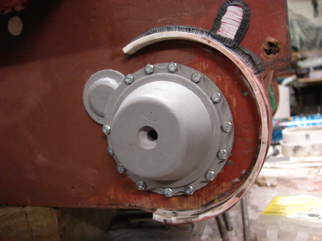
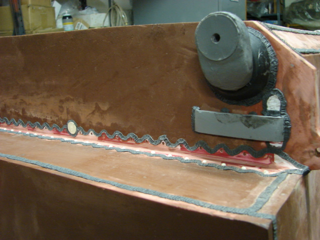
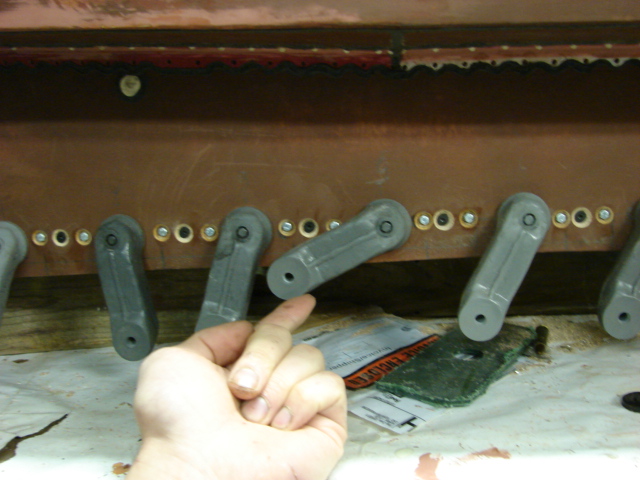
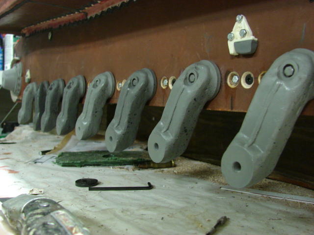
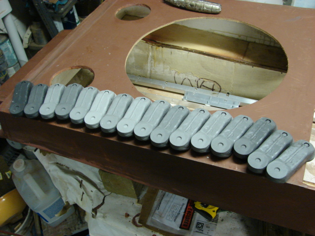
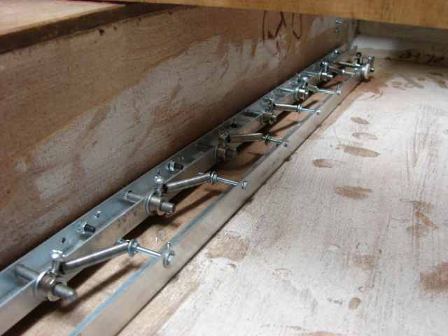
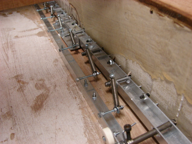
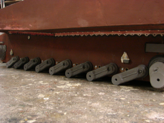
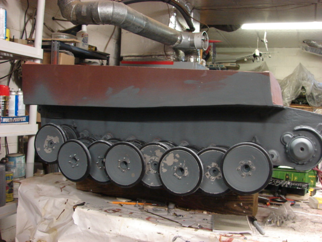
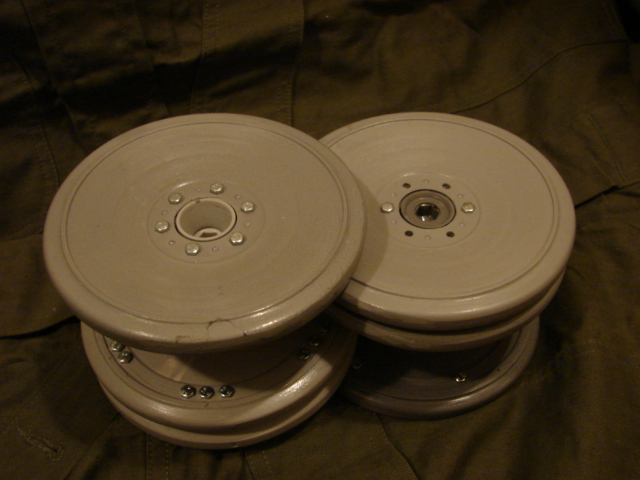
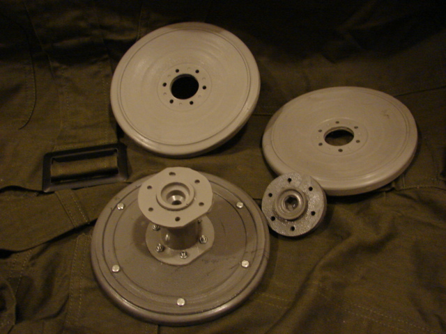
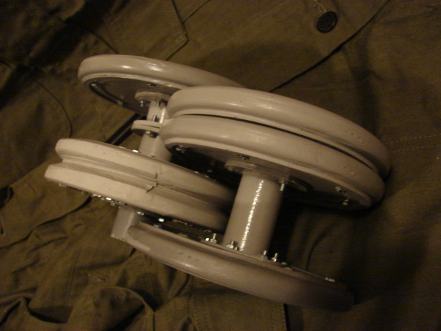
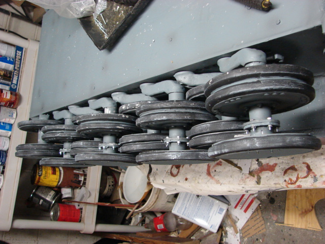
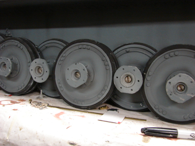
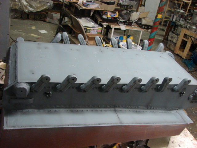
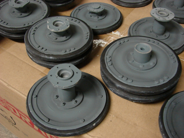
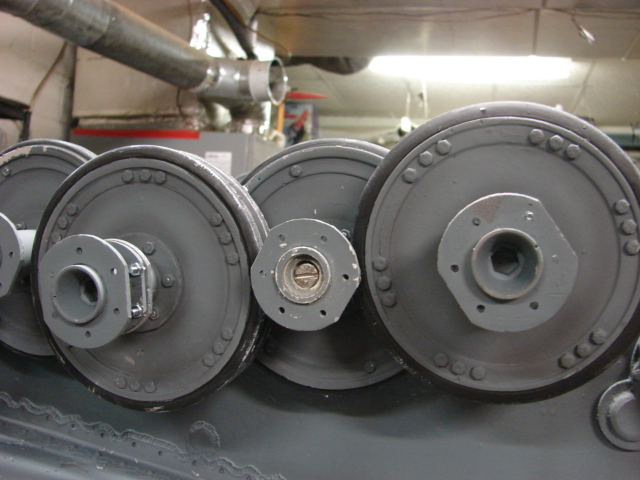
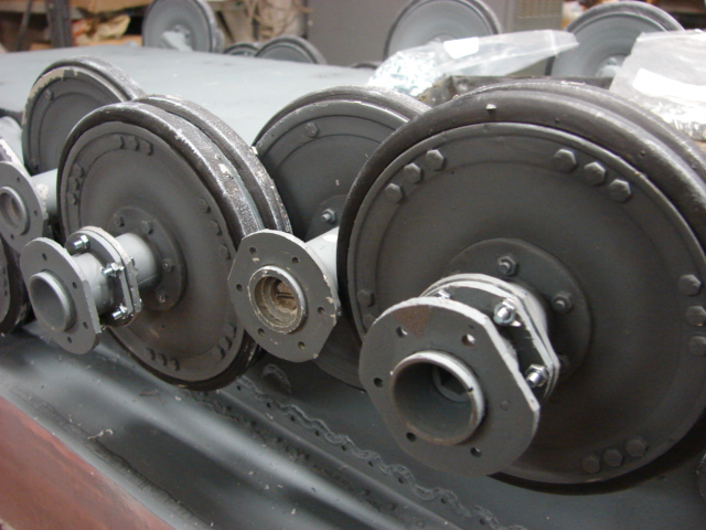
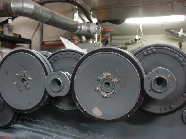
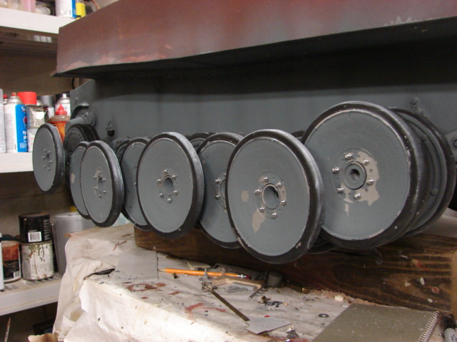
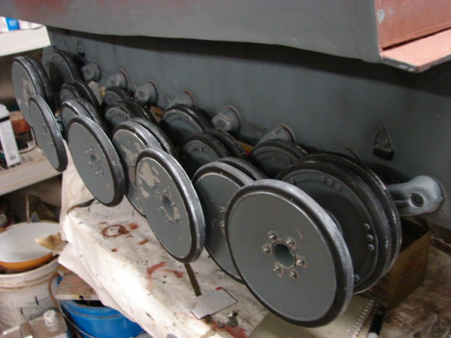
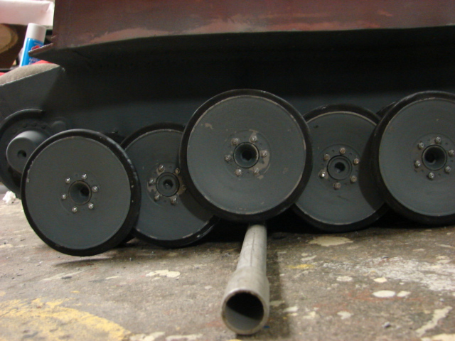
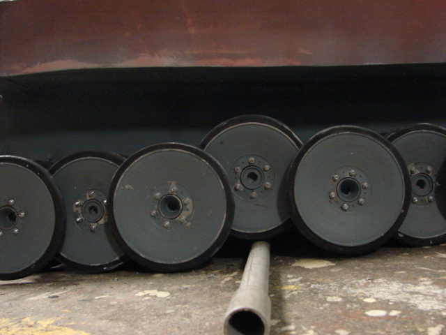
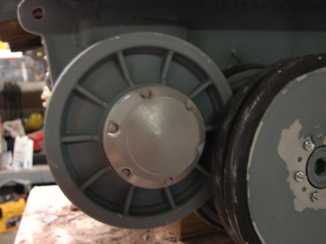
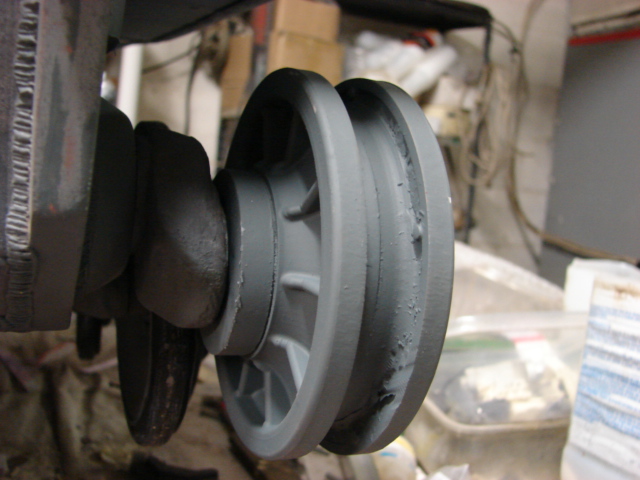
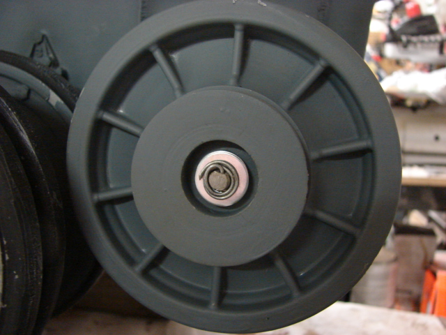
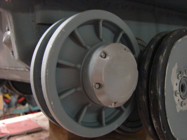
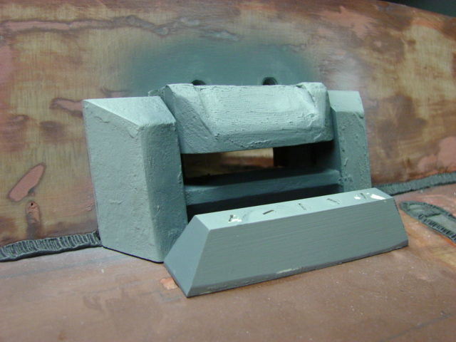
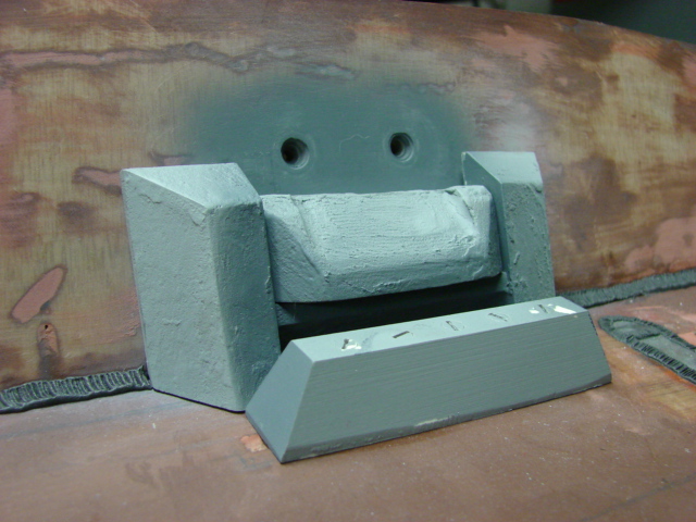
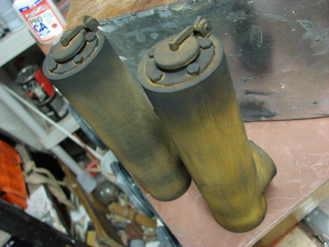
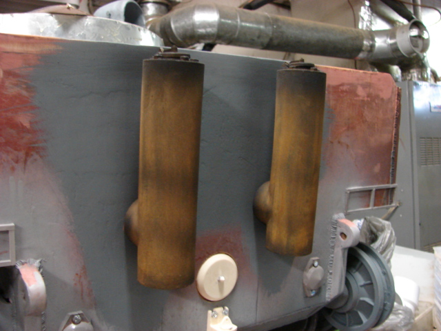
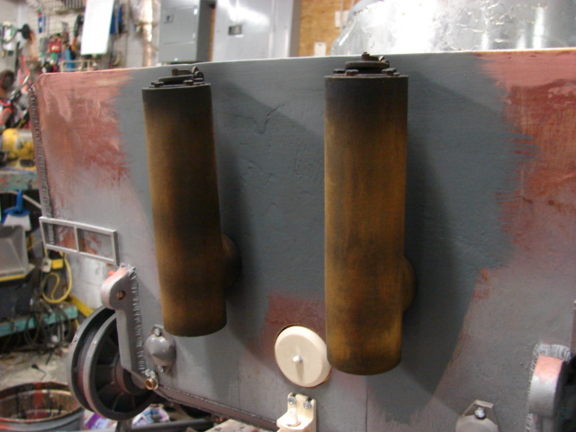
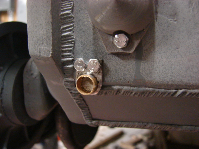
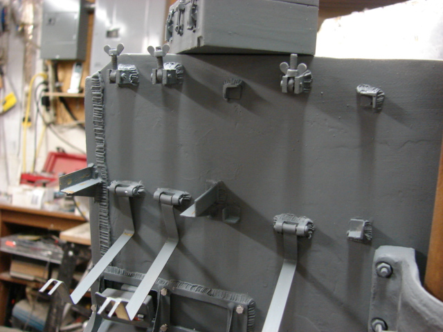
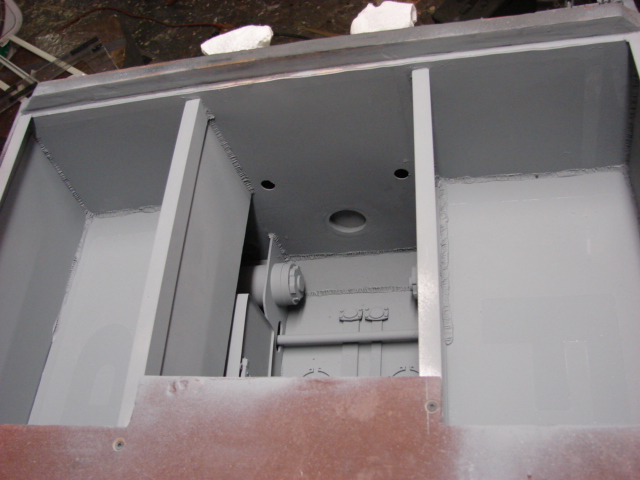
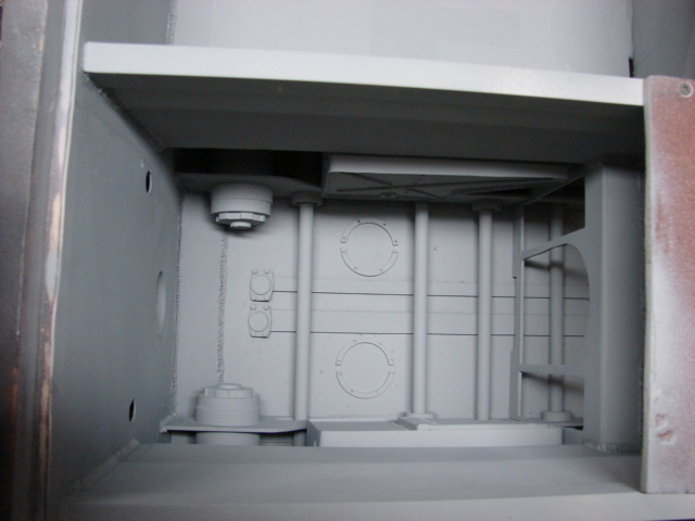
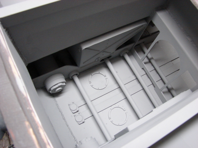
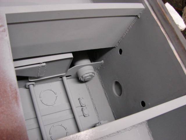
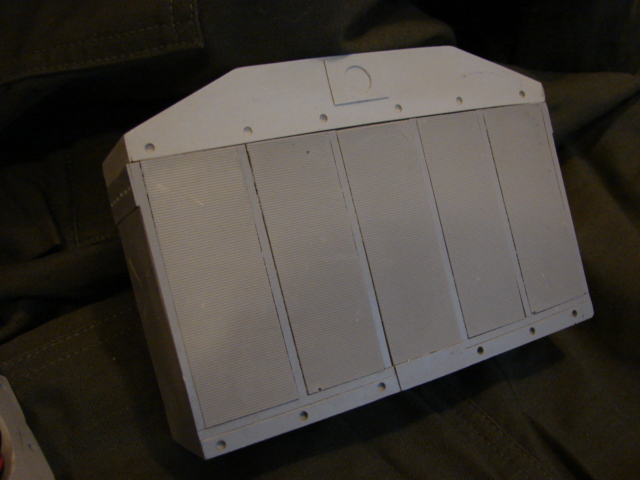
With the basic hull complete I will now be focusing on the tank’s lower hull detailing. These would include the final drive guards, final drives, angle brace, welds and ilder mounts. Once complete I will be working on the tank’s suspension.

I have a lot of special plans for this build as well as some very special detail parts in mind to produce. More progress and info to follow!

Progress has been slow this week due to my hectic schedule, but some small progress has been made to the model.

The tank’s lower hull welds were completed. The lower hull support angles were also added complete with dome rivet detailing. On the tiger I only the top sponson portion of the angle had the rivet heads exposed, On the side hull portion of the angle a hole would be visible. In addition to the angle the shock absorber mounts were added to the lower hull sides.

Because this tank will not be receiving the side skirts, the support angle and other lower hull details will be visible

On the tank’s front portion the resin final drive transmission hub and the final drive armor collar were mounted.

On the tank’s rear portion I have mounted the tank’s idler mount system.

All of these parts have been added to the Tiger I product line. East Coast Armory – 1/6th Scale Tiger I Detail Upgrades

New tooling Resin Tiger I track aligner blocks.

Resin Adjustable Tiger I rear idler mount system set. This set allows you to adjust the track tension on the tiger’s rear idler mount via a wrench. The mount also allows the idler to hang properly from the rear hull.

A youtube video was made with the new progress

1/6th scale Scratch built German Tiger I Tank project video #1 (project Start) - YouTube

With the final drives and the idler mount system out of the way I can now start on the tank’s functional Torsion bar suspension. My schedule will be clearing up this week which will allow for more work time and faster build progress. More progress to follow.

Very, very cool indeed.

I am assuming from your description you are going to build her as a memeber of either the 501st, or 502nd?

I will be building my tank with the two side turret bins like the one from the DML Leningrad tiger I kit.

I have completed the tank’s functional suspension.

The torsion bars have also been added to the product line.

East Coast Armory – 1/6th Scale Tiger I Detail Upgrades

To make the torsion bars functional I used a similar system that I developed on the Jadgpanther.

In addition to the suspension I also added a set of my resin bump stops.

The suspension can hold up the tank’s weight when placed on the ground.

Note the swing arms are that are located on the left hand side swing to the front, while the arms on the right hand side swing to the rear.

Now with the suspension out of the way I can now focus on tooling up the tanks early wheels. More progress to follow.

The tank’s suspension is now complete.

The last of the wheel components were created and the wheels have been added to the product line. http://www.eastcoastarmory.com/tiger.htm

TO mount the wheels to the swing arms I used long necked bolts that were concealed in side the wheels axles. These bolts allow the wheel to spin freely, but secure them securely to the swing arm. Prior to mounting the bolts needed to have some mods made to them.

The bolt’s corners were ground off. A slot was also cut into the bolt head via an angle grinder. Because of the confined space of the wheel stem a screwdriver will be used to thread the bolt onto the swing arm. A drop of epoxy was also used on each of the axles to keep them in their proper place.

Prior to the wheels being mounted the tank’s lower hull and the wheels were painted in their primer and base coats. The rubber tires were also painted and weathered. Because of all the wheel layers and I airbrushed the weathering on the tank’s lower hull and the inner portions of the wheels. These areas will be very restrictive when assembled / installed.

To install the tank wheels, you have to mount them in layers as you would on the real vehicle.

Layer 1, Inner wheel sections

Layer 2, outer wheel Hubs

Layer 3, Inner wheel end sections

Layer 4, outer wheel end sections.

The suspension rolls smoothly, and articulates over obstacles very well.

The wheel Zerk Fittings are casted, but will be added after the tank is painted.

A project update video which shows the suspension in action has been posted on youtube. 1/6th scale Scratch built German Tiger I Tank project video #2 (Wheels and suspension) - YouTube

With the suspension out of the way I will now be focusing on the tank’s sprockets and idlers, which I already have. Once complete I can then move on upward to the tank’s upper hull detailing. More progress to follow!

Road wheels are a nightmare in 1/35…I can only imagine what they would be like in 1/6! The working suspension looks like a mechanical innovation while still supporting the weight, very effective. [Y]

I’m sure that everyone seeing this post is impressed, but it’s just so far out from what we do here in terms of scale and dimension that it’s hard to relate to!

Still, it’s amazing work. I just would love to know what you do with these behemoths once you’ve finished them? I mean–do you have a garage or a barn you keep them in?

I am in absolute awe of these projects! The skill and time it takes to scratchbuild all the parts is mind blowing. I have to tell you though, I would give anything for the opportunity to paint something in that scale. Talk about being able to micro manage the paint job!.. wow, One can dream! I can see this early Tiger in a scruffy white wash!

Cheers!

Thanks guys,
doog, All of the builds that I post are in my personal collection. Once finished I store them in my shop, or anywhere else I can squeeze one. typically I keep them covered with tarps to keep the dust off.

wbill, The wheels were very challenging to design, but were also fun to create. it is a good feeling when you spend lots of hours designing, machining, and molding a component to see it come together in the way you designed with no hick ups.

I have made progress on the tank’s upper Hull.

The tank’s sprockets and Idlers have been fitted. For the tank’s idlers I modified a pair of FOA ABS plastic idlers.

For the tank’s idler mods I had to delete the rear molded in hub cap, and to carefully remove the molded in front hub cap. The wheel was filled with resin to make it a solid unit. Once solid I was then able to bore out the recess for the retaining bolt system. two resin and PVC discs were added to the front portion and the rear portion of the idler. The discs give the proper protrusion of the idler hub cap.

To mount the idler wheel I used the same lock pin system that I use on my other builds. The system allows for the wheel to be mounted securely, but also allows the wheels to spin freely.

Progress was made to the tank’s front armored plate details.

All of the plate welds have been added, and the front plate bosses were mounted

The tank’s driver’s retracting visor assembly have been mounted.

A small piece of lexan was mounted on the interior to simulate the panzer glass.

The small back up vision ports were mounted. The mounts have their recessed reduction ledges machined in. On the later production tigers these vision ports were welded shut.

The tank’s bow MG ball was also mounted. the bow mg can pivot, and for the MG barrel I used the resin panzerwerk set.

Because I will be making the tank’s snorkeling equipment I will be fabricating the bow MG cover. Because I will be making the cover I needed to do something special with the bow MG. Rather than making the MG barrel removable I decided to make the barrel retract instead. The barrel is spring bound and locks into tow positions. One exposed for standard display, the other in the retracted position for when the cover is added.

progress was also made to the On the tank’s rear hull details.

The tank’s exhaust stacks were completed, painted and weathered.

Because this model is an initial production version of the tiger the exhausts don’t receive the cage guards that are present on later vehicles.

Prior to installing the stacks The tank’s hull was prepped with the base coat and the weathering.

After the prepping the stacks were added.

Along with the exhausts the idler tension cover caps, fender mounts, rear reflector mount, engine starter cover cap and tow hitch.

a project update video was also uploaded to youtube.

http://youtu.be/Ds0cvpCHkOM

I will now be focusing on completing the tank’s rear details like the fenders, tool boxes, tail light…etc. More progress to follow.

I have completed the tank’s rear wall detailing.

The tank’s functional tool box and Jack block mounts were added. The straps are fabricated out of brass strip. On these initial production tigers the Jack block was mounted on the rear wall as opposed to on the tank’s top deck besides the front air blower which was on later production vehicles.

The tool box was mounted vertically with two straps. With the addition of the fifel system the tool box was moved lower and was placed horizontally on a metal shelf that protruded from the hull.

The tank’s functional Jack mounts were also added.

The tank’s alternate antenna base has been fabricated. These mounts were never used and were replaced on later production vehicles.

The tank’s starter plate was added as well. The plate itself was back dated to the initial version from my early version.

The differences between the two are that the initial version is missing the clutch rod and mount.

Another difference with this component is that the plate mounts to the hull in a different angle.

The tank’s mud flaps were also mounted.

The flaps are all fabricated out of sheet steel and have been added to the product line. http://www.eastcoastarmory.com/tiger.htm

The initial tigers had two versions of mud flaps. The first was this version, later when side skirts were added a small extender was added and was bolted to the mudflap and connected to the side skirt. These mudflaps are not hinged but are bolted to directly to the frame.

Later this design was replaced by the hinge design that was common place on tigers.

The last bit that was added was the tank’s rear black out notek tail light. For this component I used a Dragon Notek light that was a spare from the schiwmmwagen kit.

The light was modified by adding painted clear plastic lenses for the red, orange, and green lenses. After I added the lenses I decided to also throw in a spare LED that I had on hand making the light full function.

Now with the rear wall details completed I can focus on the tank’s grill work. More progress to follow.

Progress has been made to the model’s engine compartment.

Because this model will not be getting the fifel system or the grenade mesh grills covers I can get access to the tank’s engine compartment and have plane view of the fans. Because of this I decided to give the tank a full engine compartment interior including the engine and radiator/ fan work.

Before I can start on the interior details I first had to construct the engine bay itself, The bay and all of the lower hull interior details are fabricated out of plastic, lexan, and aluminum.

all of the major lower hull interior components were added, torsion bars, bulkheads, air ducts, idler mounts, and the lower fuel tanks.

The trickiest part of scratch building the interior was to conceal the working suspension system with the detail parts and still keeping the suspension functional.

More interior components (fuel lines, fire fighting equipment, exhausts cooling ducts, water drains…etc) will be added to the compartment very soon.

A project update video was also uploaded to youtube.
1/6th scale Scratch built German Tiger I Tank project video #4 (engine compartment) - YouTube

In addition to adding the last of the compartment details I will now be working on the masters for the fans and radiator. More to come!

I focused on the tank’s radiator and cooling fan cluster.

I now have 90% of the components complete and am now finishing up the last of the fittings and right hand side air breather radiator cover. Once complete this set will be added to the product line. Until then here is a sneak peak of the set.

One unique feature that this set will have is the the fans are full function and are electrically powered. This will give the model a nice detail element, and if the tank is RC the fans will help pump cool air into the vehicle.

Along with the cooling system I fabricated the tank’s rear engine compartment drain water plug. The plug is all fabricated of brass and metal.

The tank’s fire wall sliding access plate was added as well.

The last bit of detail that was added was the tank’s exhausts cooling manifold. The snorkel tube will be added very soon.

I have started on the engine and once the last parts of the cooling system are complete I can focus on the engine in full steam. More progress to come.

Thanks guys, The last of the molds are now complete and the sets have been added to the product line East Coast Armory – 1/6th Scale Tiger I Detail Upgrades .

For the right hand side cluster the radiator fillet gap differs, On the right hand side the cap is in a recess, and is bolted on to the cover. The pressure release tube is also located on this cap. All of these features are built into this set.

I was able to complete the set and it ready for my model.

The coolant tubes are also included with the set.

With the clusters now complete I can now focus on the engine! Stay tuned!

It has been a while since I had any progress on the model but I have been working on the tank’s engine master. Currently I have completed the master for the crank case. So here is a sneak peek of the engine.

I was originally only going to create the HL-210 which was only used on the initial / early tigers, but after a several request emails I will also be creating the HL 230 engine which was used on most of the german tanks. Since both engine blocks are so similar both kits will use the same crank case, but will have different components (rocker arm covers, air filter manifolds, starters… etc.)

I should have the 210 engine masters complete in about 3 weeks. More to come

Speech-less… !http://www.kolobok.us/smiles/artists/mini/connie_mini_byebye.gif

Thanks,

I have completed the molds for the crank case, lower engine plate and the carburetors. Currently I’m finishing up the rocker arm covers and I will soon be on the air cleaning system. Once the masters are ready I’ll make the molds and cast up a sample set.

Hey AG,

First off I have to say I’m glad I’m not on dial-up with all these great photos [;)] and secondly I have to admire your dedication to your work. It’s great stuff. I mean, I prefer kits that can assembled on my bench and stored in a glass cabinet in my bedroom but that’s just me! Each to their own! I build 1/35 and you build 1/6.

Your website is a great read btw.

Your attention to detail is brilliant and I like the fact that you have actuallt bought the Dragon Initial kit as a reference (what will you be doing with that kit on completion of this behemoth) [:P] [;)]

I’ve just finished building that very same same kit - I built it as Tiger ‘100’ with the side bins. It was my first proper 1/35 Tiger build and I thought I’d start very early then mid then go onto a late build. I’m hooked on Tigers now. I loved my build and it’s a personal favourite to boot!

Are you going for this version? :

!(http://i806.photobucket.com/albums/yy343/Hinksy1/Models - October 2011 onwards/CompletedTigerI100170312008.jpg)

!(http://i806.photobucket.com/albums/yy343/Hinksy1/Models - October 2011 onwards/CompletedTigerI100170312020.jpg)

Good luck with the final assembly stages and the painting/weathering and keep the updates coming!

All the best,

Ben [t$t]

Thanks Ben, Most likely the 1/35 model will be built, or placed back into the stash. Believe it or not I don’t build as many 1/35s anymore because I’m out of 1/35 space

It has been a while since my last post, but I have been working on lots of small engine bits and masters. Currently I completed the engine’s rocker arm covers. There are many more smaller parts that are currently in molding. Once ready they will be added to the engine.

The rocker arm cover castings are going to be used on both the 210 and the 230, but there will be different components to add on to the covers that will make them different

Currently I have the rocker arm parts for the 230 complete and the 210 parts are currently in molding.

with the next update I will have more parts complete that once added will distinguished the two engines from HL 210 to HL 230. More to come.

I got some progress on the HL 210.

[img]http://eastcoastarmory.com/forumPic/lenningrad_tiger/master/air_stacks/DSC00399.JPG

One of the key differences the HL210 has from the HL 230 is in the arrangement of the top engine details. The HL 210 has it’s magnetos mounted to the top of the rocker arm covers on two long arms. On the other side of the arm are two air intake stacks. On the HL 230 the magnetos are mounted to the fan drive gear box which is located on the center portion of the engine.

The HL 210’s air cleaner manifold system is also different from the 230. On the 210 all four carburetors are connected to one large air duct. On the top of the duct three smaller air filter canisters are mounted. On the 230 the single air duct and three canister system is replaced by two smaller ducts and two larger air filter canisters.

To power the tank’s cooling fan / radiator system a gear box emerges from the rear of the engine. On the end of the gear box housing is a out put wheel which wold be bolted to a drive shaft, that would power a small transmission that would spin the cooling fans when installed in the tank. On the 230 the gear box set up was altered in that rather than having there be one out put shaft that emerges from the center. Two out put shafts would emerge from the gear box sides. Each of these two output shafts would then be connected to dive shafts and each would power a transmission that would power the cooling system.

Both engines share the same magneto, and exhausts manifold system. I’m currently working on the 230 air intake system, and gear box/magneto cluster.

Once complete I can move downward to the exhausts, starter and oil tank. More to come!

Amazing work, the best scratchbuilding i have ever seen. You are one very talented guy,Massive well done[:D[