Thanks Guys, It has been a little while since I had any updates, but I have been working on the model in between processing orders and working on another non 1/6th scale project.
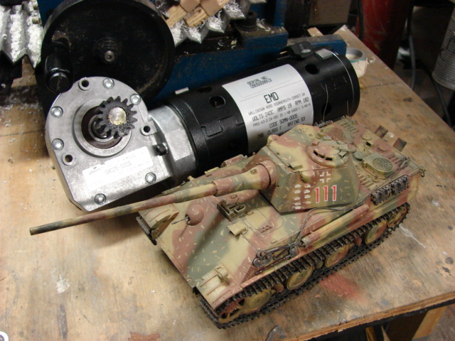
The Tank will weigh about 500 pounds once finished, which is why I can’t finish the model in my shop. I also have their early Tiger I which weighs about 300lbs and thier M4A3 which is the feather weight at around 150 to 200 lbs. All of these models are RC.
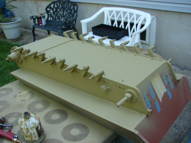
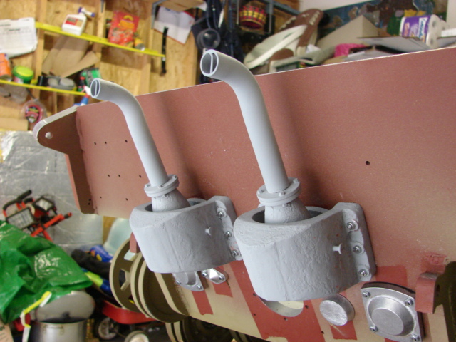
The tank will be painted with an ambush cammo pattern, but that won’t be for a little while.
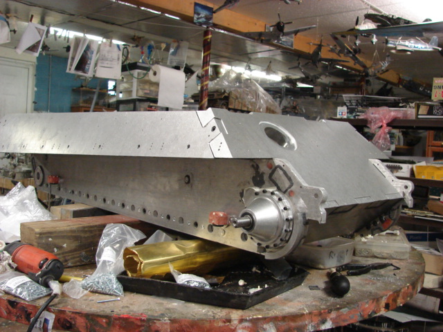
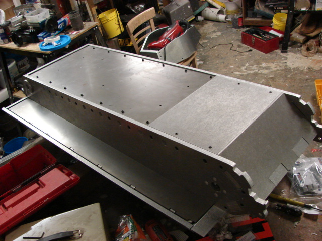
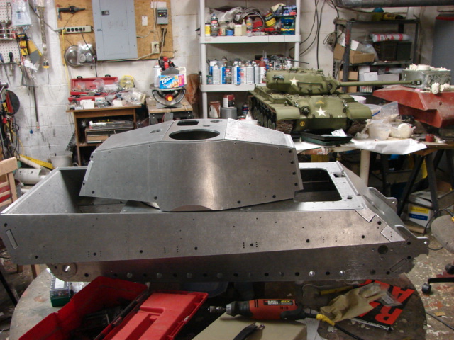
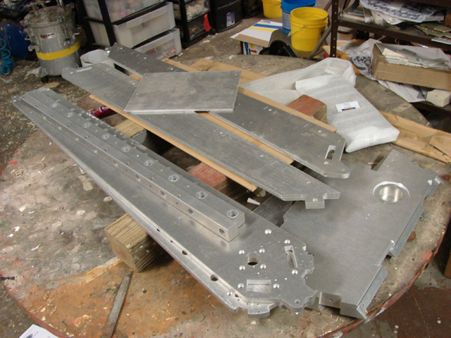
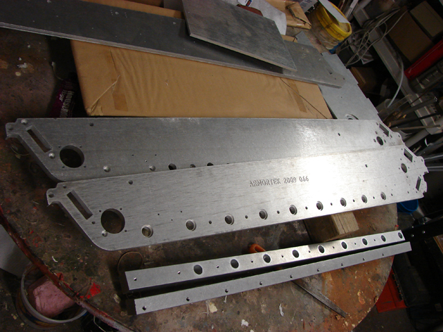
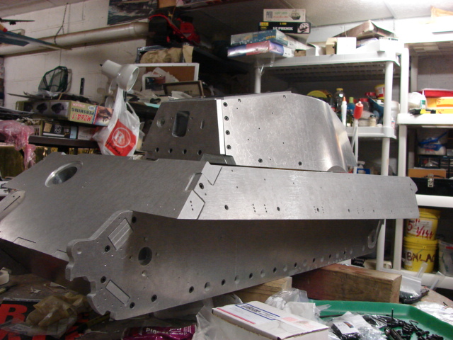
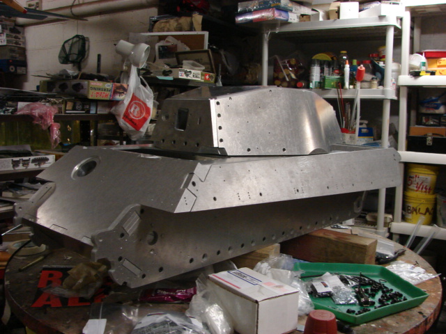
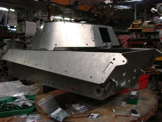
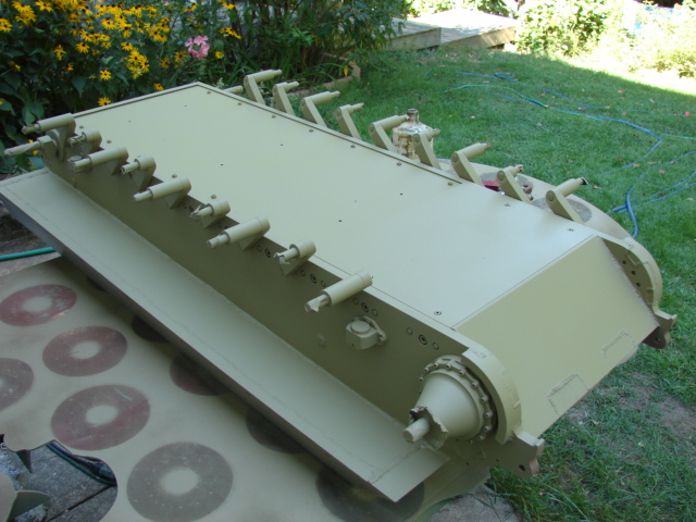
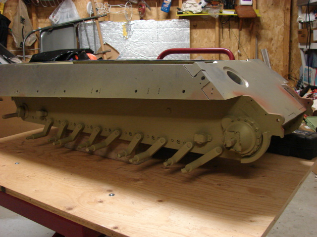
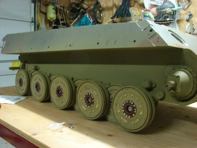
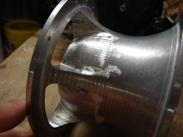
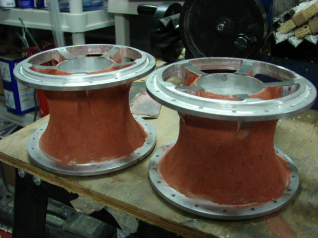
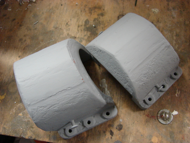
Since my last post I have been working on the tank’s lower hull, and getting it ready for the suspension, and a coat of primer.
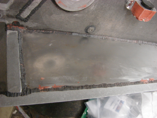
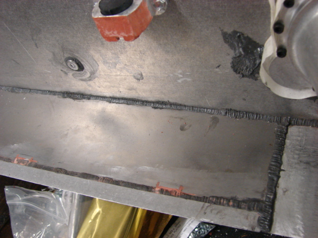
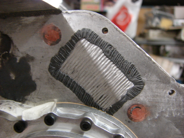
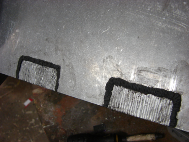
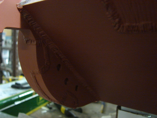
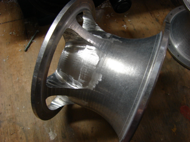
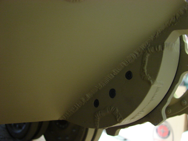
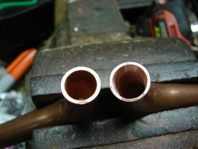
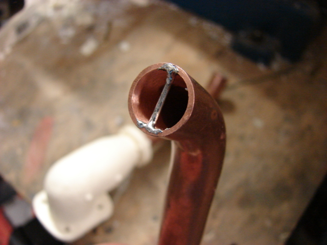
The tanks lower hull seams were all cover up with sculpted epoxie weld beads.
Before
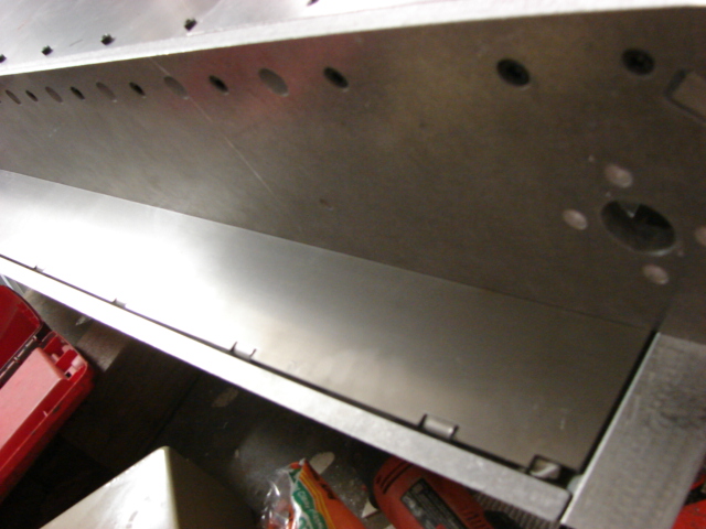
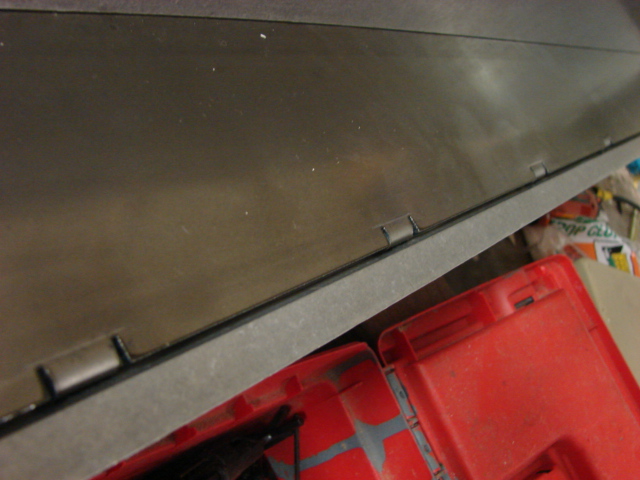
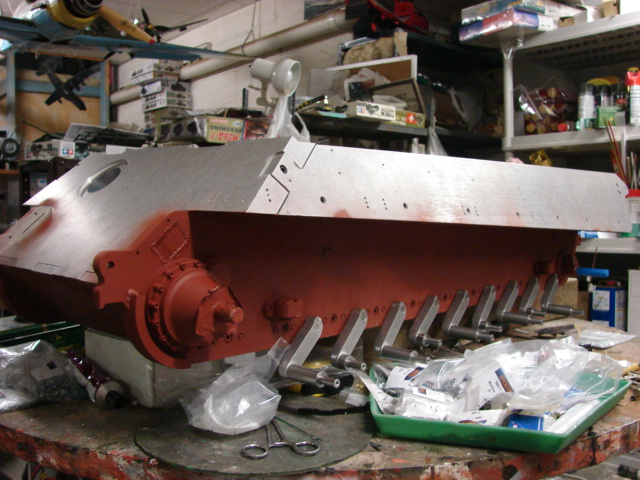
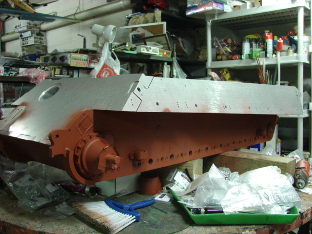
After
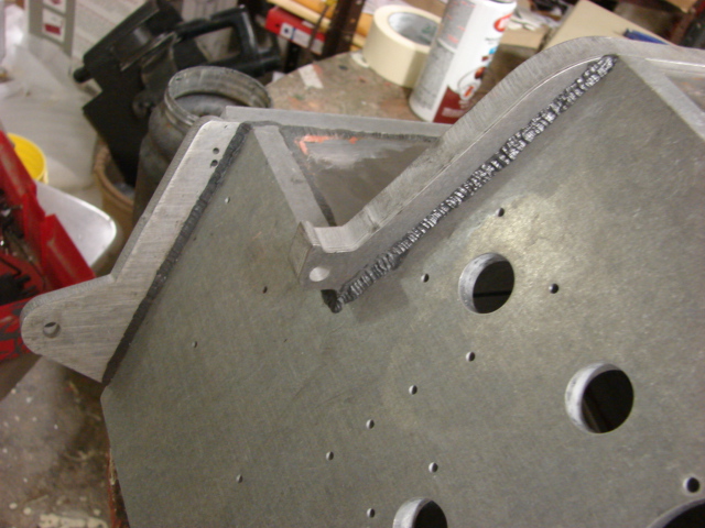
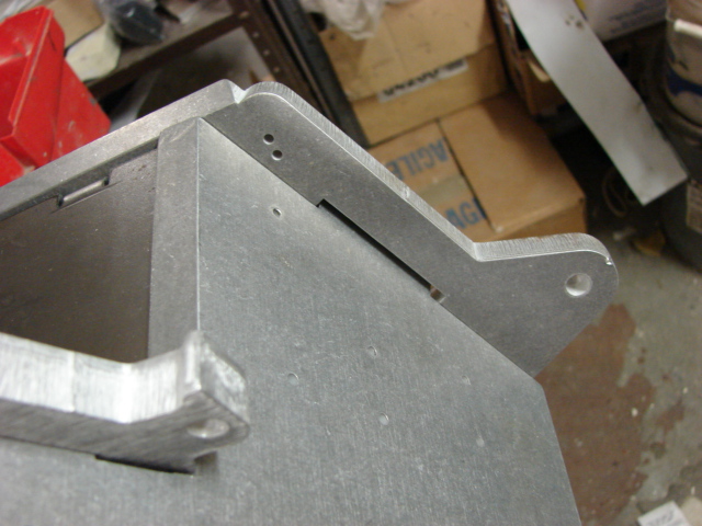
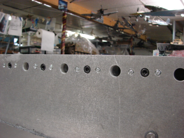
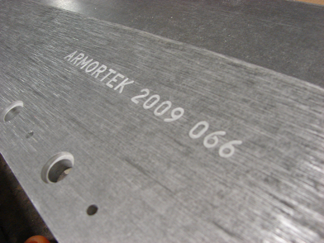
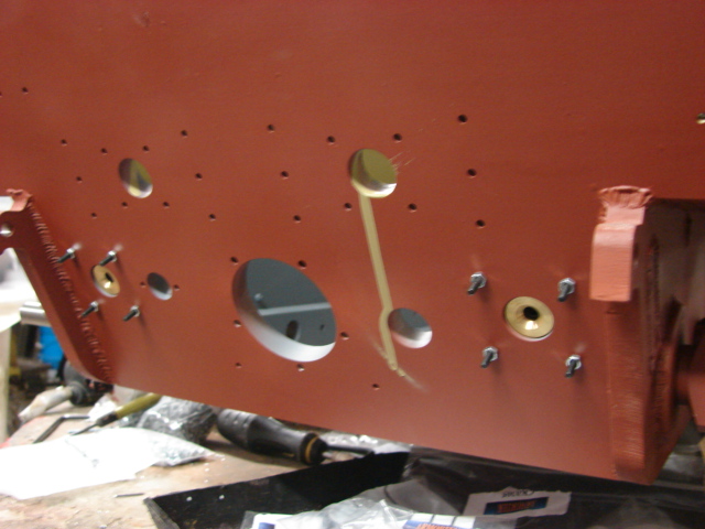
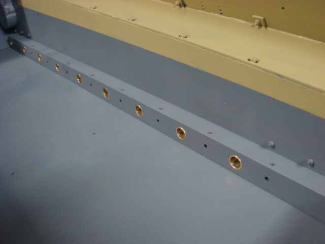
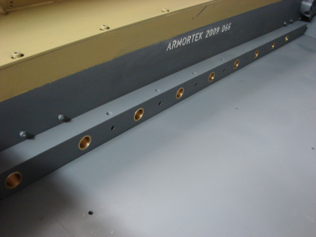
Along with the welds I have been plugging up the bolt holes, and added the torch cut lines to the intersecting panels.
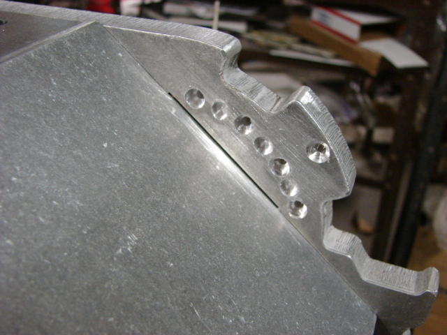
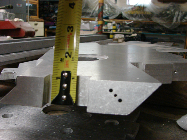
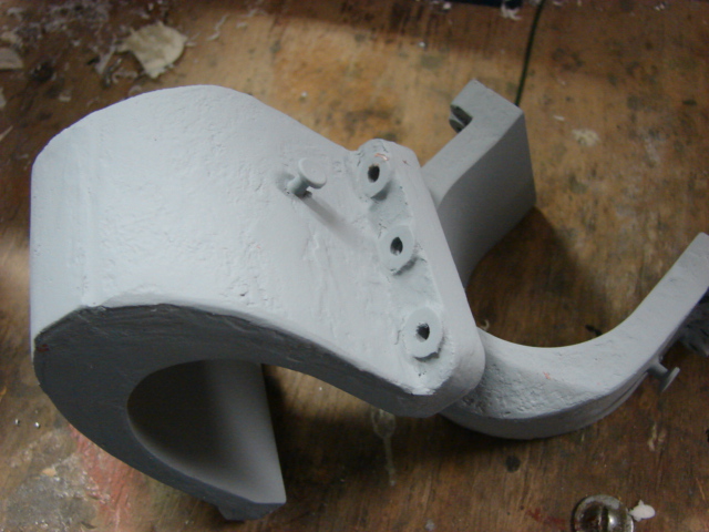
Along the bottom portion of the tank I added several recessed torsion bar bolt details. These bolts are found on either side of the reverse side of the torsion bars.
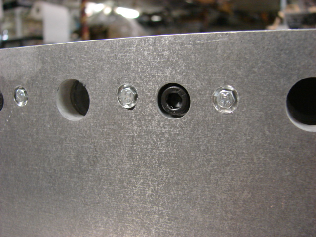
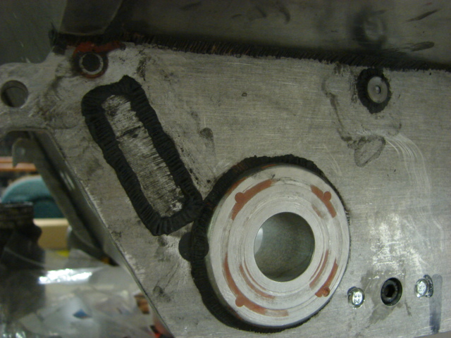
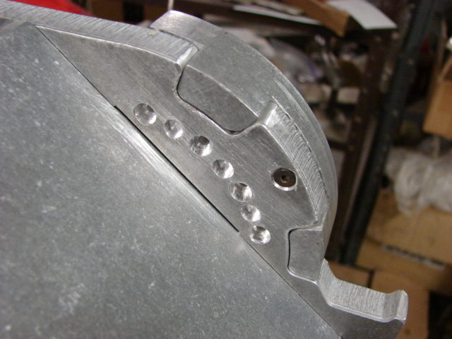
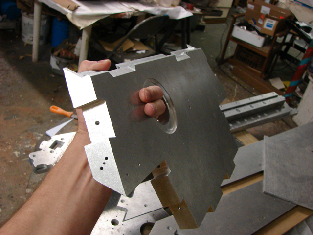
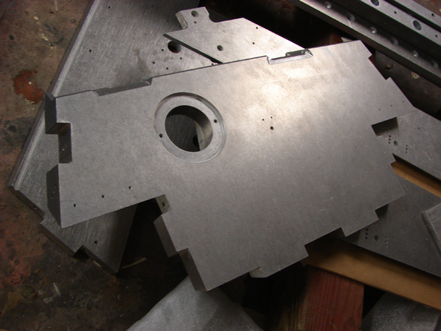
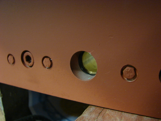
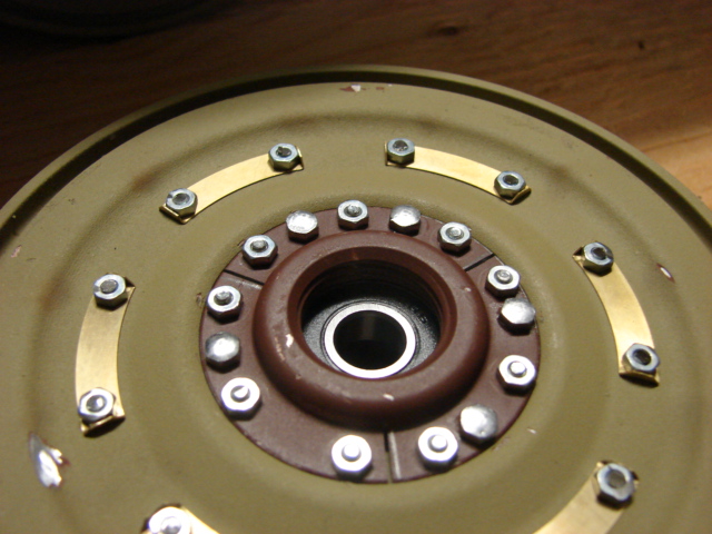
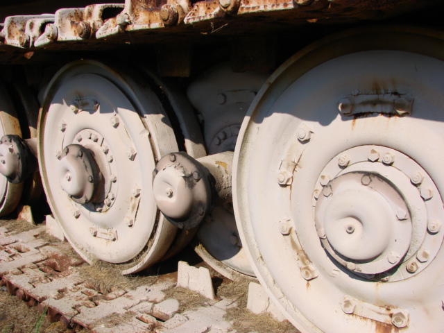
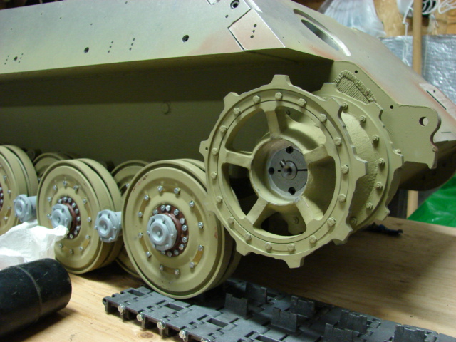
On the tank’s lower front portion the kit has four bolts that are used to mount the final drive hub to the tank’s hull. On the real vehicle there are three counter sunken cap screws, rather than four surface bolts. To correct this I drilled recessed into the tank’s hull for the new cap screw detail, and I drilled the recesses for the actual final drive mounts. When the final drives are installed the four bolts will be covered up with the body work, and the three cap screws will remain as detail only.
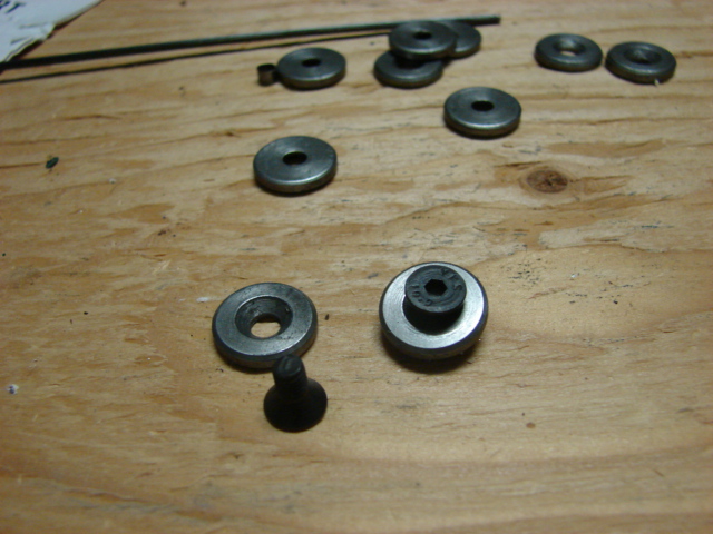
To mount the final drive armored rings to the tank the kit wants you to use a hex bolt. The hex bolt head that remains on the surface is not found on the real vehicle. To correct this I replaced the hex bolt with a counter sunk allen bolt, A counter sunk recess was added to the tank’s hull, after the armored ring is added the bolt will be covered up with putty. Welds will be added to this portion once all of the body work in this area is complete
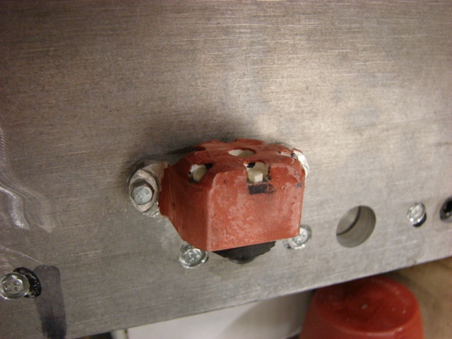
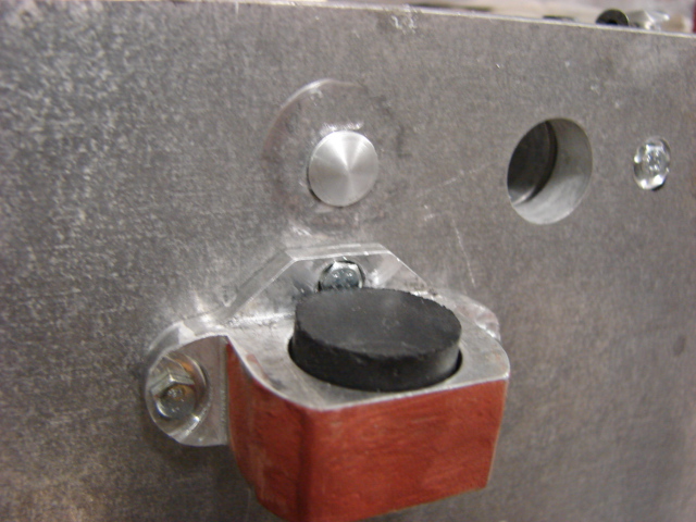
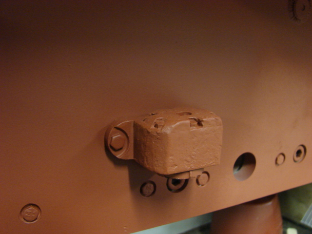
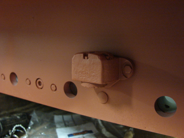
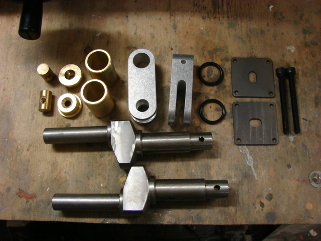
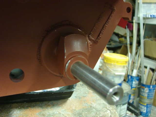
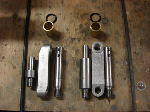
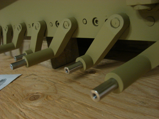
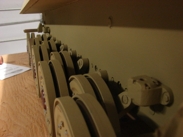
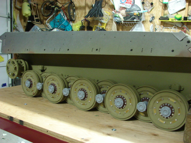
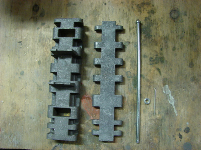
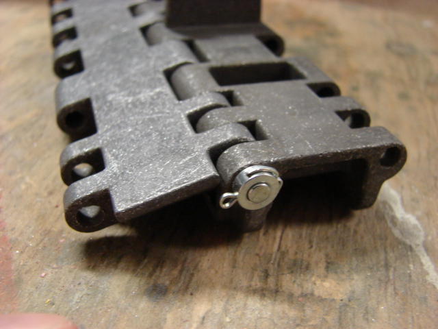
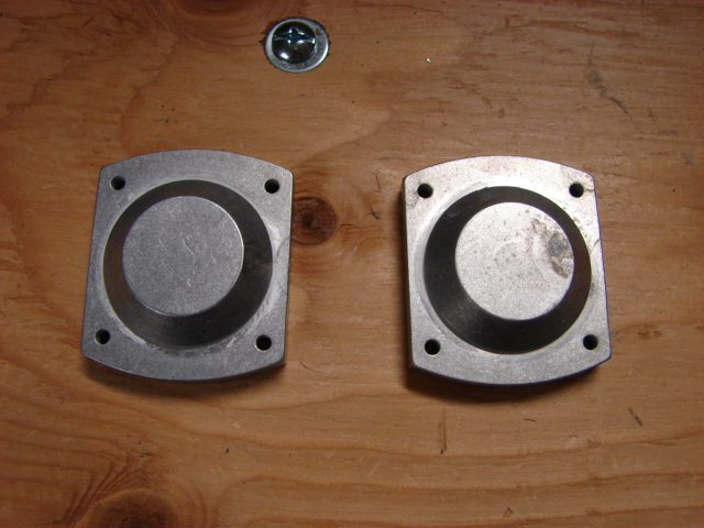
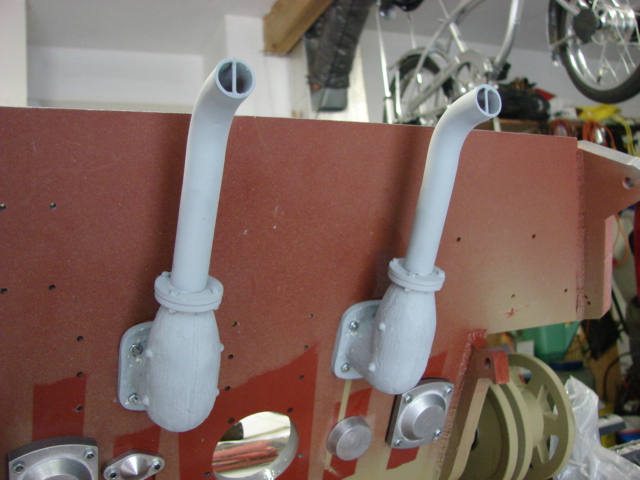
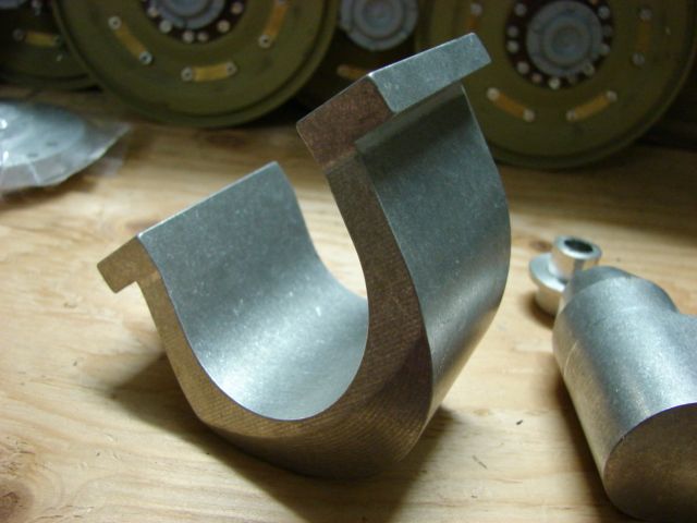
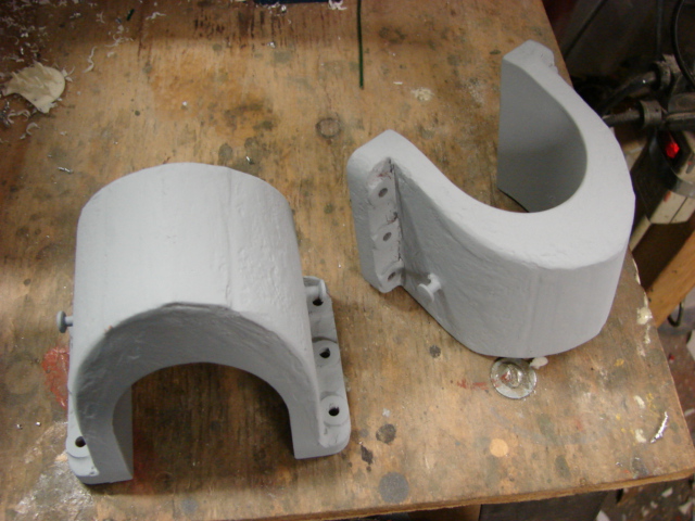
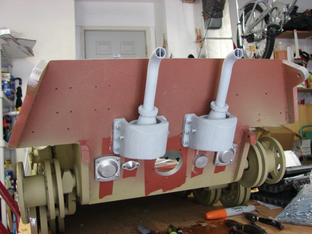
Unlike their older early Tiger I kit the King tiger kit supplies you with the tank’s bump stops. The bump stops themselves are very basic and a little bit of detail was added to them.
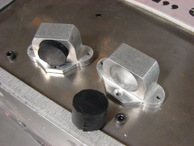
The bump stops are installed with cap screws, and the bump stop tops have a large cap screw protruding out of it.
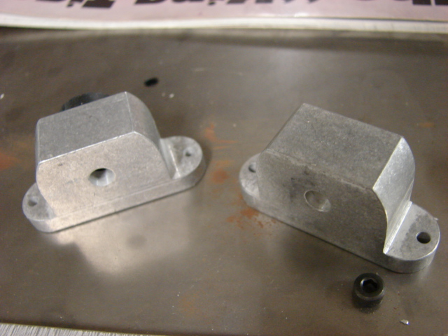
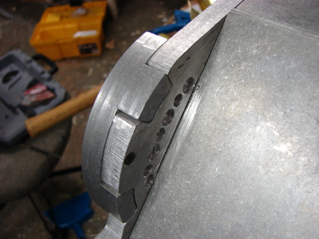
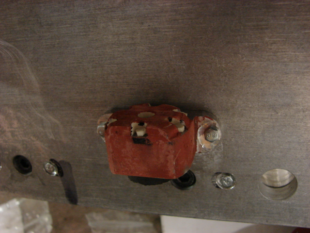
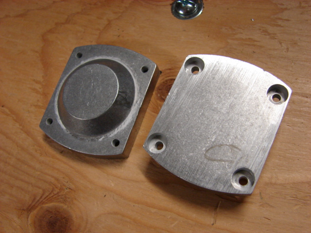
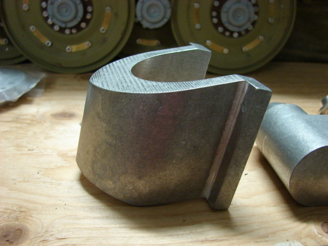
The stock bump stop has the overall shape and appearance of the real bump stop, but what was needed was to rework the bump stop frame, and re detail the bump stop top. To start on the bump stops sides I milled away a recess for the new bolts. A new recess was also milled into the bottom bolt hole replacing the counter sunk screw with the correct recessed hex screw.
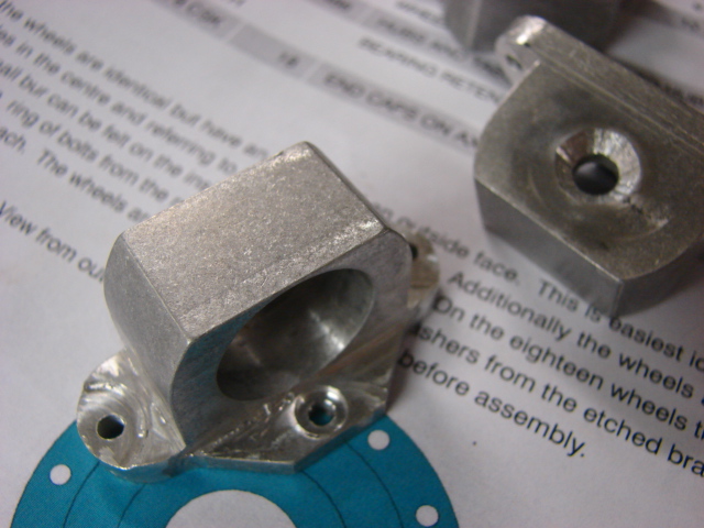
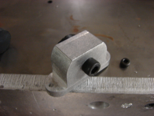
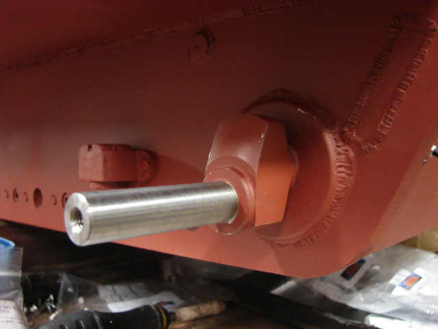
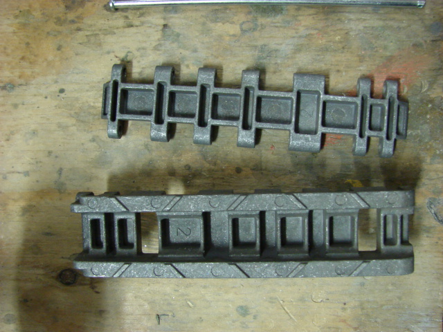
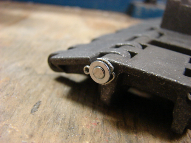
On the bump stop top to replace the cap screw I used a counter sunk hex bolt in it’s place. to do this I had to add the counter sink divot to the bump stop top.
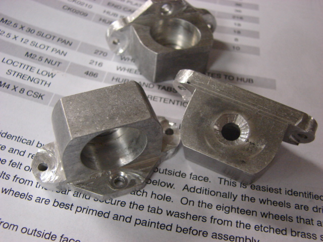
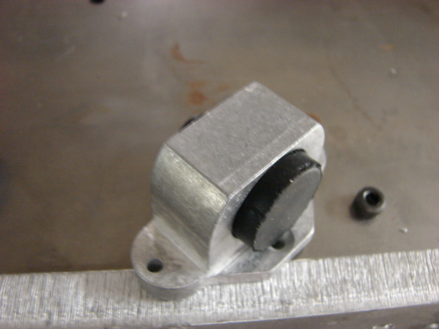
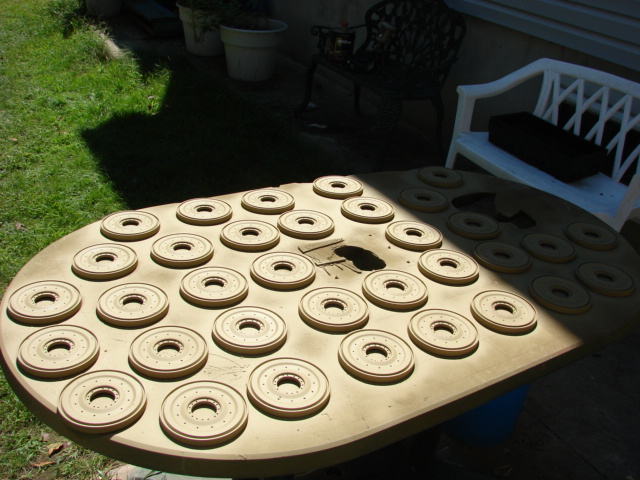
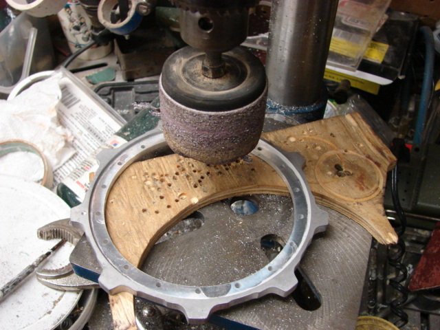
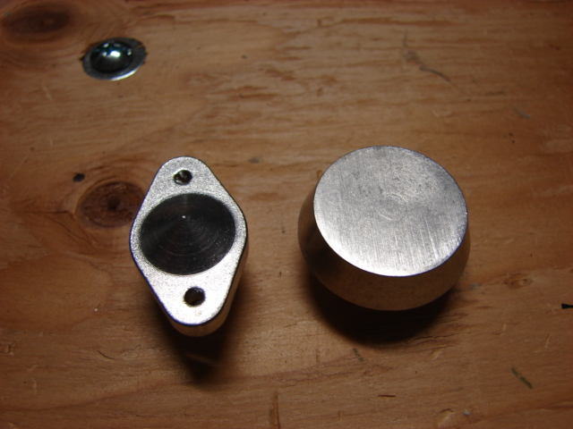
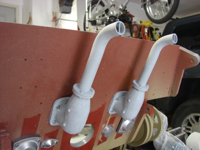
The reason for the bump stop top is because I machined a resin detail disc that fits over the entire bump stop top. In the resin disc I cut out the recesses for the small resin hex bolt details. a rough cast texture was also added to the bump stop frame and bump stop rein detail top.
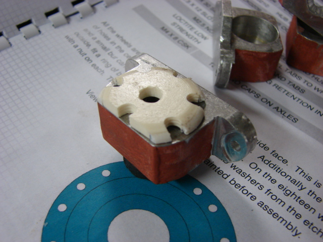
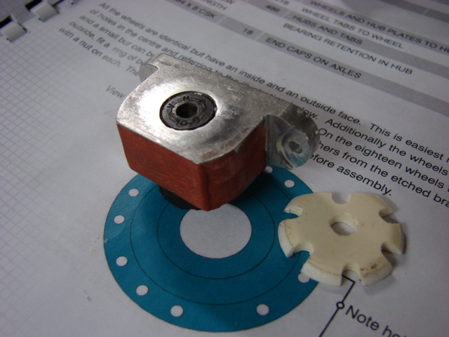
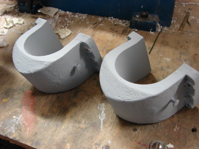
The real tank bump stop has more detail on them, which I could have added, but because this bump is not only for detail, but is designed to function I decided to leave the detail towards the top half only where damage is less likely to occur. In addition the top half will be the only part of this component that will be seen once the running gear and suspension are added.
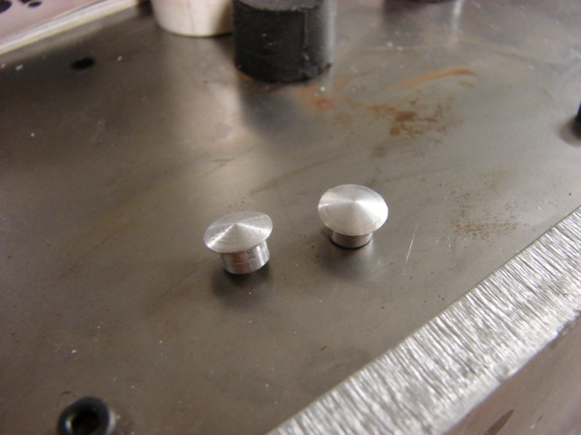
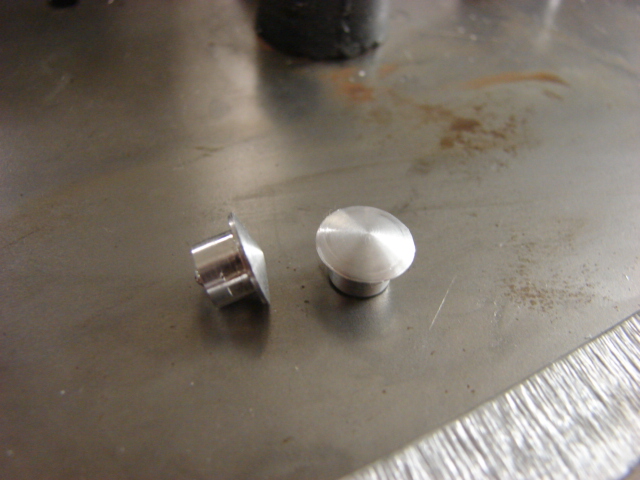
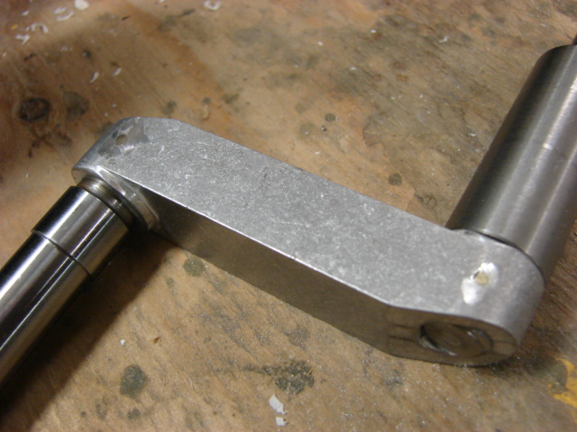
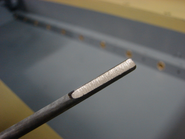
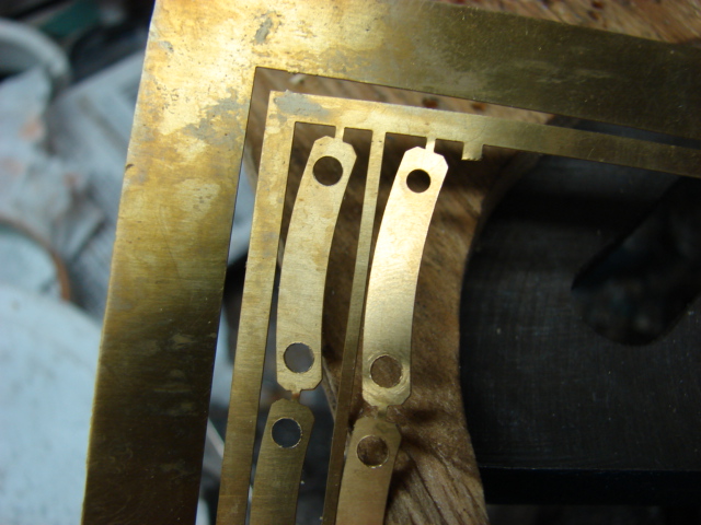
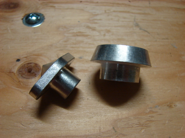
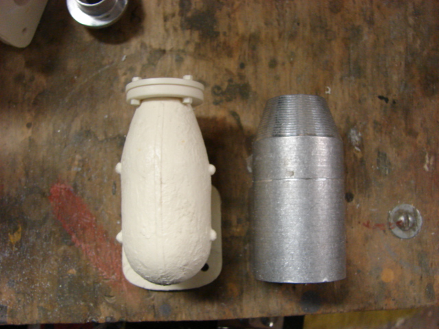
I also machined out of aluminum two pointed caps that I have seen on the real King tiger’s hull. There is only one per side and are both found under one of the bump stops. I will be adding these parts to the product line.
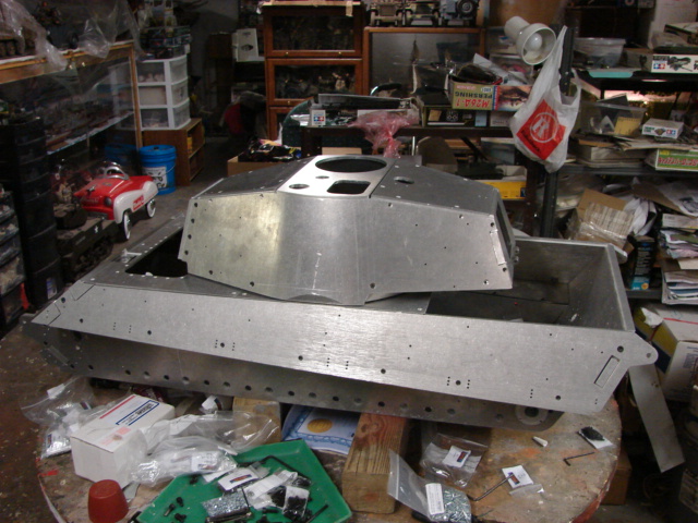
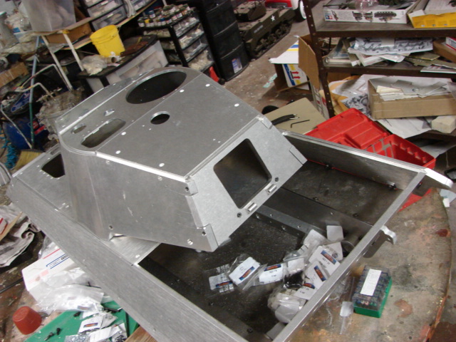
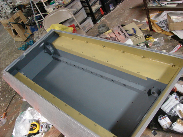
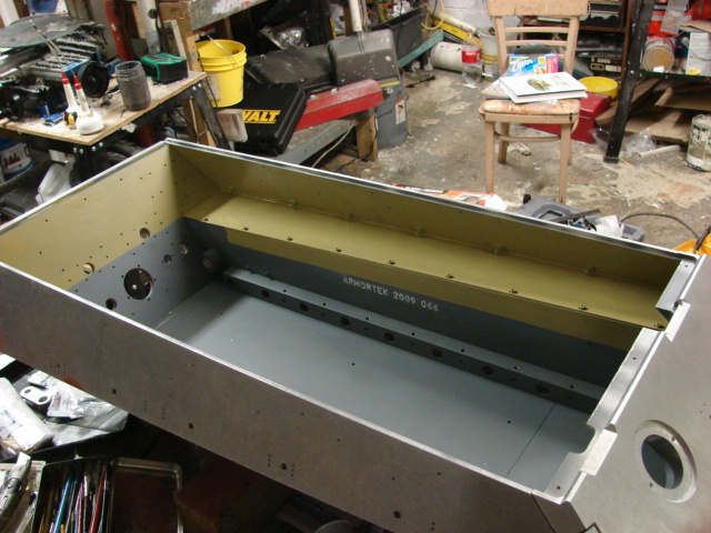
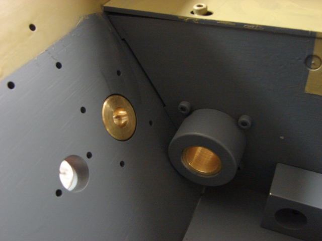
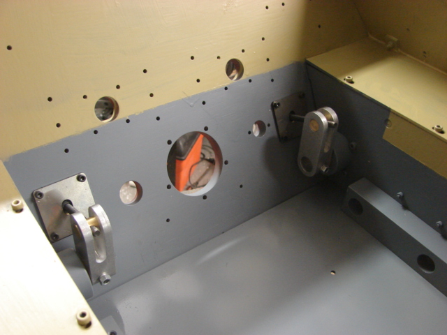
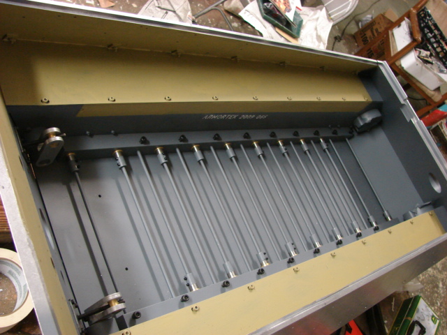
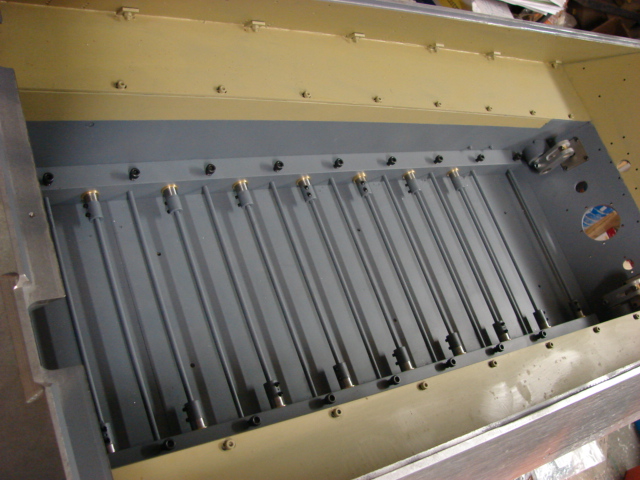
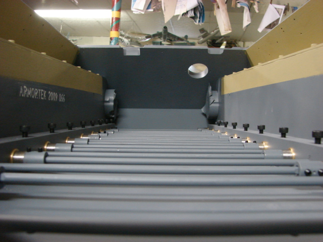
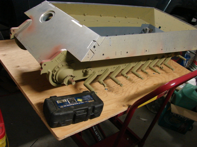
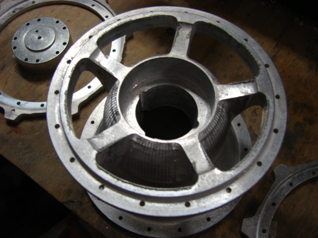
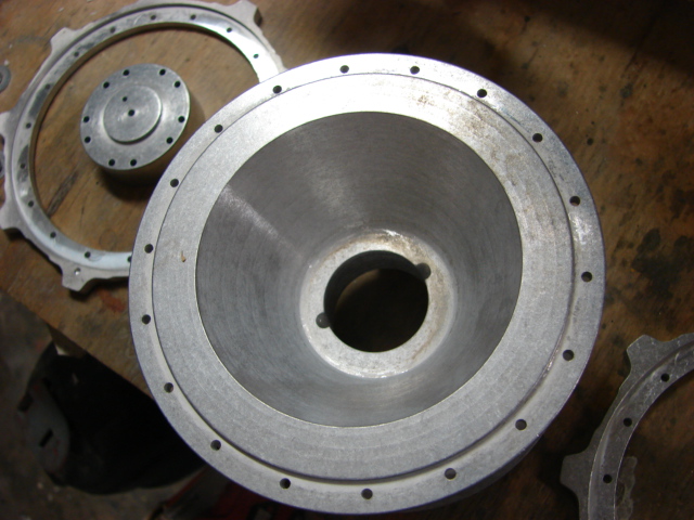
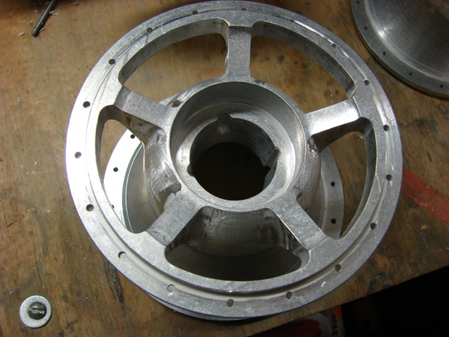
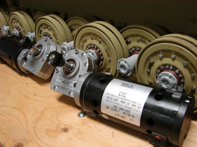
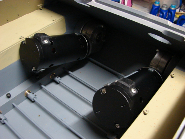
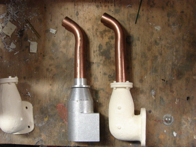
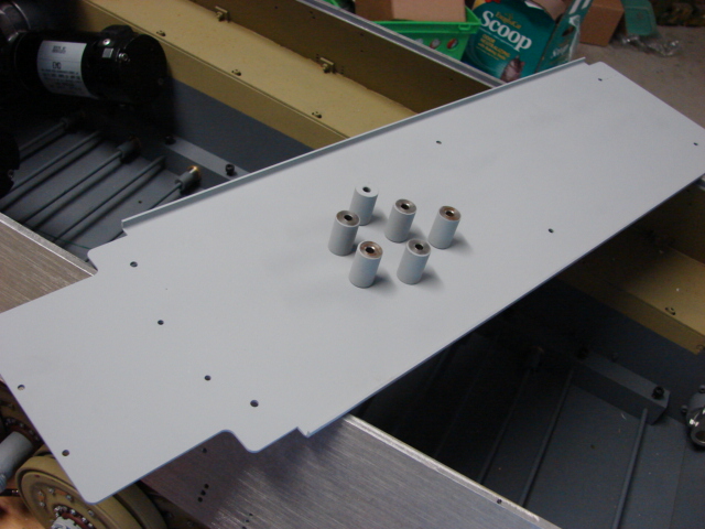
On the tank’s interior I have add the motor mounts. Both motor mounts needed a small amount of material removed for a better fit with the motors.
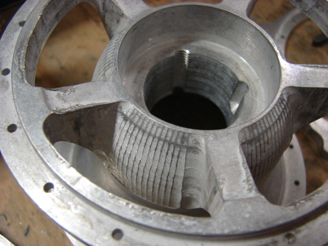
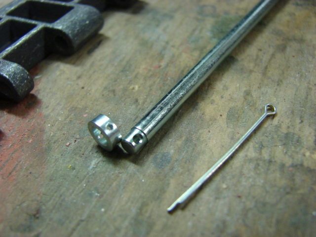
For the left hand motor mount I borrowed Dale’s modification technique and milled in a recess into the motor mount so once fitted I can fit the torsion bar tension screw
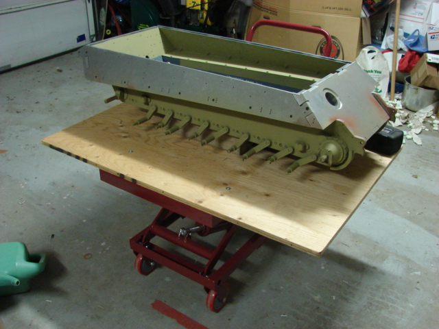
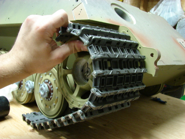
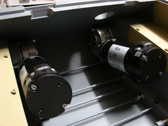
The motors can now be installed.
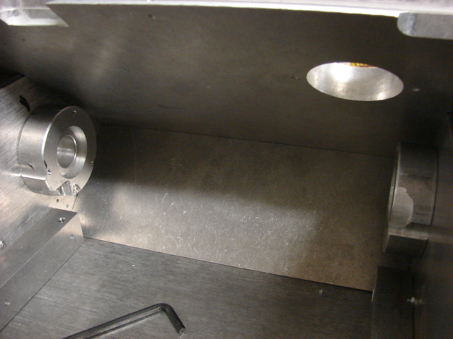
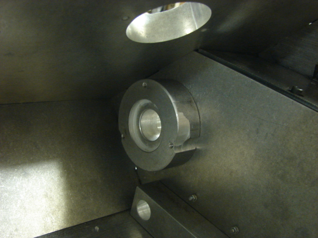
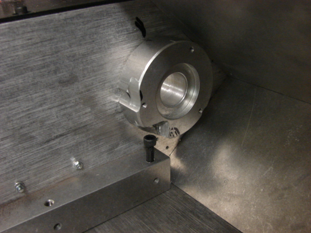
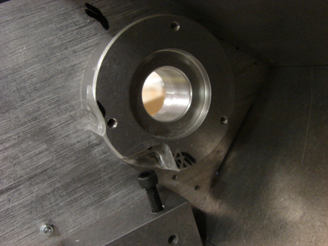
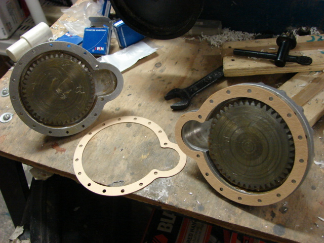
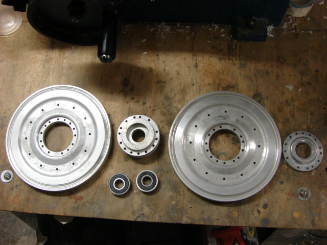
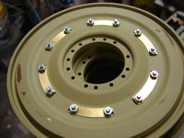
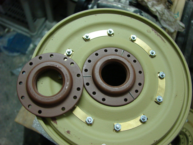
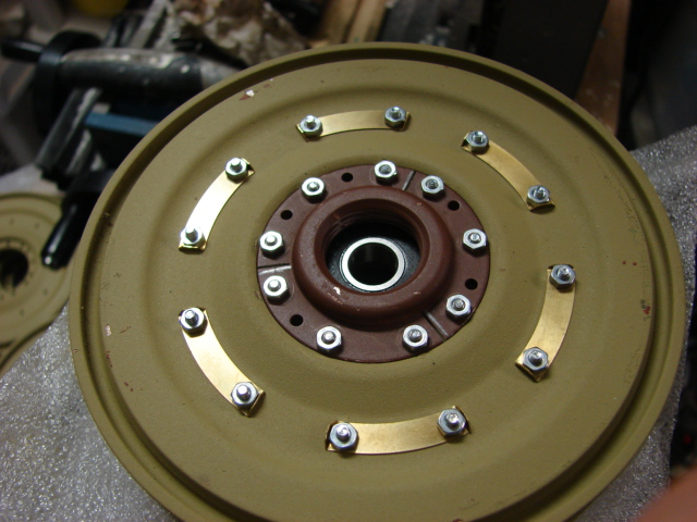
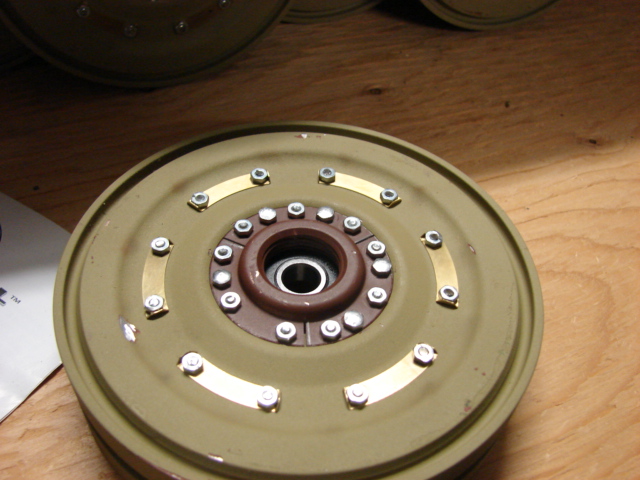
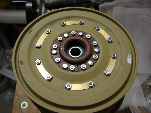
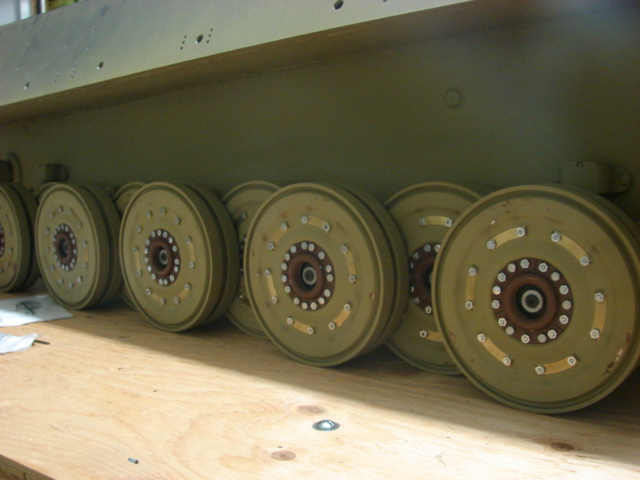
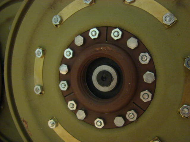
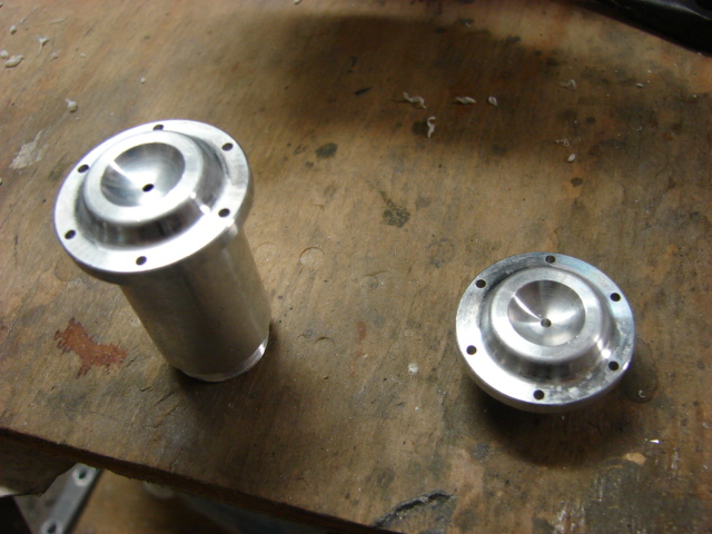
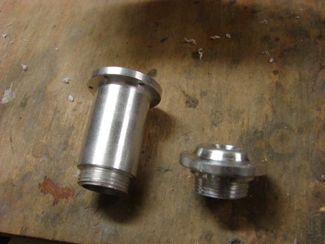
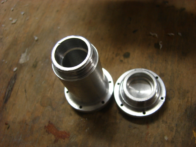
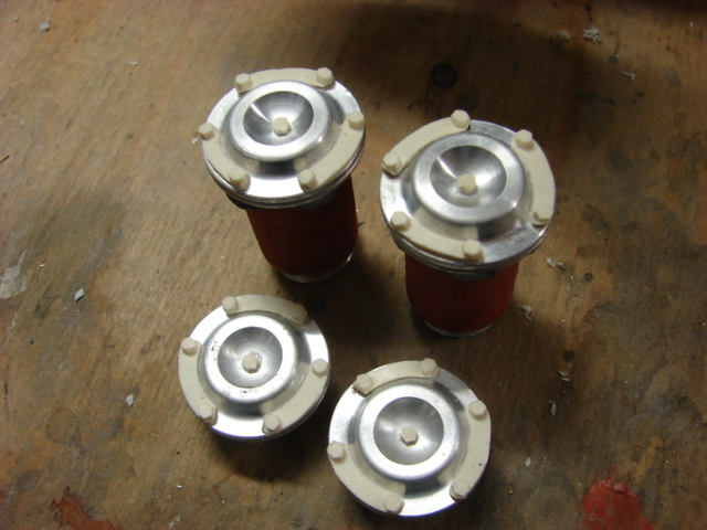
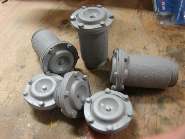
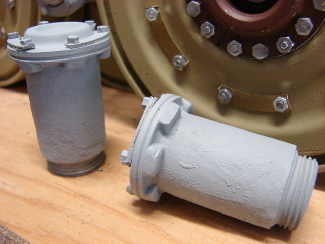
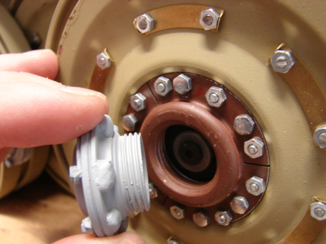
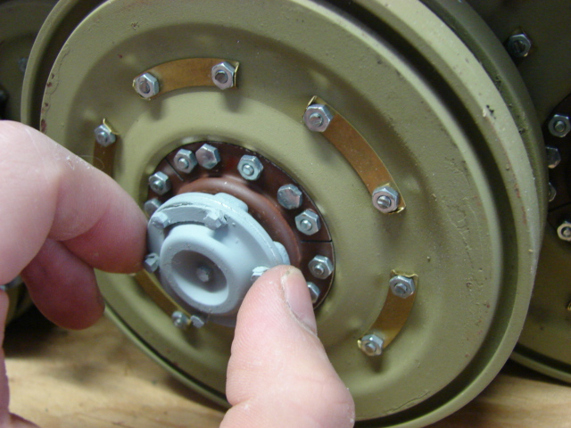
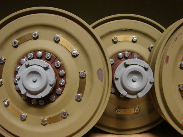
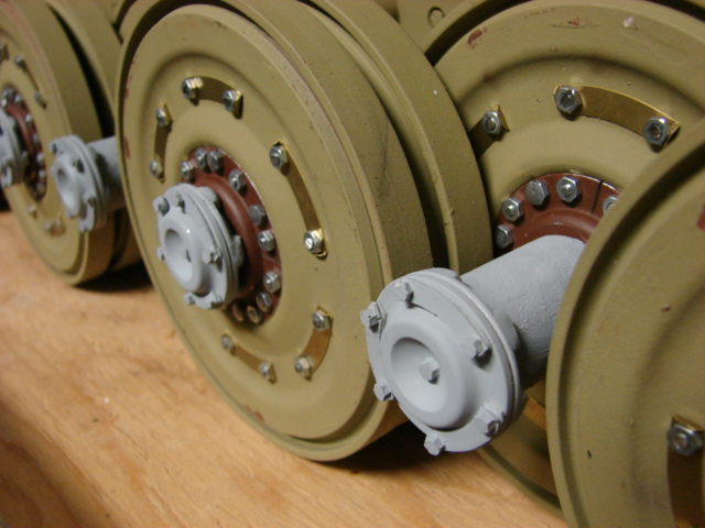
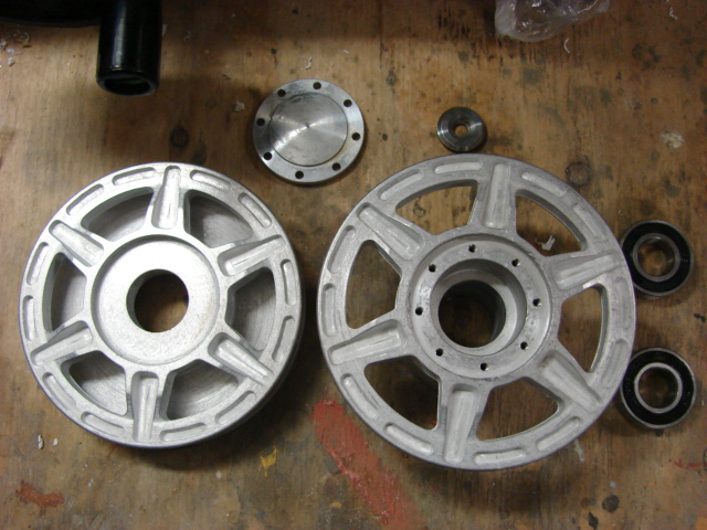
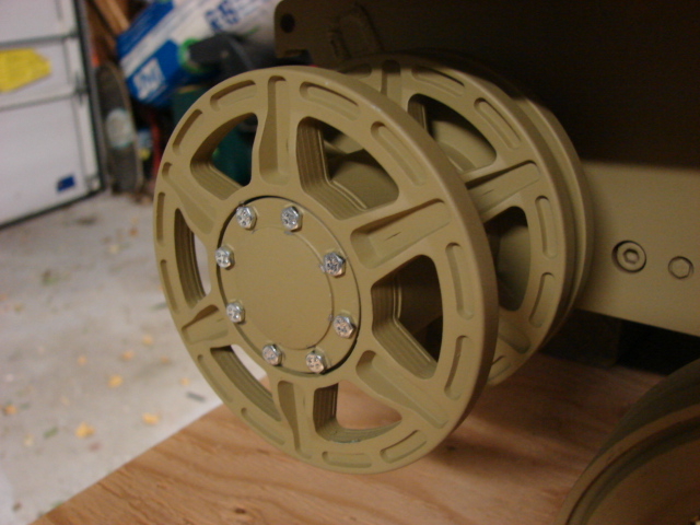
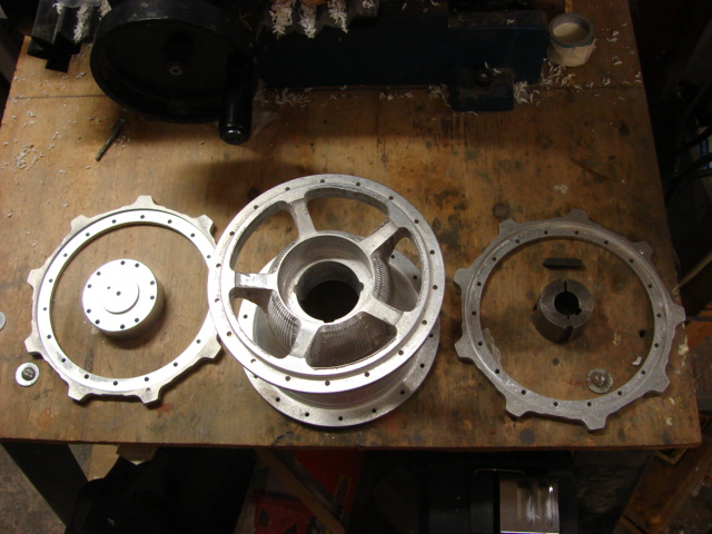
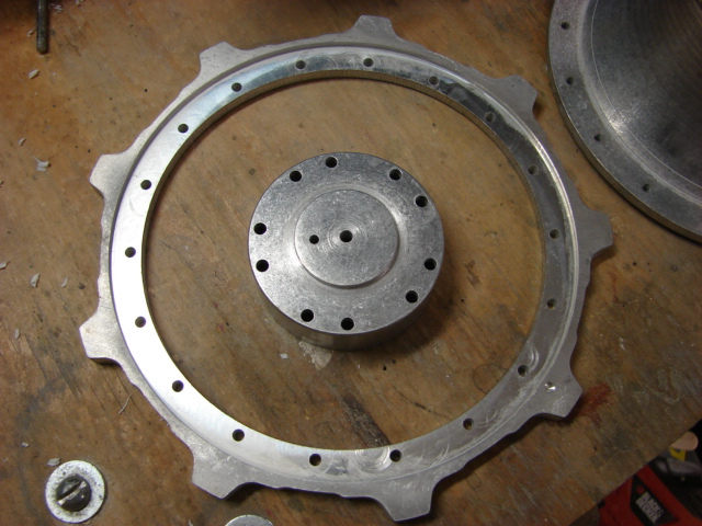
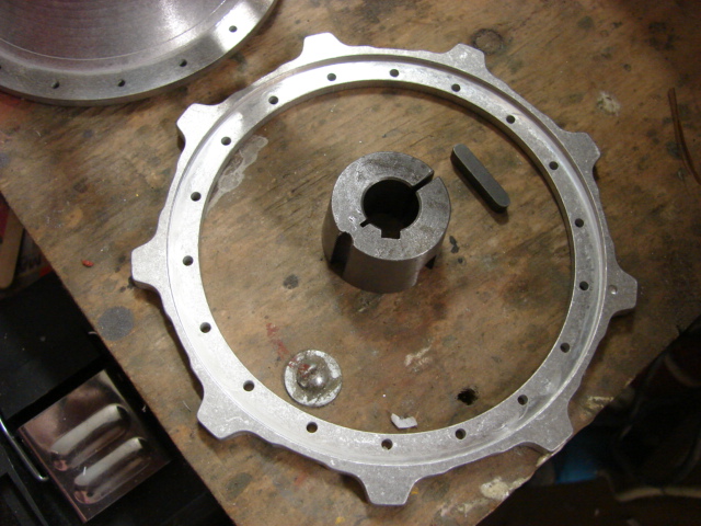
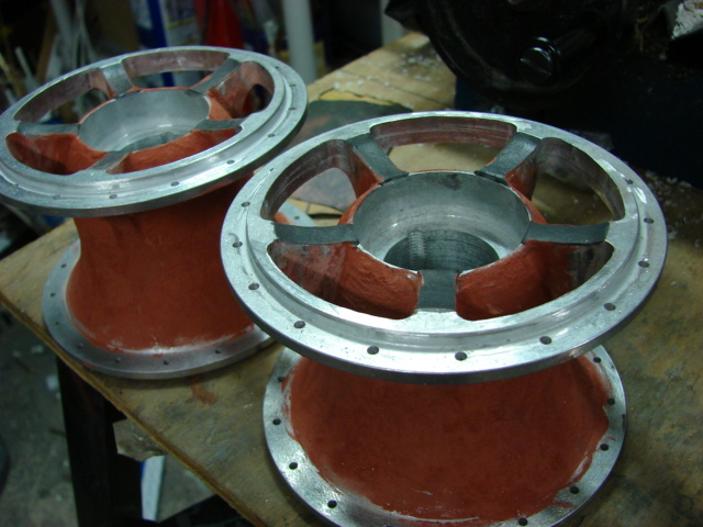
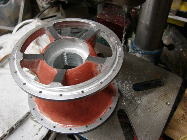
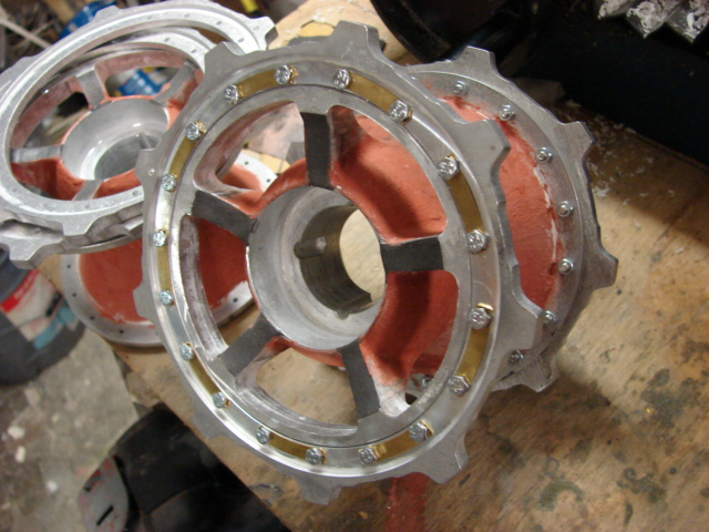
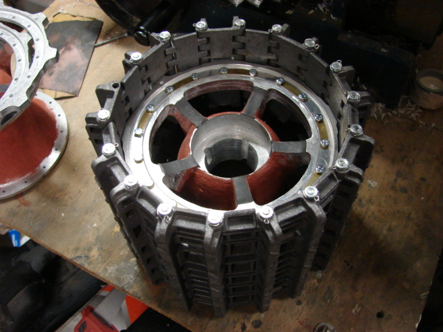
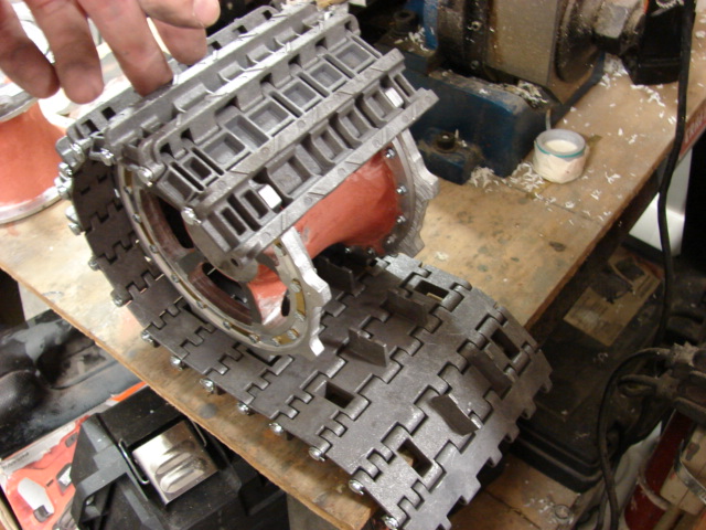
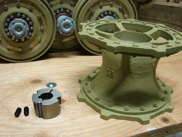
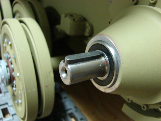
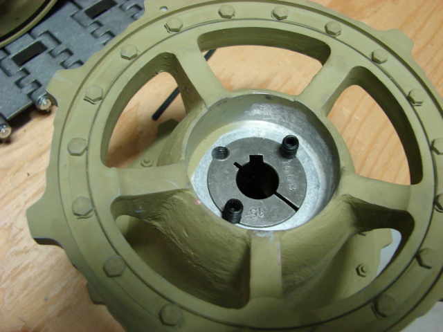
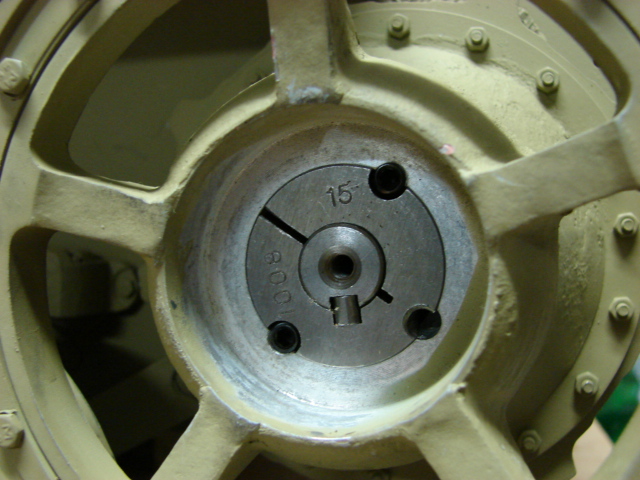
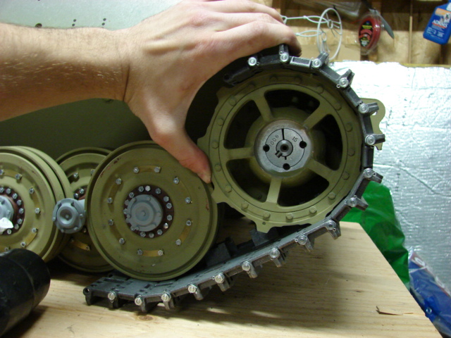
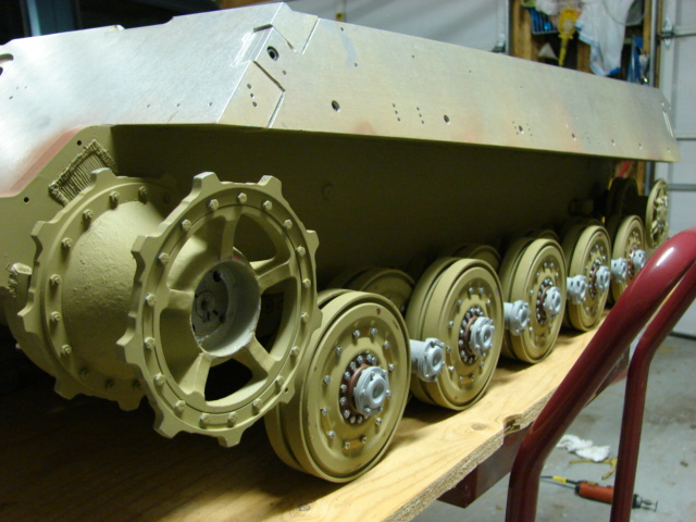
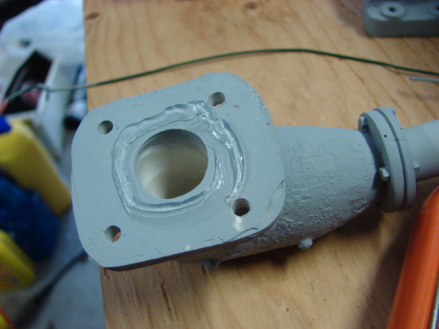
In addition to the motor mounts I have also added the tank’s final drives. The final drives themselves are nicely engineered complete with ball bearings and main drive gears. They were installed as is with no added mods.
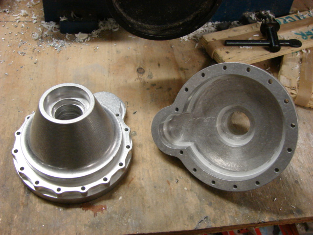
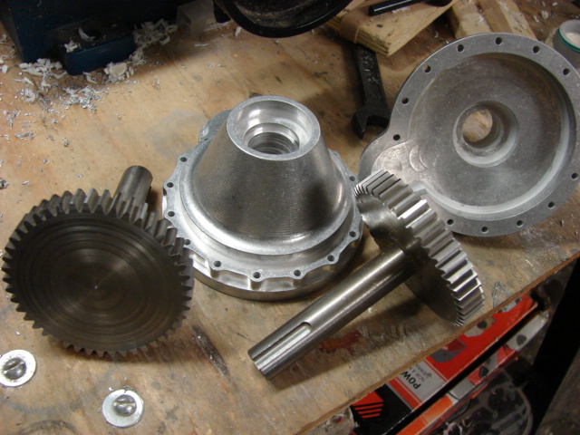
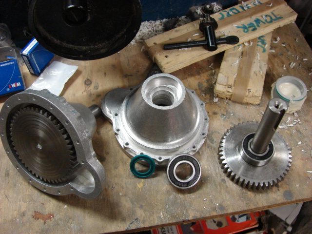
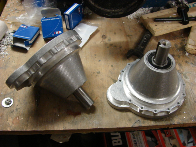
One nice new addition was the gasket. A smear of marine grease and the mounts were added to the tank.
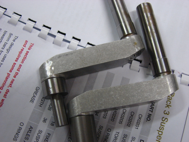
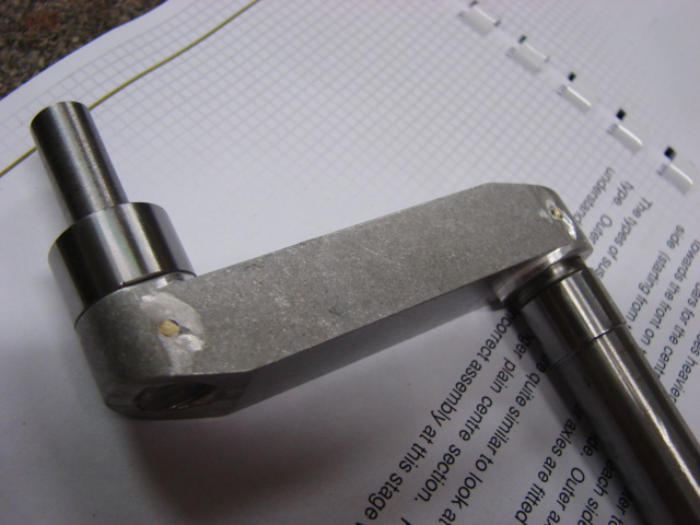
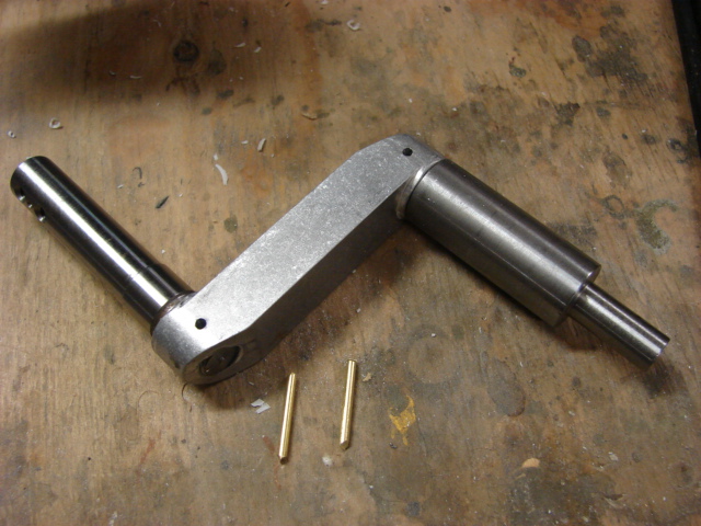
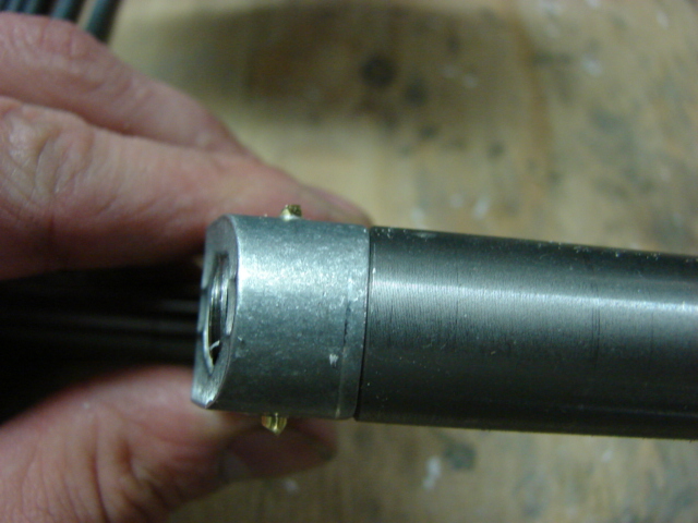
After I complete some body work I will be able to start on the torsion bar suspension.
.JPG)
