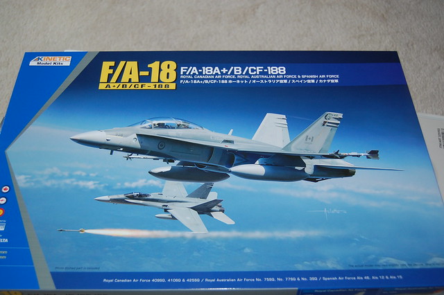
Good morning everyone. I’m building the above noted kit, the newest F-18 kit in 48th scale on the market. I’m not a very speedy builder or anything like that so this WIP will take place over a little bit of time.
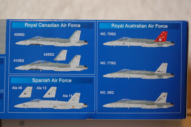
This kit allows you to build a Canadian, Australian or Spanish F-18A, A+ or B model. The box art is nice but you’ll notice that the serial numbers on the RCAF ‘B’ on the box top aren’t the same. Nose shows 938 while the tail shows 934. Hmmm.
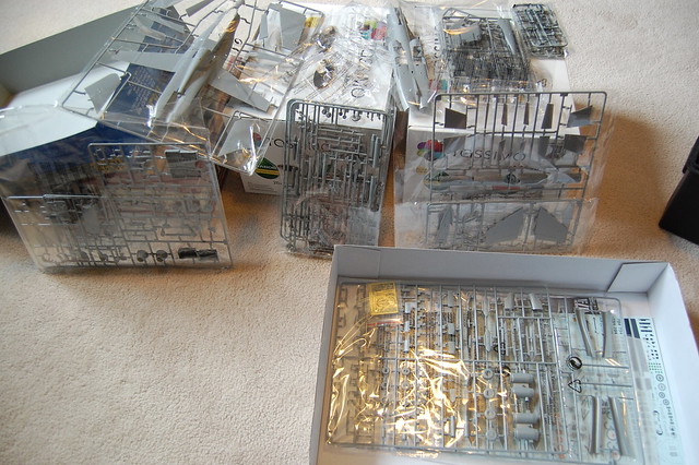
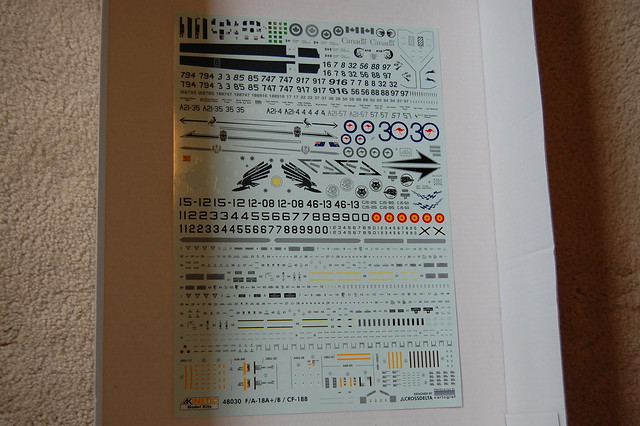
All sprue trees are individually bagged and there is a small photo etch fret. The kit decals look pretty good. I don’t know if the RCAF colours are 100% accurate. I have been informed that the RAAF colours are incorrect. There are decals for all missiles and other underwing stores. For me, the colours are close enough for jazz.
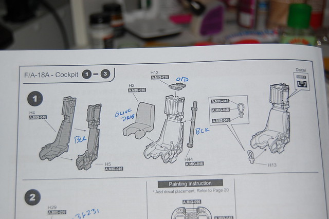
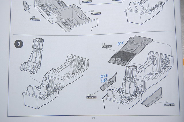
The instruction booklet is good but paint callouts on the step-by-step diagrams are for Ammo of Mig paints. There is a cross reference just before the decal instructions near the back of the booklet. As I progress to each step, I write the colour call outs on the instructions. It helps prevent flipping back and forth.
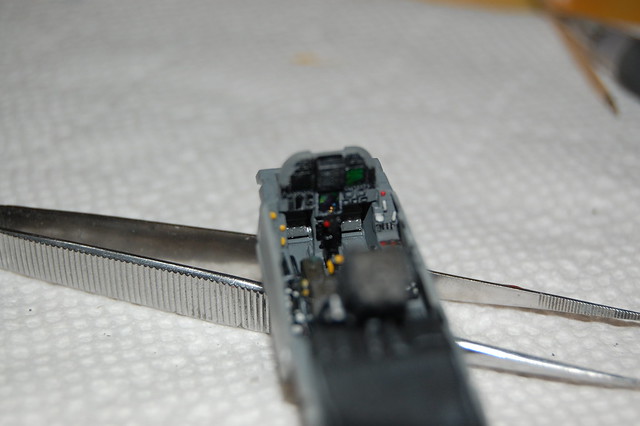
Construction starts with the cockpit, as usual. The tub is for a ‘B’ model. To build an ‘A’, use the blanking plate as illustrated. A word of advice; use a resin seat. It would be much more detailed than the kit seat (go figure!) and there is only one photo etch seat harness supplied on the fret. If you want to build a ‘B’ model, one seat will have a harness while the other will go without. Having said that, nowhere in the instructions does it mention adding the PE harness. One part of the instructions shows the construction of the seat. When it comes time to install the seat in the tub, the seat miraculously has the harness attached. When building up the tub, install the rudder pedals (H15) before the instrument panel (H29). The drawing is a bit ambiguous. All paints, except the seat cushion, are Model Master Enamels. I used Tamiya Khaki Drab for the cushion. The tub is painted FS36231. The seat and blanking plate are flat black and dry brushed with FS36495 (light grey). I gave the tub a wash with very thinly mixed Folk Art craft paint (raided The Boss’s supply!) and water. Switches and knobs were picked out with a tooth pick. I also used prismatic foil for the glass displays on the IP. I like the look instead of decals.
Thanks for looking. I’ll post more photos as progress is made.
So far the cockpit is looking great, really nice work on painting all the controls!
Good luck with the rest of the kit. I’ve been working very slowly on Kinetic’s F-16A/B and it’s… well… interesting.
Up side:
The box is stuffed with ordinance, there’s enough to bomb up about five planes!
The detail looks great!
Down side:
As you pointed out the instructions leave a bit to be desired.
The fit so far has been a bit sloppy. I don’t expect every kit to be Hasegawa/Tamiya quality but this one is almost to the point of a limited run kit like Classic Airframes.
seasick…nice one! Never saw that coming. Well done.
Time for more…
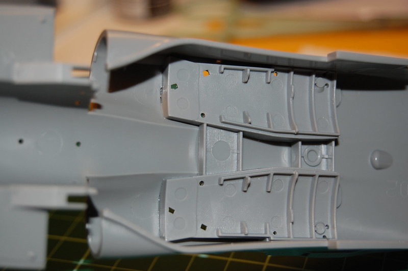
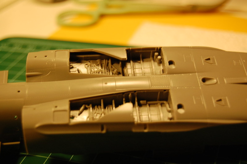
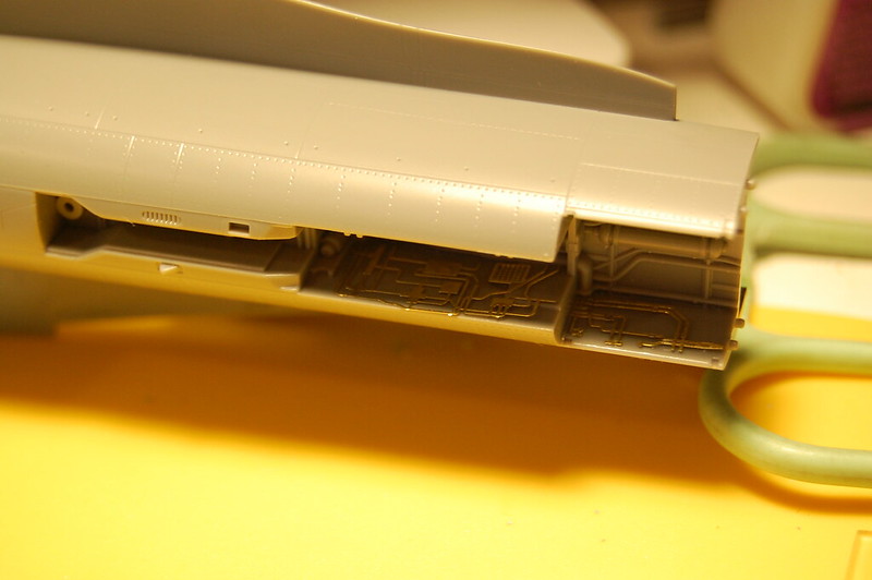
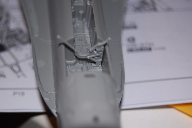
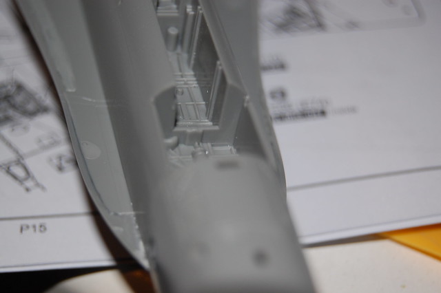
I have made a bit more progress. I’ve glued in the main gear bays. It’s a one piece assembly. I’ll paint and detail later. The intake trunks rest on top of the gear wells.
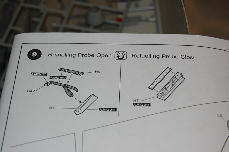
You can build the kit with the refuelling probe extended or retracted. I’m building this one buttoned up. The instructions tell you to glue the door (H6) to the probe well (H7) and then glue the well into the top of the right front fuselage half (C14). Nice, but it won’t fit. To display with the door closed, simply glue H6 to the appropriate area in C14.
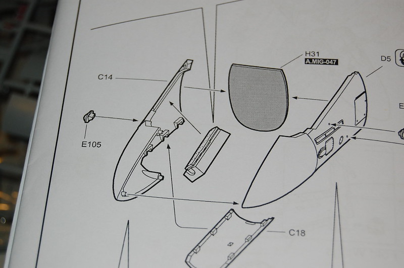
One nice thing about this kit is that it comes with a separate CF-18 left front nose part. No drilling out holes for the searchlight. Very nice.
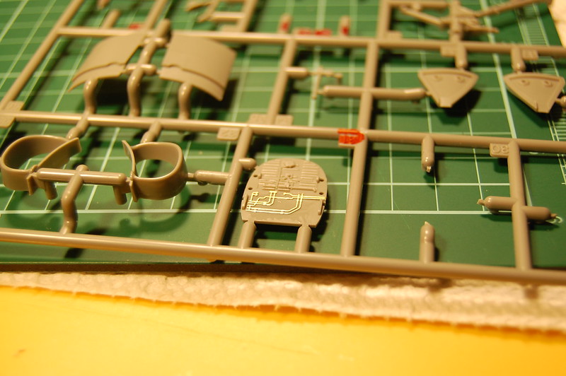
In the instruction page photo above, part H21 is the front nose gear well bulkhead. This is the only mention of this piece in the instructions. There is a photo etch piece that goes on it. Again, nowhere in the instructions does it say anything about adding this PE part.
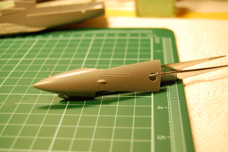
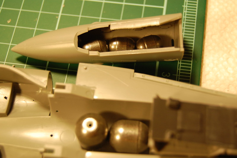
Finally, there’s nothing in the instructions to tell you to add any weight to prevent it from being a tail sitter. I’ve added a bunch of steel fishing weights to the nose (attached with CA glue). I have never had a problem with adding weight in this manner as I avoid lead weights.
Thanks for looking. As usual, comments and constructive criticism are always welcome.
Have you gotten to the point where they specified the left air intake to go on the right side and vice versa? Or did they fix that in the instructions? I tried to build this a while ago and found the instructions confusing and sometimes just flat wrong.
The Canadia version of the F/A-18 was going to be called the “High stick” instead of Hornet.
The Canadian F/A-18 is also has flex-fuel version of the F404 that can run on beer or maple syrup.
On the more serious side micro-mark sells a low melting temperature metal made of bismuth, lead, and cadnium that melts at @170F. Its for ballast for model railroad engines. Its nice and heavy and I pour it in to the randomes on model airplanes and it works real well.
Hi guys. Thanks for the comments and the feedback. So far, I think I prefer the Hasegawa F-18 over this kit. Here’s the latest skinny on this build…
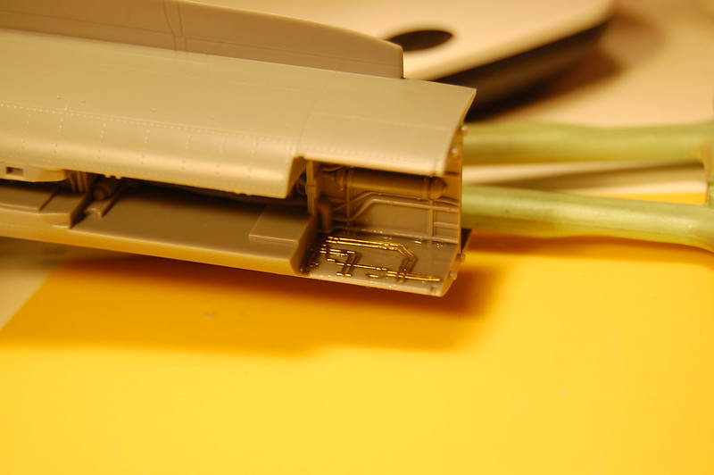
As posted above, I noted that there was no mention of a particular piece of PE going onto part H31. Good reason for that is because it doesn’t go there. Don’t I feel like a mule’s behind. Fortunately, I only attached the piece of PE with Future or Pledge Multi Care Floor Finish or whatever the heck that stuff is called now. It came off very easily. I found out where it goes in the front nose gear bay. It goes here:
There’s another large piece of PE that goes on the flat area at the rear of the bay. There’s no mention of that in the instructions either.
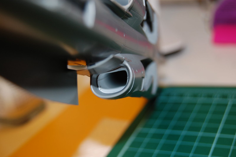
The exhaust nozzles don’t look too bad once you get them painted up and installed. A neat feature is that tabs on the horizontal stabs fit into a slot in the exhaust part. It should prove a nice sturdy point of attachment.
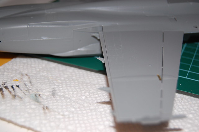
The instructions have you glue the intake trunks into the fuselage before assembling the intakes mouth and splitters, etc. Don’t do it this way. Install the assembled opening, splitters, etc to the fuselage and then glue the trunks in place. You’ll be ablt to line up the trunks much better. The trunks are passable but there is a noticeable seam. If someone does and AM set of seamless trunks…
As per instructions, you see the parts don’t line up well:
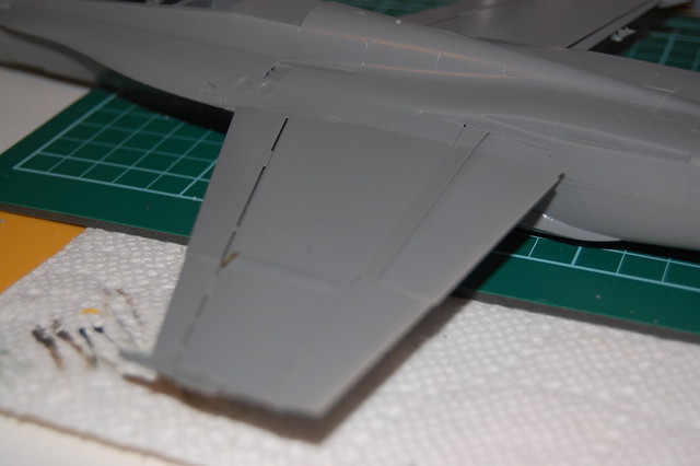
Attaching trunks after assembling outer parts. Still a bit of work to be done:
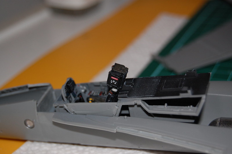
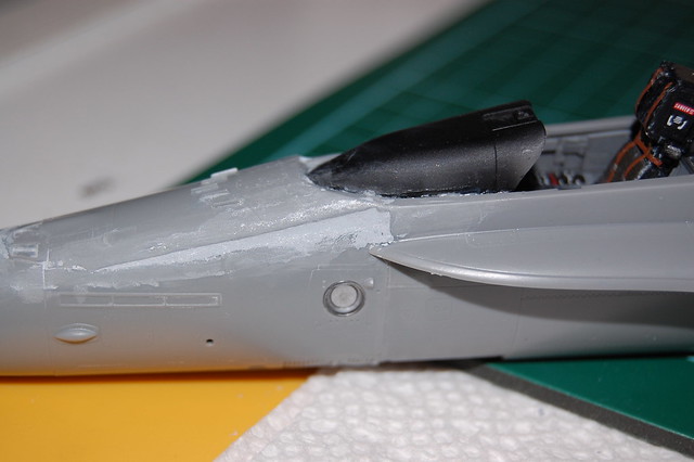
The cockpit tub fits nicely into place. The seat is glued in as I’m finishing the model with the canopy closed.
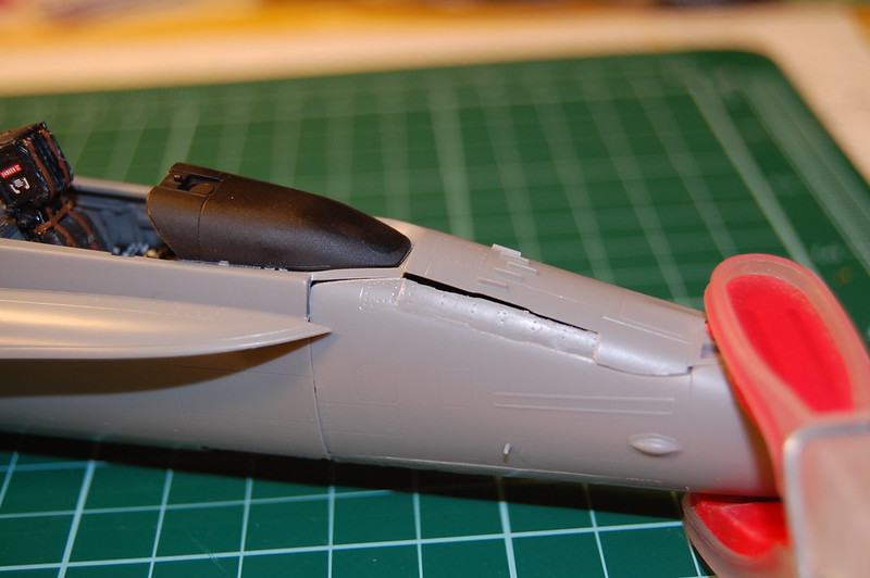
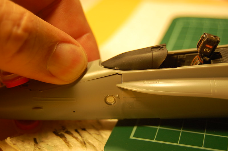
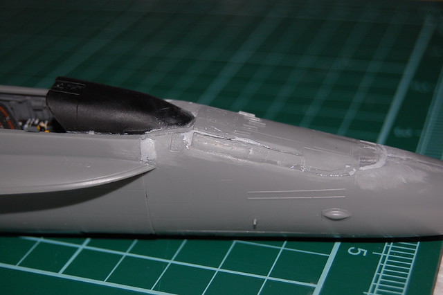
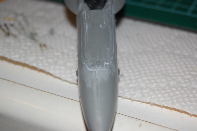
I’m not a big fan of the way Kinetic has designed the upper and lower fuselage join around the cockpit area. Gaps galore. Me holding the parts together:
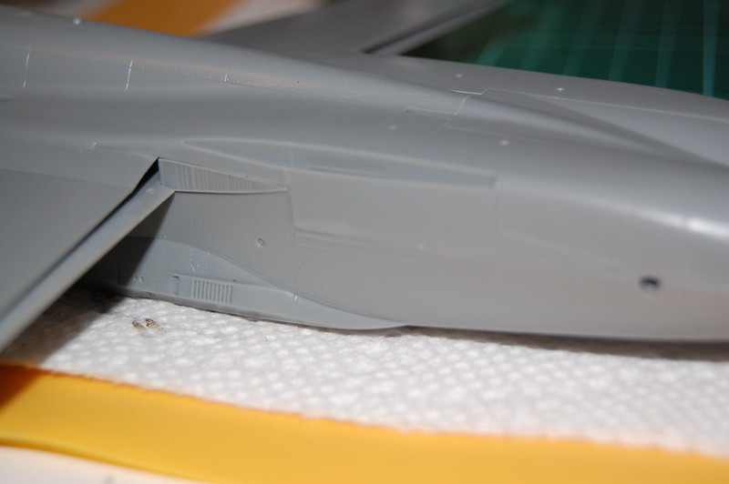
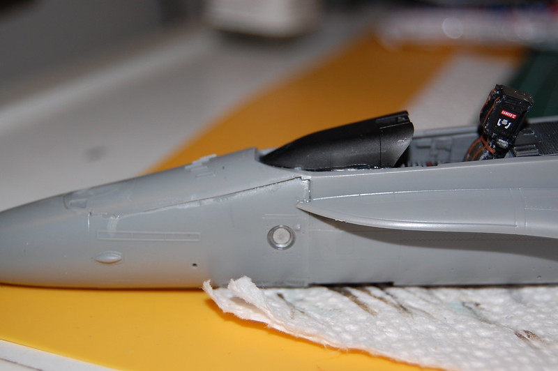
Now glued in place. The rear fuselage join is quite good. The front; not so good. Some work will be required.
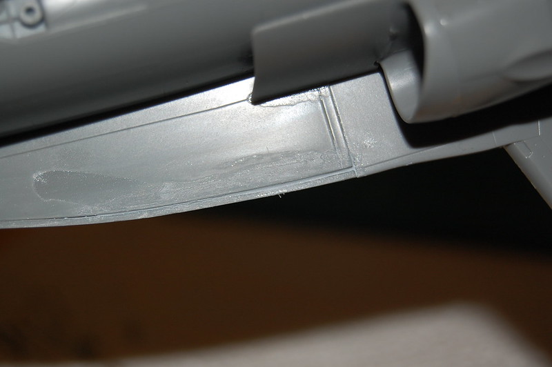
There’s also a gap underneath that needs to be filled.
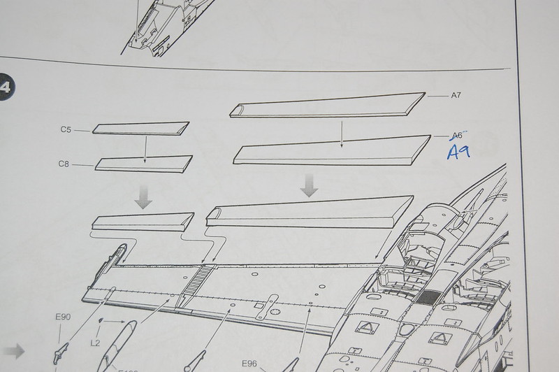
The undersides of the wings glue to the top of the wing / fuselage piece quite well. Be aware that part A9 is mislabeled as A6 . I’m not aware of any other errors like this but this is as far as I’ve gotten.
Thanks for looking folks. As usual, comments and constructive criticism is always welcome.
Thanks for your observations guys. This build has had its ups and downs but nothing a bit of perseverance and elbow grease won’t fix. I have another one in the stash and the issues I have identified with this build should be easy to overcome when I build the second one. Hopefully…
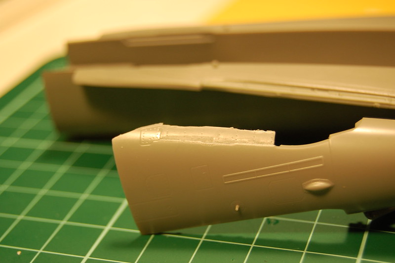
I have made more progress but no photos yet. They’re still on the camera which is in the model room. There was a bit of putty used around the gaps and steps but for the big gap around the refuelling probe door, I applied gap filling CA glue and then applied a bit of putty over it after it had cured. There were multiple filling / sanding / nail polish remover soaked Q-Tip sessions but the putty seems to be quite level. A bit of primer will tell me if more work needs to be done.
As previously noted, I’m doing this one buttoned up; refuelling probe closed, canopy closed, flaps up, speed brake door closed, wings not folded, etc. That lends a few challenges but nothing that can’t be overcome.
Now would be the time to eat some crow. I’ll have mine BBQ’d please. The reason I couldn’t find anything about the PE stuff in the nose wheel bay early in the instructions is because it’s buried in the nose wheel gear / bay assembly section. Again, because I had only attached the PE pieces with Future, they came off easily. I’ll be able to put them in the correct place after all. Don’t I feel like a jack-a$$.
Once I download the photos and make a bit more progress, I’ll post another update.
Thanks Toshi. Today we have a three part update. Part 1:
Some good stuff and some not so good stuff.
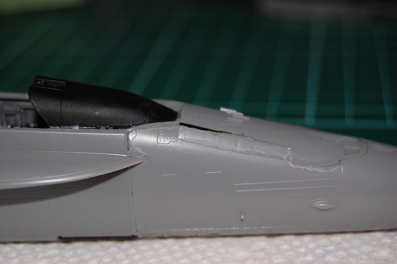
Let’s start with the putty. As stated earlier, CA glue used around major gap on refuel door and then putty over top to smooth things out. Putty only on other fixes.
This kit, like Hasegawa, allows you to build with flaps up or down. I’m going with up. There are two pieces of PE that need to be added to the area at the front of the wing fold. If you build with the wings folded, the PE must be folded.
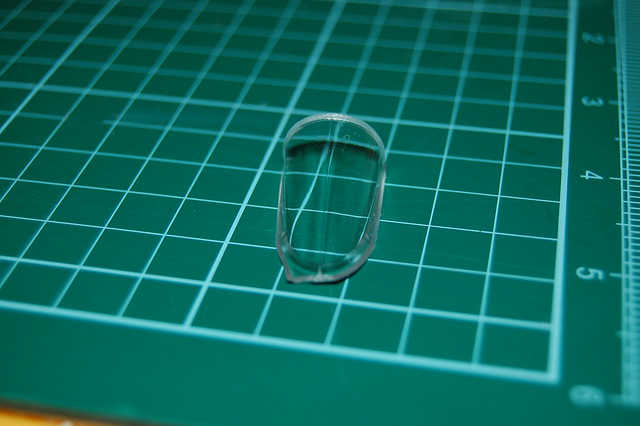
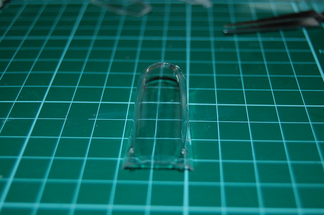
The canopy and windscreen have faint mould seams running down the length. The seam on the front windscreen is the same as that found on the main canopy. The seam was an easy fix. Scraped off excess plastic with the back of a #11 blade and then polished with sanding pads; 3,000 to 12,000 grit and then a dip in Future. Front seam still need to be repaired.
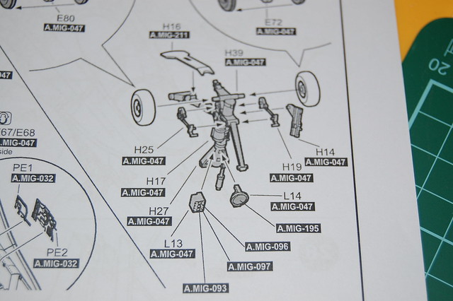
Here are the instructions and the diagram for the front landing gear and PE installation. Roll the dice…and…GO!
In this photo, assembly sequence isn’t clear at all. The gear is designed so the the front wheels may swivel, should you chose to do so. There’s a shaft on part H27 that fits into a slot on part H39 and then part H14 is glued in place to part H39 to allow the swivel. I found this out after I had glued H14 to H39. Furtunately that TECT hadn’t cured so I pried the two pieces apart and put the shaft of H27 into the slot where it belonged. Mine will not swivel and I’m okay with that. The rest of the parts fit together well. I attached clear parts L13 and L14 with CA glue. I painted the back of the landing light silver to present the illusion of the dish of the light after everything has been painted white. L14 is a single piece where Hasegawa’s F-18 has a dish and separate lens.
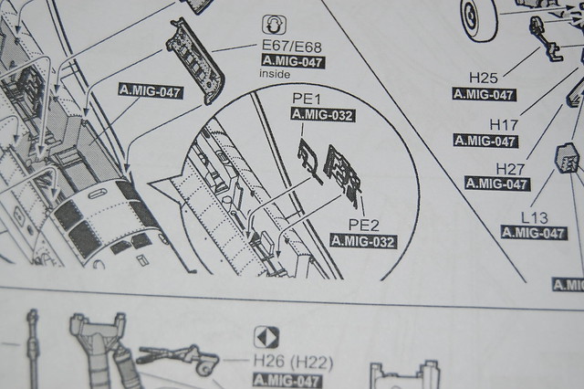
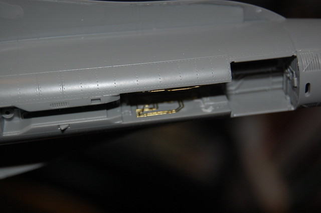
Here you can see were the nose well PE parts go. One part goes on the right side and the other on the left side of the well walls. I’ve gotten to the point that even if this isn’t right, I don’t care. They’re in and that’s where they’re staying. They don’t interfere with the main gear assembly of the door actuator piece.
Further, where does part F13 sit in the nose gear well? Here it is, placed in the well. The instructions are vague and show it placed further to the left (as viewing the instructions) than it should be. It fits into a small recess on the roof of the bay.