1:48 Battleship New Jersey Animated Steering Gear Model Start-to-Finish Build

If any of you read my Engine Room thread, you’ll remember that I started talking about the next model for the Battleship New Jersey Museum & Memorial; the Steering Gear System including the Rudder. When I delivered the Engine Room to the Ship las December, my nephew and I took many pictures of this space. And like the engine rorom project, the success of the project was predicated on obtaining accurate engineering drawings on which to base the model. John Miano, that wonder fellow who sent me the engine rooms drawings has done it again. Last night I got the drawings needed to start the project. He had already sent me a few including detail drawings of the inboard propeller, but I needed much more.

I now have the complete set of profiles for the rudder. The rudder—which I thought was a gigantic casting when I saw the ship in dry dock—is built like an airplane wing with formers and a welded skin. There is a very large hub forging that is the rudder mounting component. I plan on building the rudder as it in the 1:1 world with some part cutaway to show how it’s constructed.

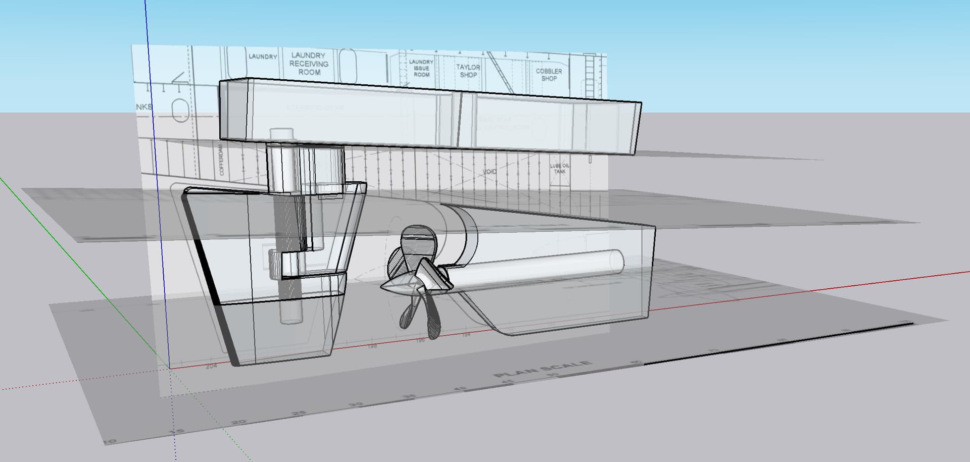
John originally sent drawings he made of the constructed rudder. And then today he sent the entire set of formers and castings that make up the rudder, plus a nicely dimensioned drawing of the steering system. While there as dimensions missing—mainly those concerned with the equipment sizes themselves—there are enough meausurements of the overall siting and foundation that I can scale the rest nicely in SketchUp.

Before these drawings arrived, he did send me accurate drawings of the 17’ 6", 5-bladed inboard prop. I’m only modeling the starboard side. The port side is essentially identical except for one strange aspect. The starboard side machinery is located off the ship’s axis to the aft, whereas the port side is parallel to the centerline. Otherwise, they’re the same. They are not mirror images. They are identical. I originally thought I could model the ship next to a mirror, but the reversed image wouldn’t be correct.

This is what I created with just the propeller drawing and plans that I previously used in the engine room project. All those square edges on the prop will be hand-finished after 3D printing. The geometry is correct. I was mainly concerned at that time if the parts could fit on my printer. They can in 1:48.
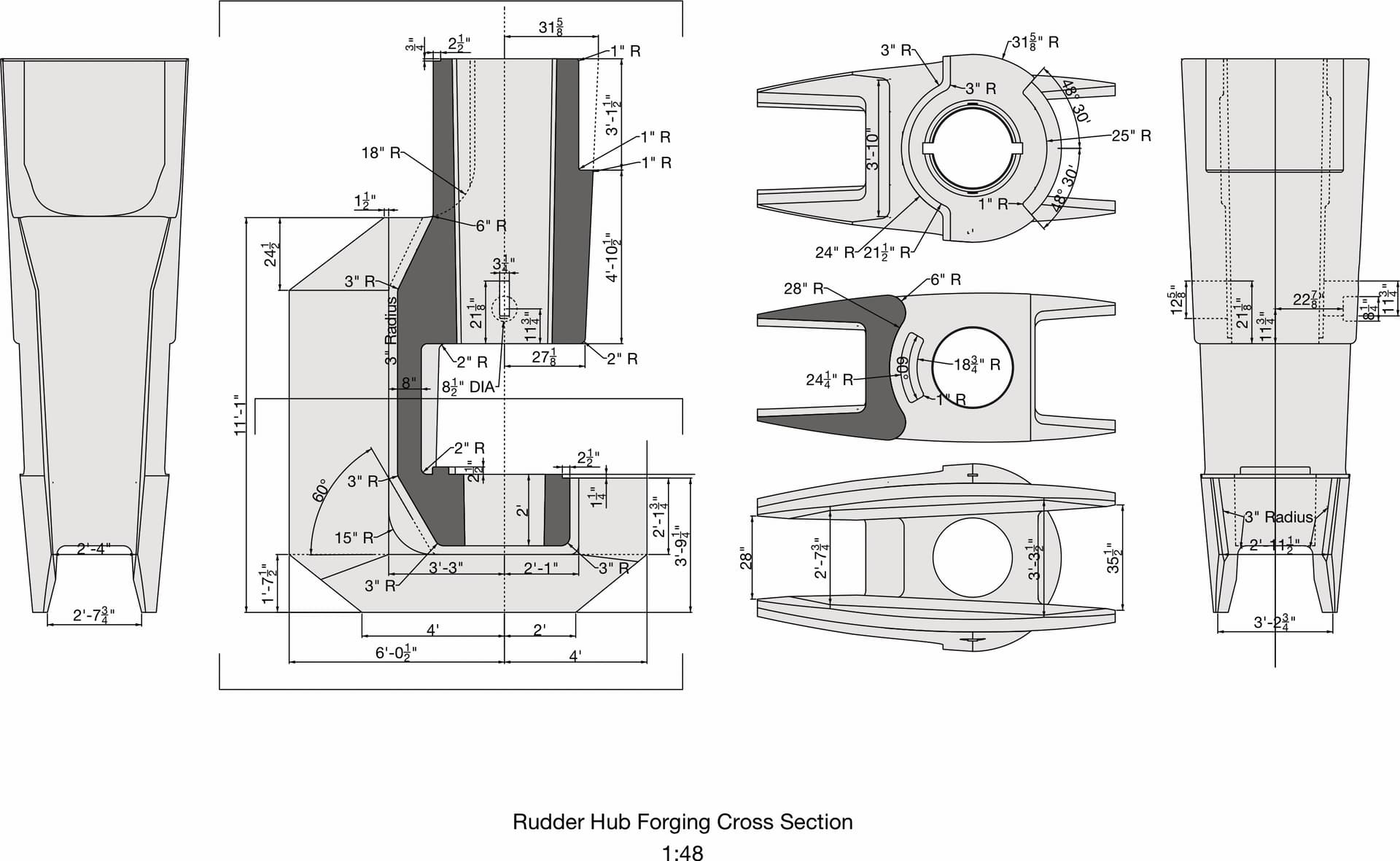
Here are some of detail drawings of the rudder assembly. I’m noodling how to create the rudder. If I made it out of styrene, I can cut all the rib profiless on my Silhouette vinyl cutter. It can’t cut through the styrene, but it can accurately scored for snapping or cutting with a knife. It could also be constructed out of ply ribs and balsa skinning a la a model airplane wing. I’m not sure how the cutter would work with ply, but it could work with balsa ribs. It will be time for experimentation. The rudder is essentially an airfoil the creates pressure differentials that help in creating steering pressure. The central hub is a fabricated part out of forgings and that would be 3D printed.
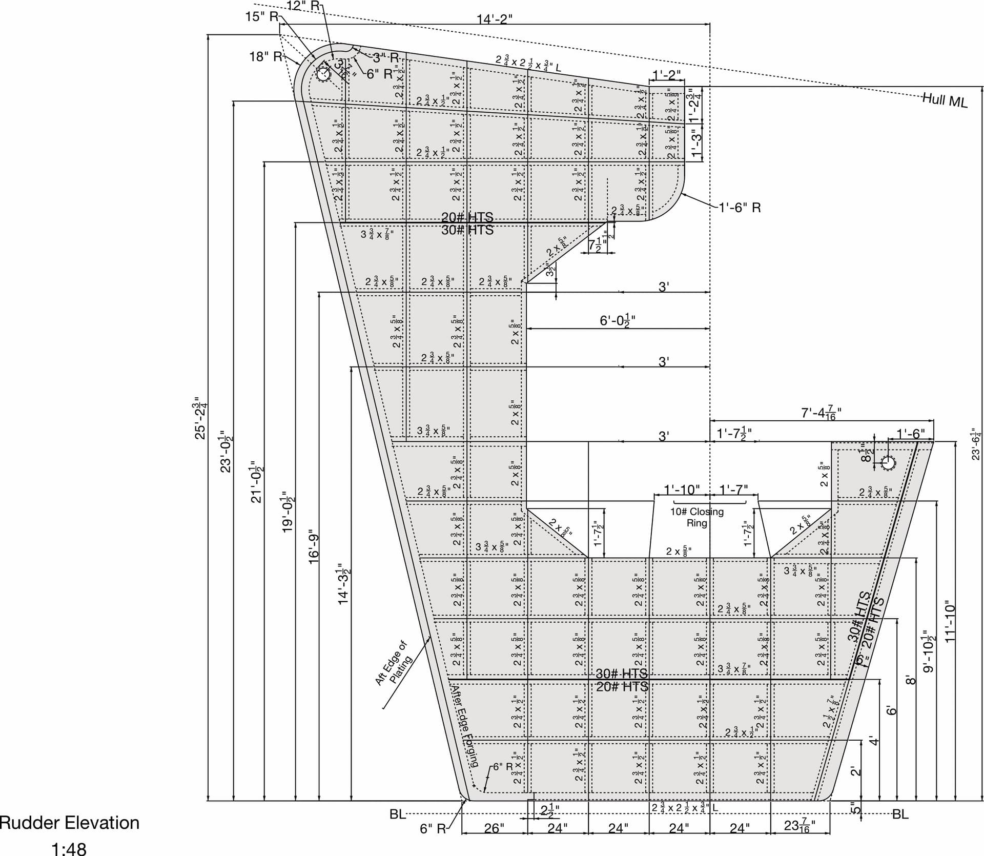
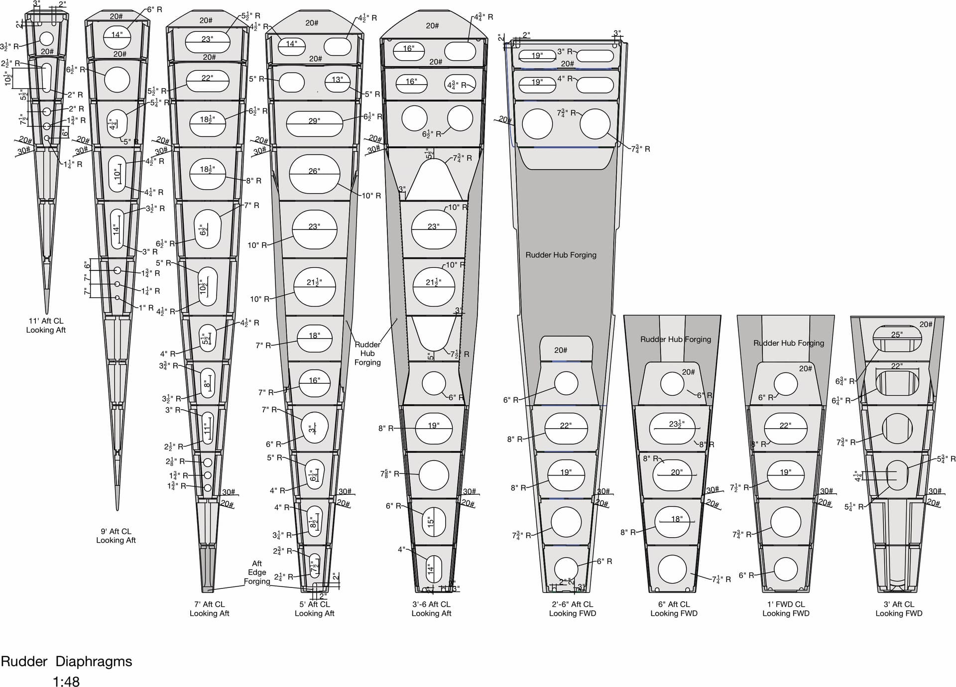
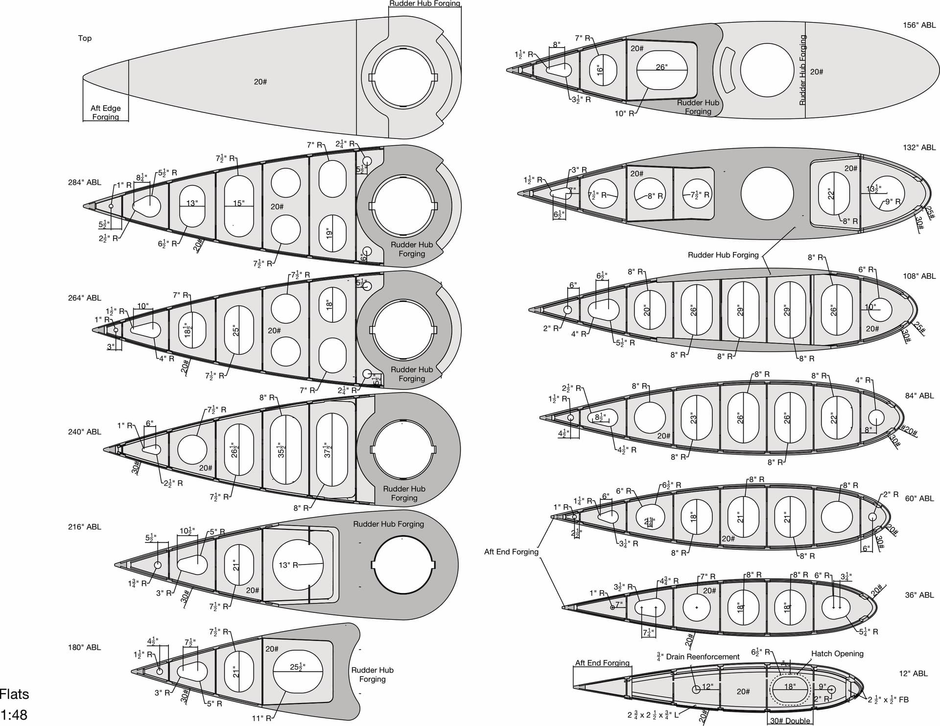
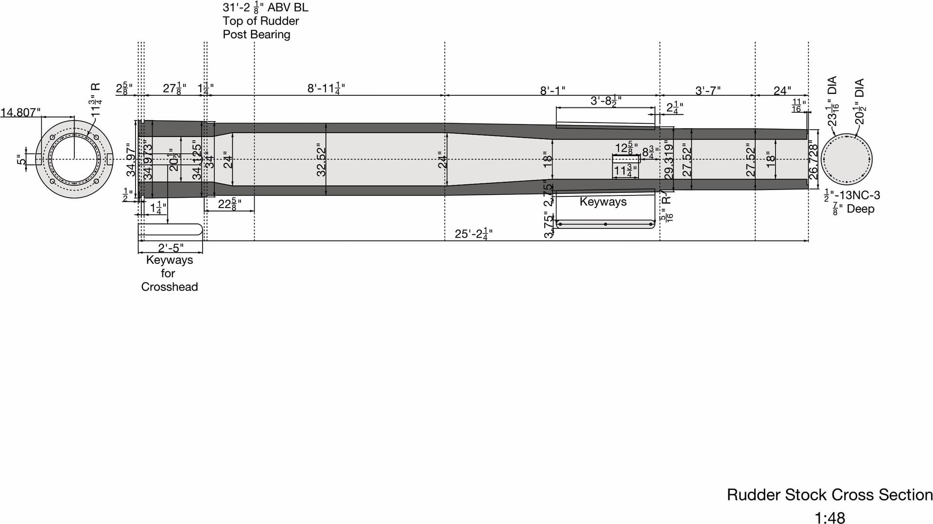

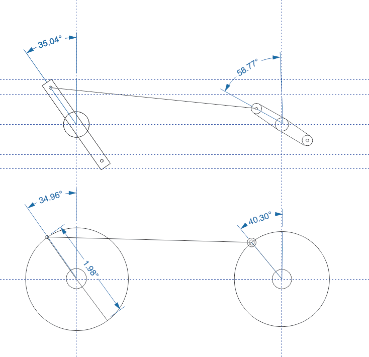
And here’s the main drawing.
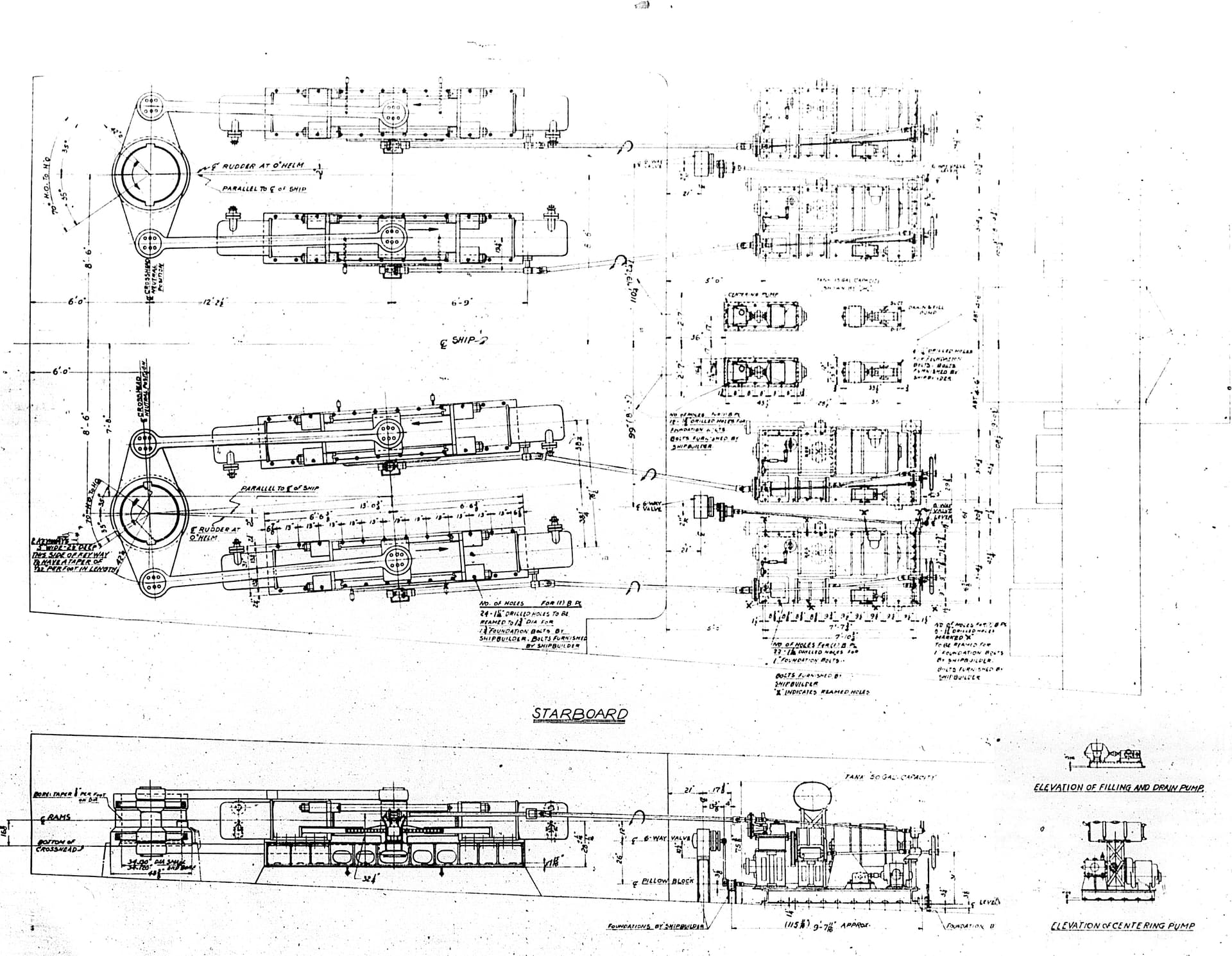
Notice the different in angle of the starboard (bottom) and port side machines, and notice on the elevation drawing that the floor is not level in that part of the ship and the foundation accounts for that and levels it out.

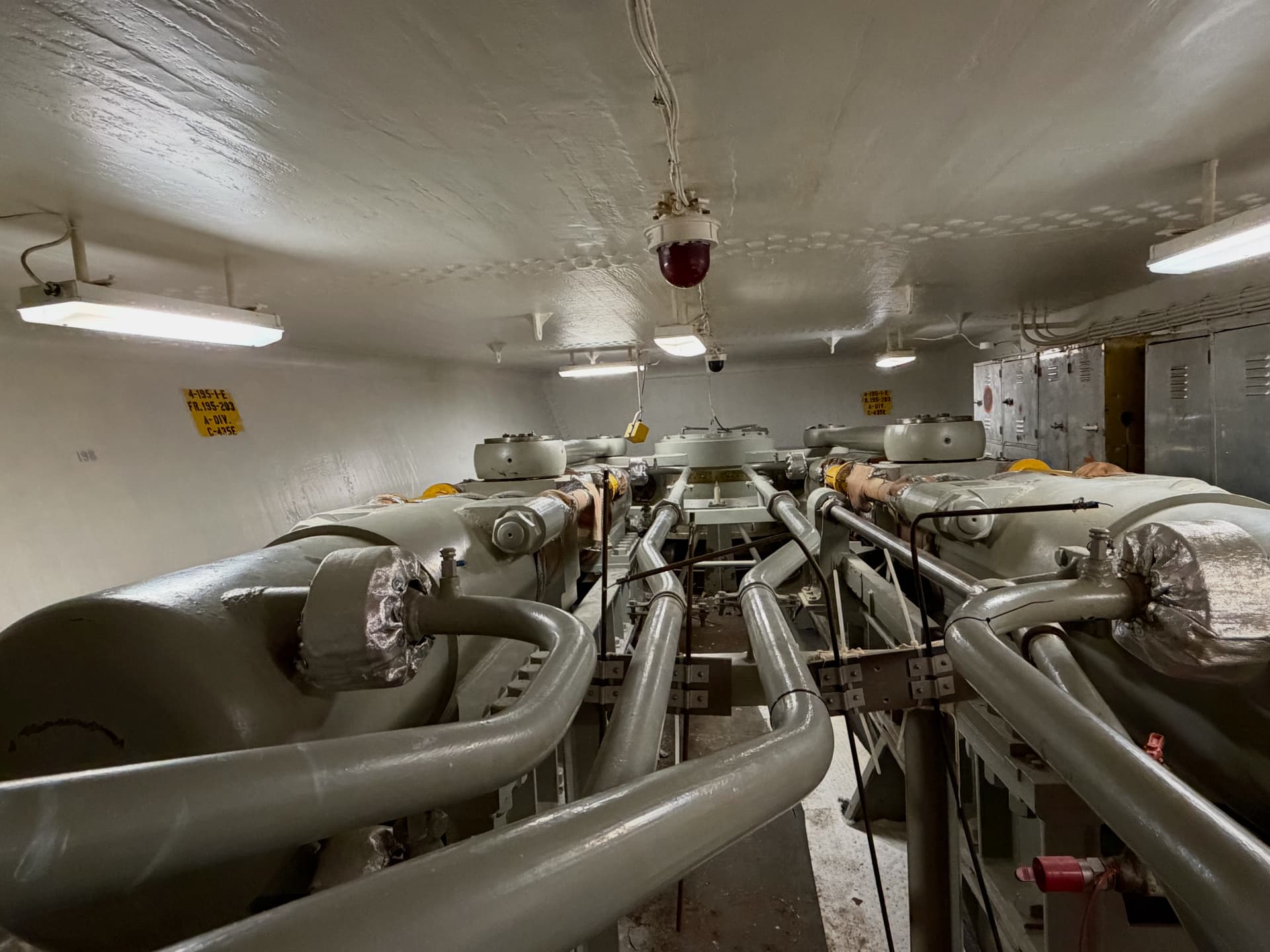
This is what the machine looks like for real.
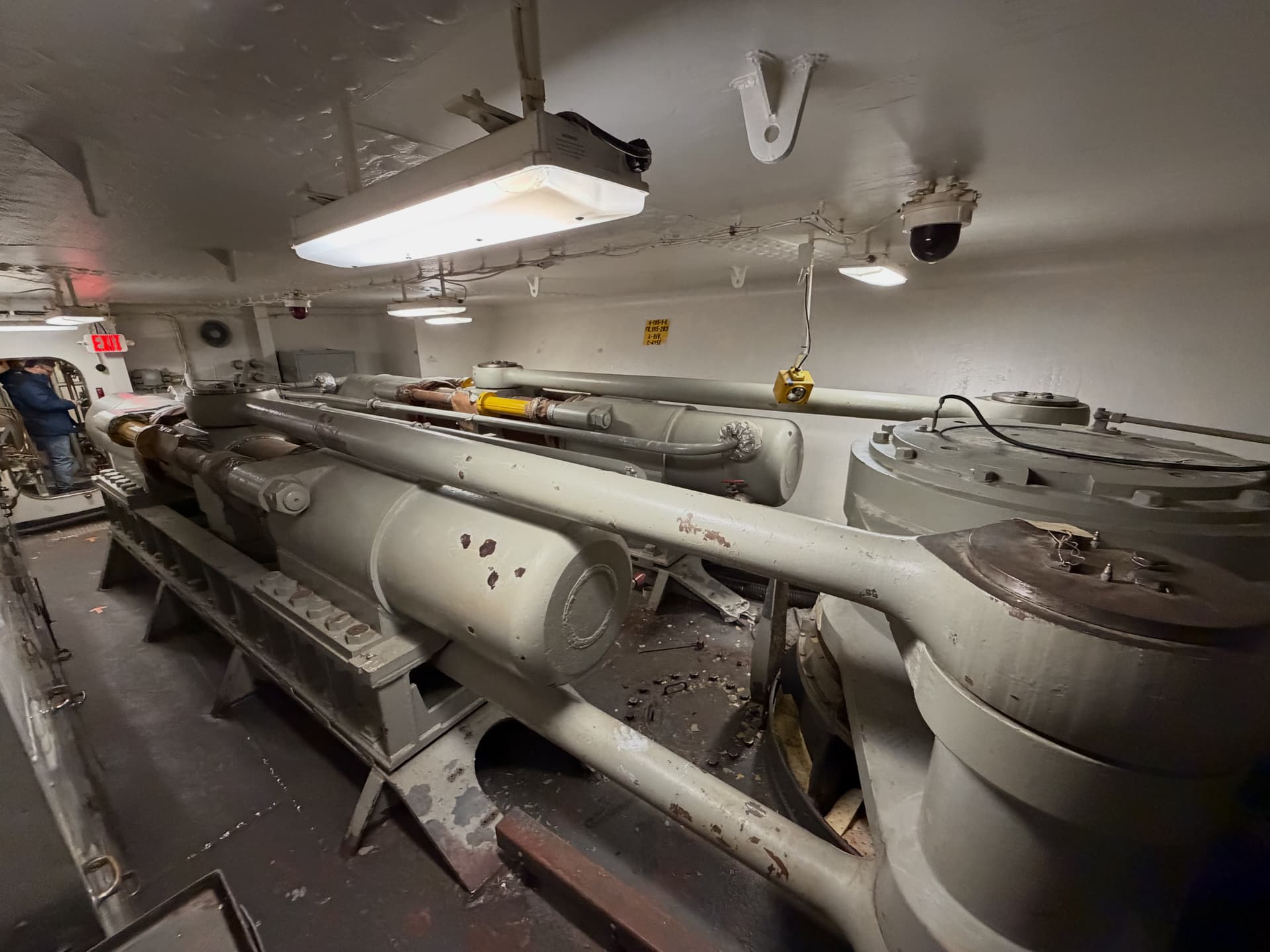

All the exterior walls are armored. The partition wall is not. The armored side walls are angled away at the top following a similar scheme as with the main armor. However, unlike the main armor, this is a structural part of the space. You can see the scalloped weld straps at the bottom edges.

With the drawings and hundreds of images I made during my December visit to ship, I believe I can do a respectable job. I still need some framing drawings from John Miano with the goal to frame that area of the ship as I did under the engine room. It’s more complicated in the aft due to the compound angularity of everything.

For animation I’m going to use a heavy duty RC servo driven by an Arduion MicroController. I don’t know how to program these clever devices and was starting to look at YouTube tutorials. Then one of my genius grandkids suggested to just ask ChatGPT to write the program setting out the parameters I want it to meet. I want the rudder and machinery to turn to port 35º wait a 10 seconds, return to center wait 10 seconds, turn to starboard 35º and back to center and pause for a minute and then repeat.

It produced a perfect program in about 2 seconds including what terminals to connect the servo to on the Arfuino and offered to provide more instruction if you need it. It was my first application of AI and it was pretty darn good. There’s no reason I have to learn a programming language for an application I probably only going to use once.

I also am developing a walkthrough movie of the engine room based on photo realistically rendered screen prints of moving through the model describing the machinery and their functions. After writing it and getting Ryan Szimanski’s go ahead, I wasn’t happy about me narrating. So I sent the script to ChatGPT, and instructed to just one paragraph aloud as a test. I also told it what kind of voice I wanted and what the end use was for. I wanted something like Gregory Speak… i.e. deep and authoritative. It read it perfectly.

Now I have to be able to capture the audio output of my laptop for input to the movie soundtrack. My genius daughter-in-law had a solution for that in an app that captures audio on screen in a Mac. I’m all set to produce a perfectly narrated soundtrack for the program. It will be put up on YouTube and played on the monitor near the model in the ship.

Say what you will, this tech is astounding, and I’m not afraid to apply it.
5 Likes

The level of detail and planning in each of your projects is insane.
You sir, are a scratch building master.

1 Like

this should be good ,

1 Like

1/48, now you’re talking!

1 Like

Actually, I’m thinking bigger!

Started some premliminary design work. My first decision is 1:48 is probably going to be too small for the operating features to be robust enough for museum usage, and the model is smaller than the others and can be done in a larger scale on my equipment. Since I’m not going to 3D print the largest part (the rudder) and build it like an RC model aircraft. I just did a check witrh the prop and it will fit on my 3D printer at 1:32. The model will be about 20" long at that scale with is doable.

The ram links have fillets where the shaft portion reaches the hub. I need some help in drawing that since they’re following a curved surface, so FOLLOW ME won’t work. I think I need DaveR’s help on this one.

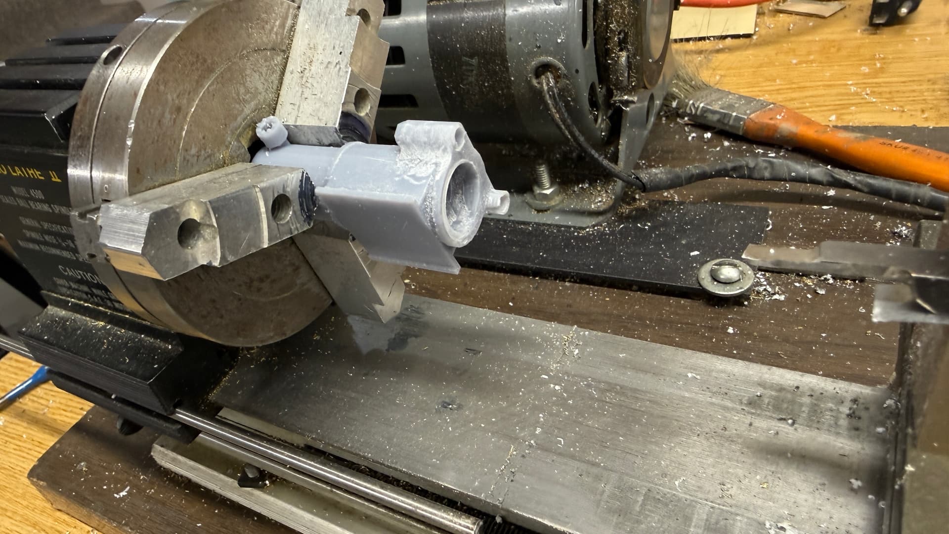
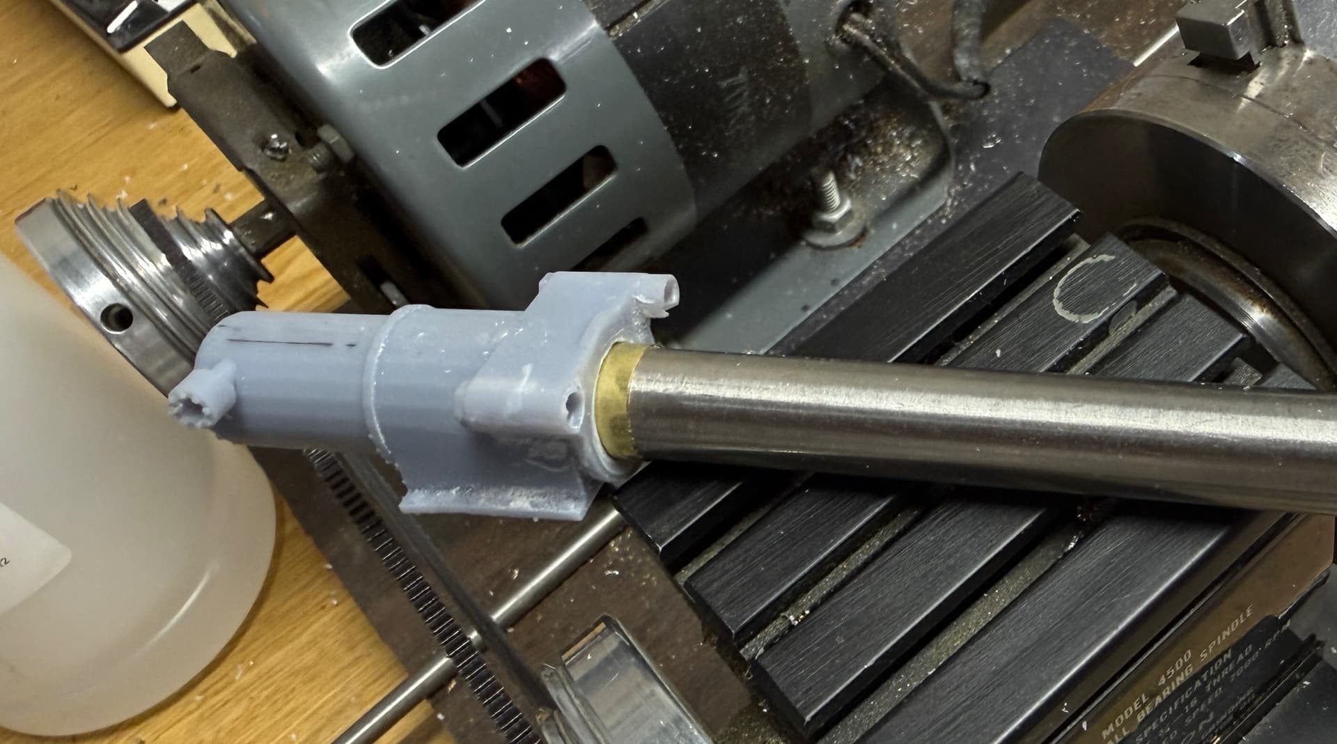
The other scheme I’m noodling is how much fo the operating portion can be 3D printed resin and how much should I machine out of metal. For example: since the ram’s themselves are polished hydraulic pistons they should be duplicated in metal. The cylinders could also be machined. The wall thicknesses of the cylinder ends is thin and resin doesn’t fair well like that. Foundations and frames can be resin, also I can fabricate brass if I have to. I’m not afraid of machining since I was a metal shop teacher in another life a half century ago.

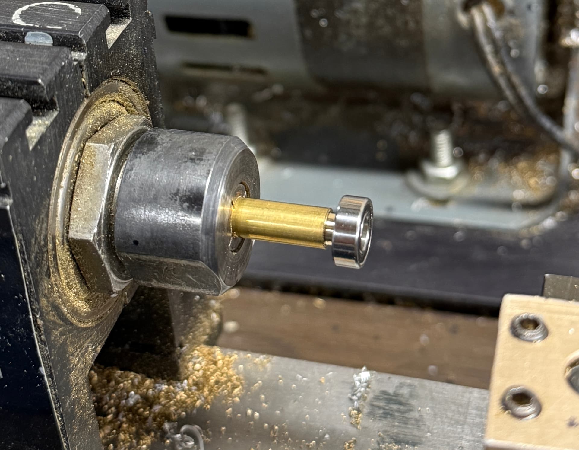
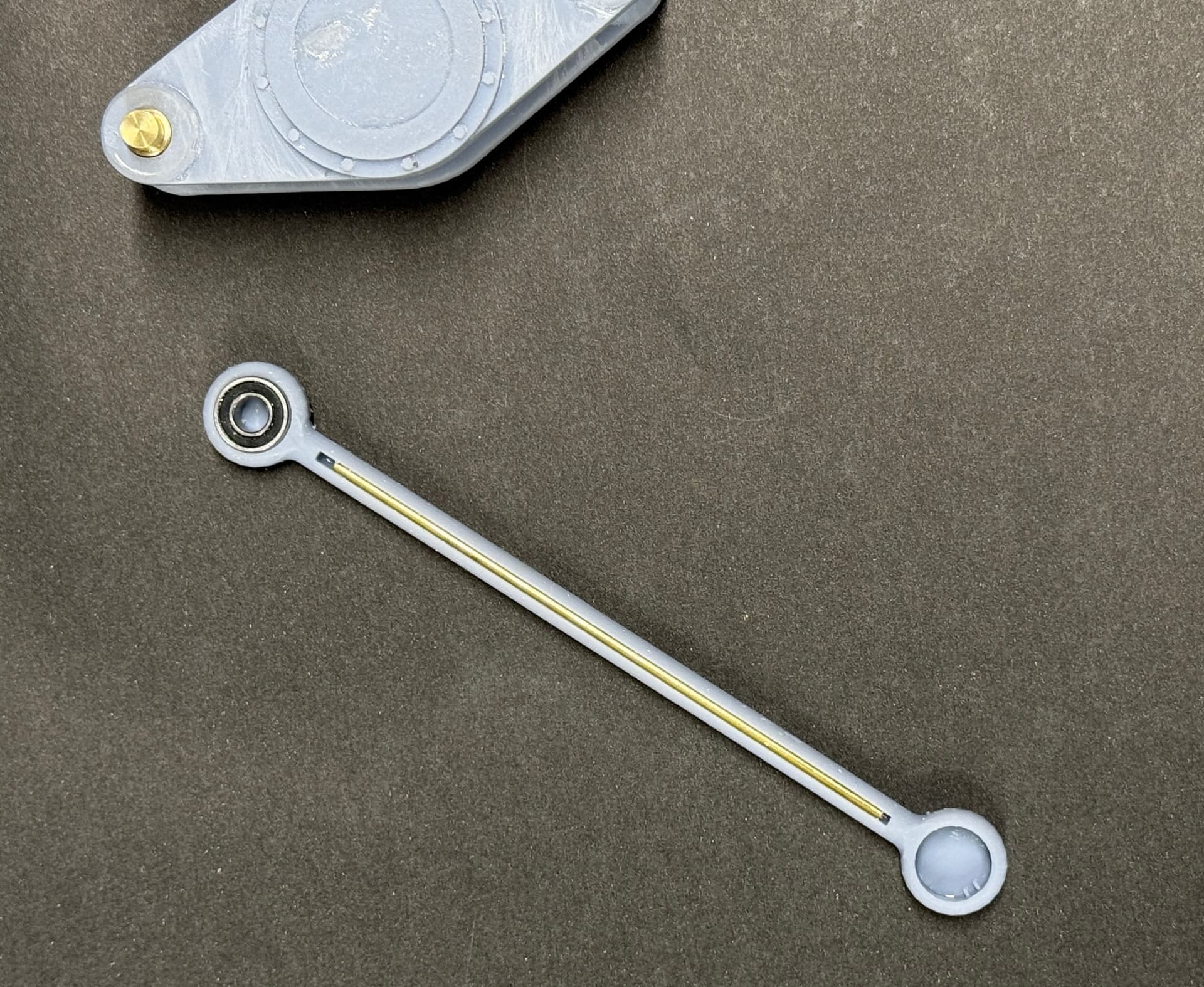
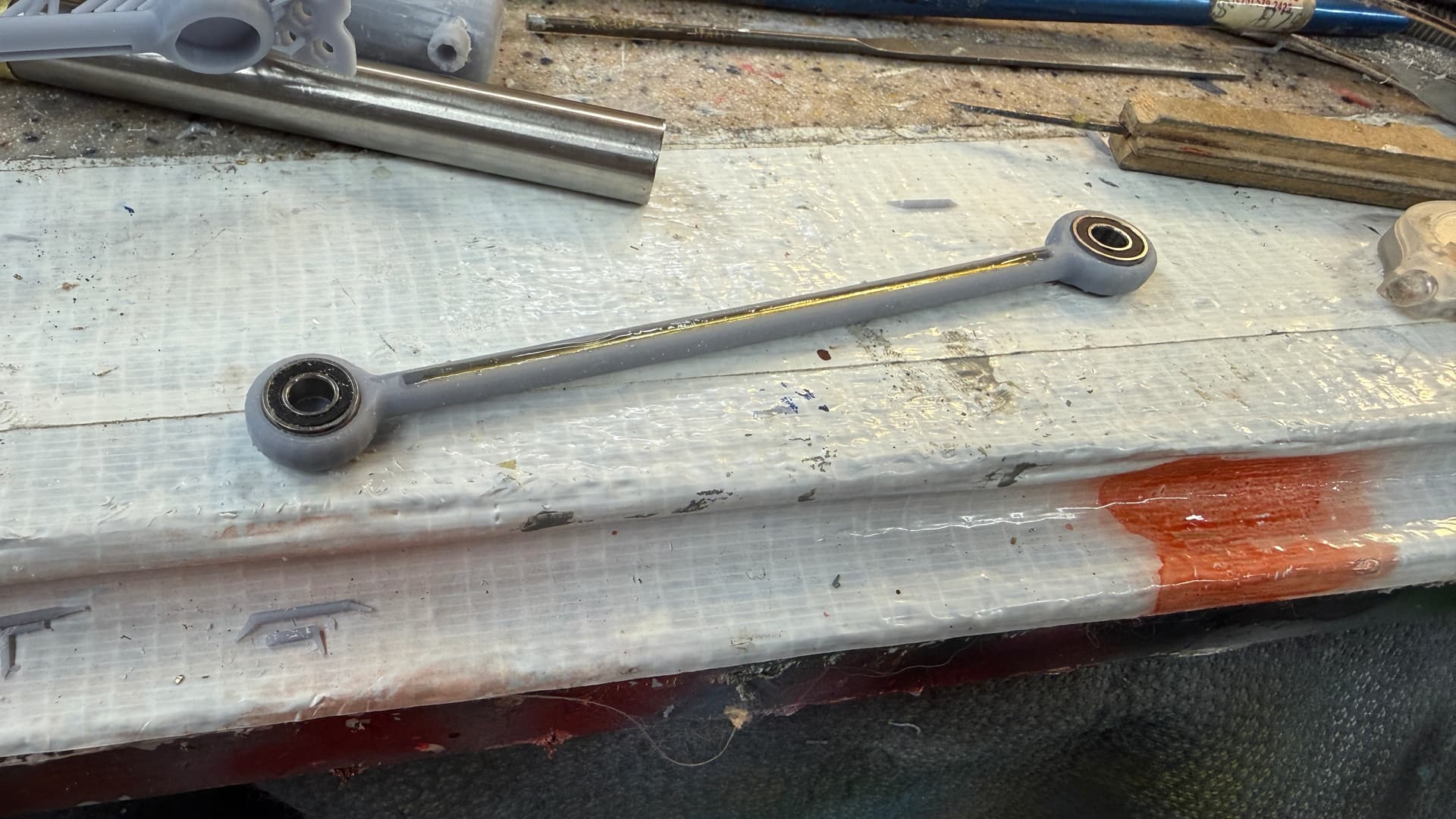
If I make the ram links out of resin, I will embed brass bearing into them and have metal spindles for all the rotating components. I’ve even been thinking about using miniature ball bearings that RC cars use to reduce any friction in the system.

Here’s how a 1:32 prop fits on the printer. At this scale the prop is almost as big as a real 1:1 outboard motor prop. It’s a shame I can’t make it out of bronze. I suppose someone could cast it for me, but that’s $$$ which I’m not spending. All those flat edges get hand shaped after printing.

So there’s a lot of thinking that will have to take place before this is done.

2 Likes

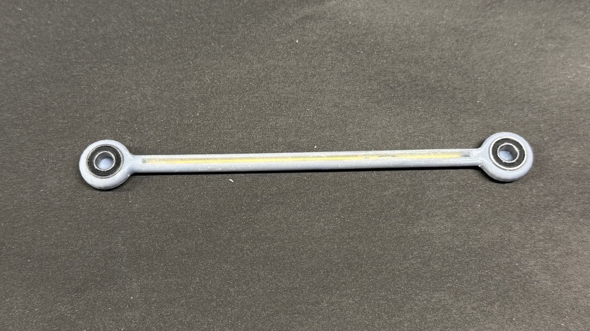
Got the first part designed. This is the 4-piece ram link that goes from the ram crosshead to the rudder crank. I’m going to use ball bearings where possible, not so much because of speed or loads, but because I want it to run for years without needing lubrication. None of the parts rotated more than 70º so spinning is not an issue. I’m not sure if the links need to physically restrained. The bearings I’m choosing are deep and all the motion is lateral, not vertical. Loads will be light since the power is coming from the rudder up, not from the rams down. If I can design the rams to be relatively friction-free, the links should not rise up. While I’m writing this, I realize that the ram links on the bottom are being pulled down by gravity and would need restraining.

Ram Rod Test.png

I’m including a 1/16" wide groove to the halfway point on the bottom of the upper and lower links to accept a 1/16" steel rod to stiffen the resin and resist warpage. I will epoxy it in with J-B Weld and contour it so it will be invisible. Whereever possible, I’m going to augment the resin with metal. The 1:1 link is retained by the four large bolts on the cover plate. They are safety wired so they do not ever get loose. Notice also the two grease fittings on the link head. There is frictiion there that needs to managed.

Ram 3.jpg

Notice the protective covers on all of the slides. This is a US Navy requirement to keep all operating machinery is a state of mechanical preservation. I will not have the slides covered. The ram is 1.5’ diameter on the 1:1 ship. On the model, at 1:32 that’s 7/`16". I happen to have some steel rod that’s 7/16. With a couple of fine finishing cuts on the lathe and polishing, I will have a great looking real metal ram. For the side crosshead guides I plan on using drill rod. I have some of that too, but I need to purchase it, it shouldn’t be expensive.

1 Like

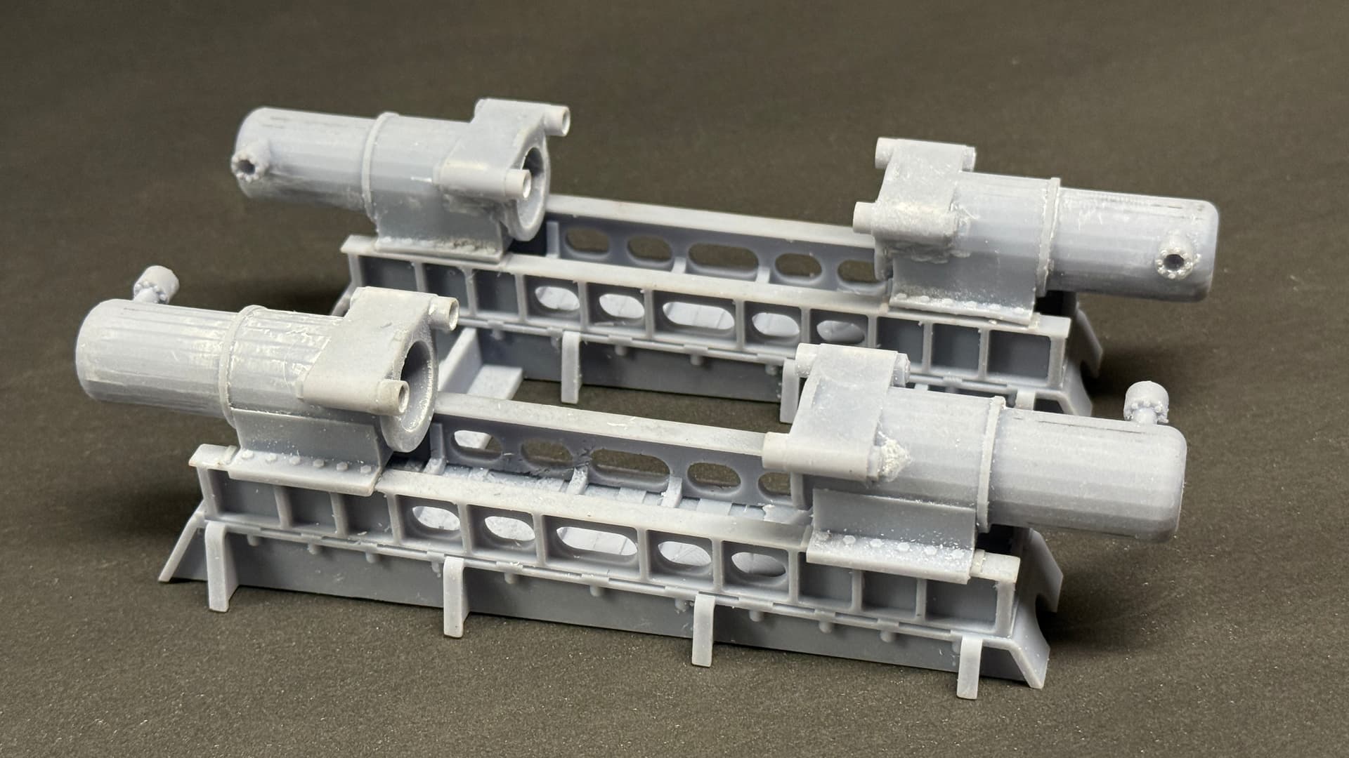
Design work is continuing even on Father’s Day (or becasue it is). Of course it’s never easy. The bias that the starboard side machinery sits compicates working in SketchUp and the slanted floor adds to the fun. The anti-corrosion protection covers are blocking some of the more esoteric details like how the ram crosshead is tied to the slides that flank the sides. It’s also difficult to see in pictures and in the drawings how the crosshead looks below the ram. The drawings I have are not about buidling the machine, but how the machine is situated within the space. I am making a big assumption that the draftsman that drew the machine was using accurate measurements to do it. i got the two-layer foundation bed most drawn.
This shows that angular bias that the starboard side machine has. The port side machine, on the other hand, is in line with the ship’s centerline. Don’t know why this is, but everything is the ship’s architecture is done deliberately, so I’m going to assume they knew what they were doing.

This is the work done so far. I don’t have an end view of the machinel; only top and side. For end views, I’m relying on pictures were took.

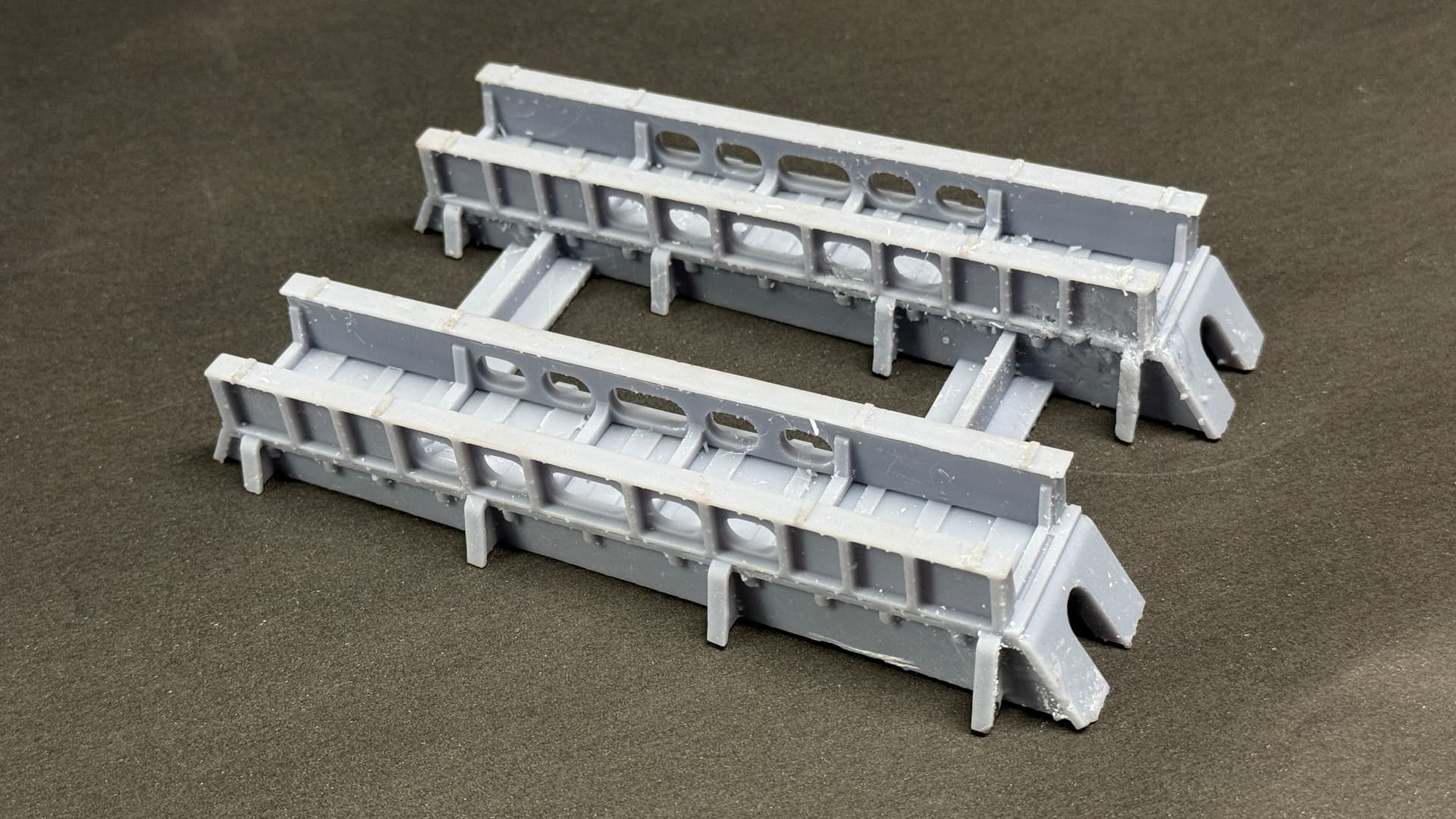
I will be printing the base in two parts to ensure that all of the geometry is faithfully captured.

I thickened the webbing on the lower base to give it more heft in the printed part. If I wasn’t going to animate this, the construction would be very simple. Once I decided that parts needed to move and, more importantly move for years and years without attention, design became more engineering and less art.

My youngest grandson, who just graduated as a mechanical engineer, is home for a month until he starts his real job in August. He’s going to “consult” with me on the design and he’s also an expert at programming Arduino micro-controllers. We’ll breadboard the operating mecahnisms to fine tune their design. He and his mechanical engineering brother both blame working with me in my shop for reasons why they chose this profession. Both were hired at good companies before graduating.

1 Like

Design work continues. I’m working on several fronts simultaneously; the ram, rudder and operating mechanism. I have many decisions to make. While engineering the rudder stock bearing system under the base was easy, I don’t have a clue. The 3D printed rudder forging, rudder bearing support and rudder stock are complicated parts and there’s no apparent place to squeeze in a ball bearings. I may have to rely on sleeving with brass to prevent resin-to-resin surfaces.

The rudder forgings are hollow structures with is helpful in making resin parts. Save resin without sacrificing strength. You just have to have drainage holes to be able to evacuate the liquid, un-cured resin that resides within.

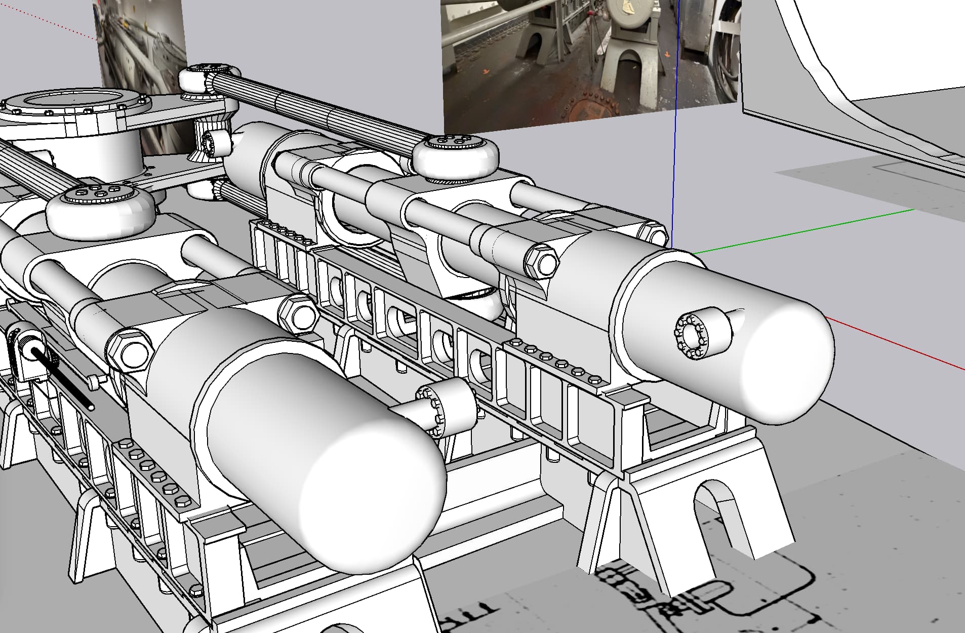
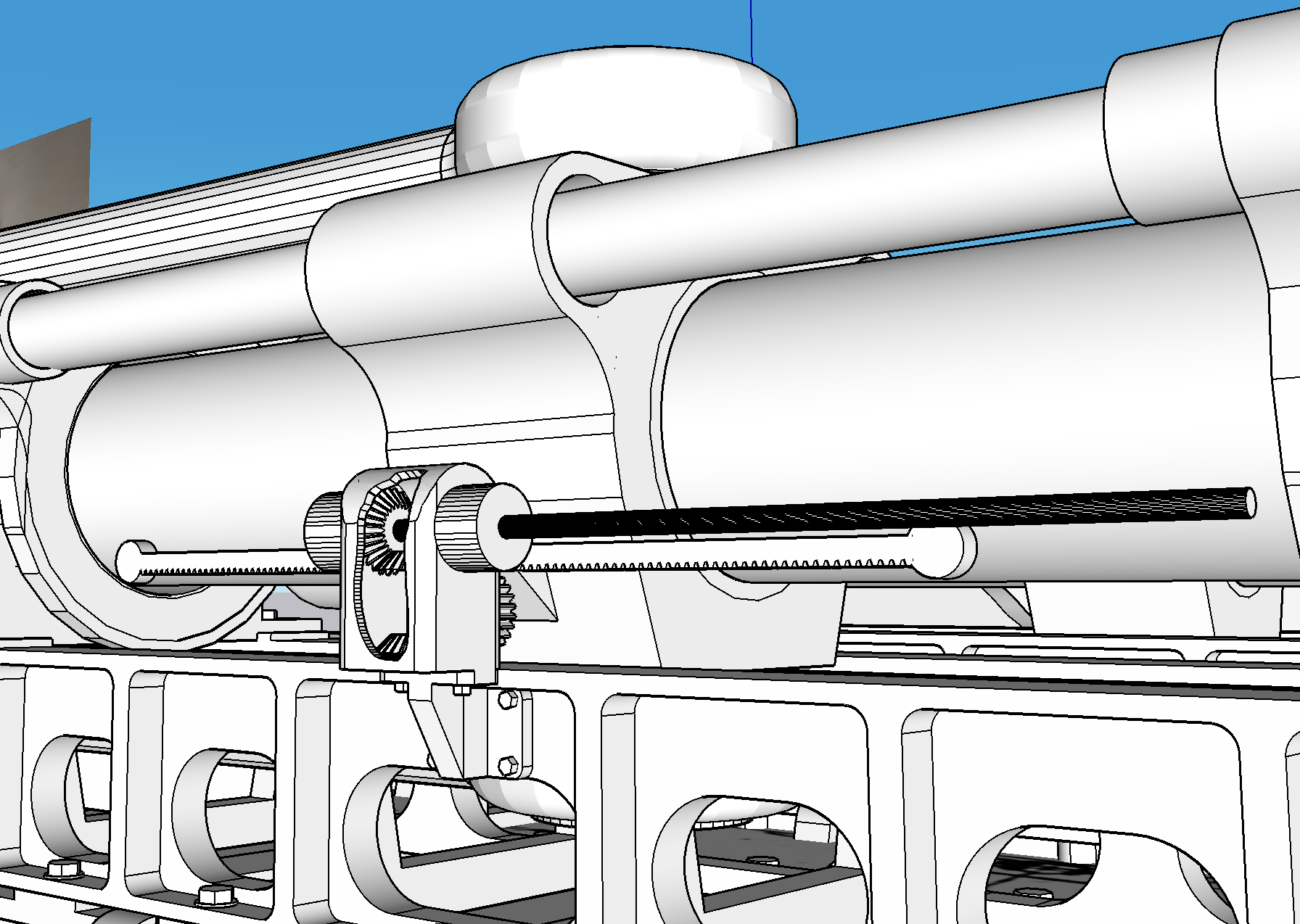
​The ram assembly now has crosshead and crosshead guides. The ram and crosshead guides are polished stainless steel rods. I’ve sized them with nominal dimensions that will allow me to use standard brass tubing with a sliding fit i.d. for crosshead bearings. There’s more detailing on the cylinders. I have to add hydraulic pipe flanges to their ends. And there’s a rudder position indicating device in the hydraulic compartment that’s driven by a rack and pinion arrangement. The rack moves with the cross head and the pinion motion is transmitted to the meter via a stout steel shaft with unviversal joints. I will model, but not animate this.

I don’t have good information about the bottom supports of the rudder top. I have a ragged 3D scan I took of it during my visitaton. Some fragments of views from the still pictures show a bit here and there, but not enough. I’ve asked Ryan to take some more specific pictures of that area. It’s probably where I can hide the upper bearing.

Here’s a progress shot of the rudder hub. I have drawings for four sections with three shown here. Those wings on the upper one are welding flanges to weld this structure into the ship’s framing. I’m going to try to include this feature to help tie the same part into the model. The rudder stock (shaft) scales to 8" and fits my printer (just barely) in 1:32. The lower extension is my added shafting to go below and be driven by the servo. The rudder is just wide enough at the bottom to hide it. If not, I will go to a smaller diameter shaft.
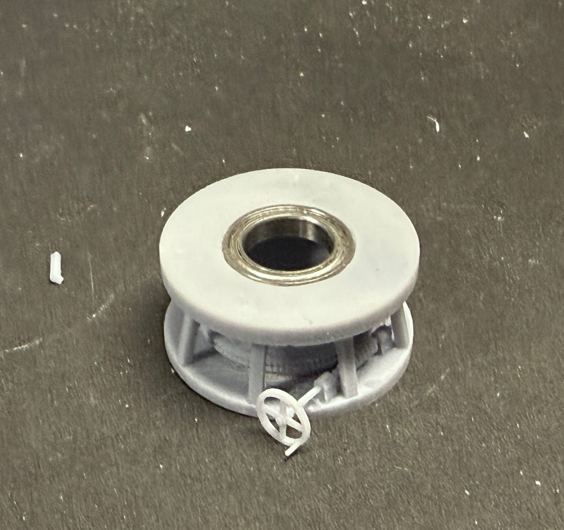
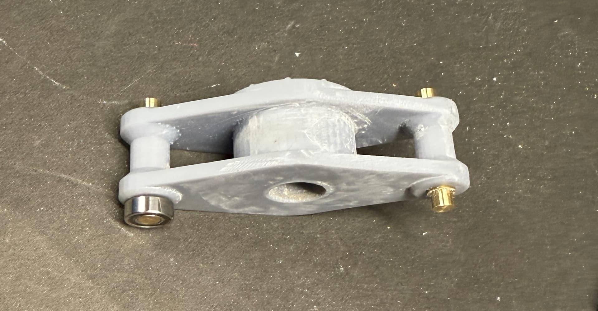
Underneath I’ve started specifying the operating components. I chosed the servo, the bearing pilow blocks that wil faciliate assembly, the micro-controller and power supply. The latter is already in the shop. Rudder travel is 35º in each direction.
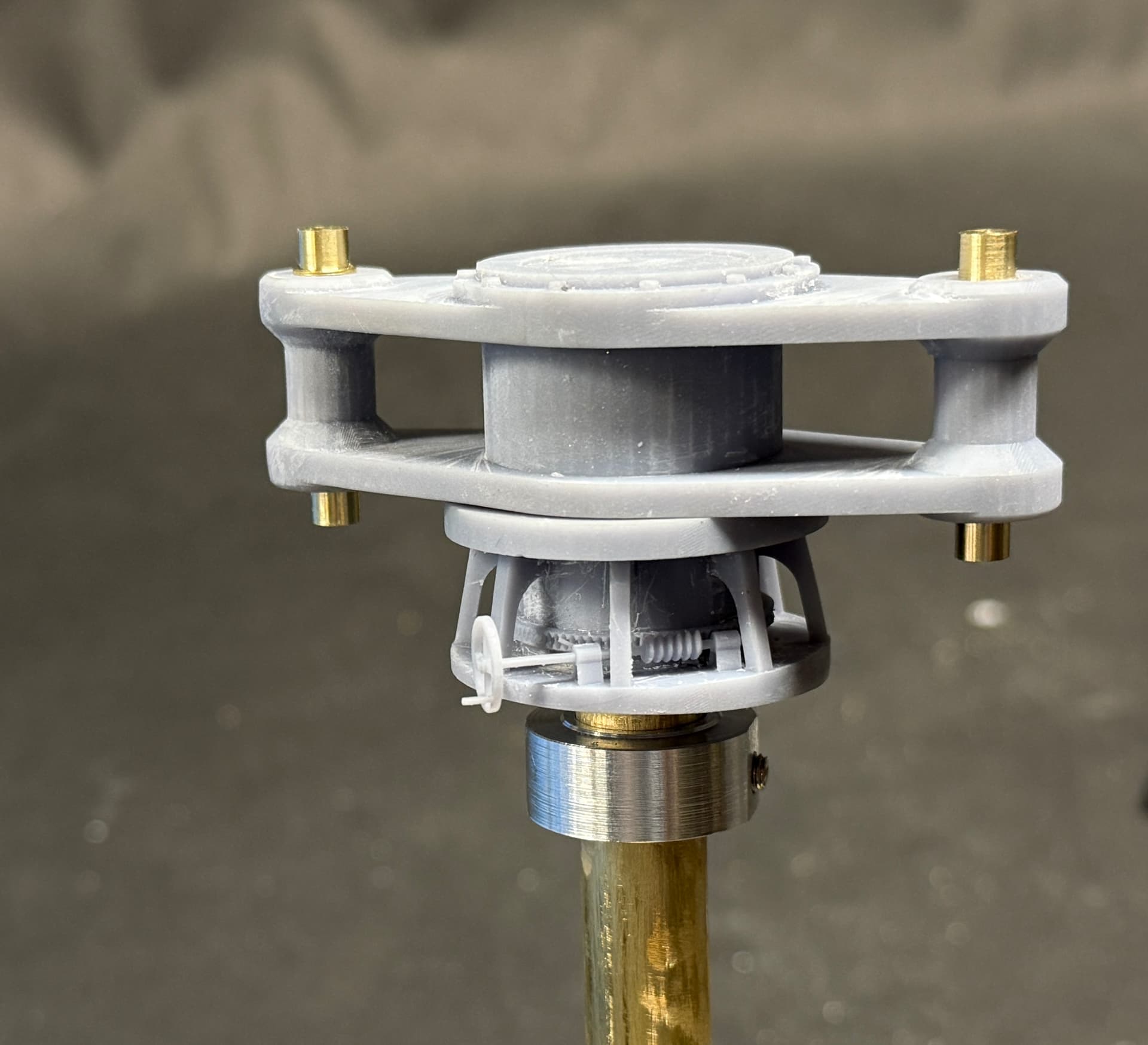
There is a bottom pillow block that’s connected to a bottom plate. Having two bearings at the bottom should provide a stable shaft regardless of what I decide for the upper works.

1 Like

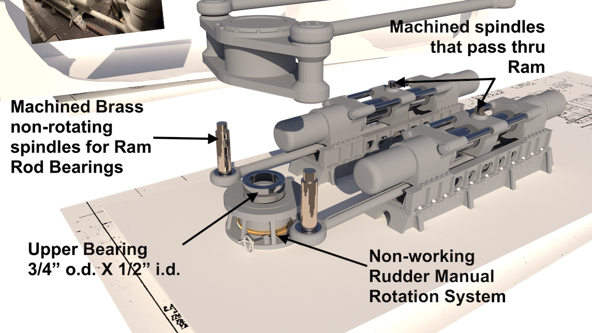
The upper bearing is now engineered. It’s fitting into socket at the top of the rudder stock. The rudder stock itself will be non-moving. The motion will be carried with a 12.7 mm (1/2") rod fitted to the bore of the upper and lower ball bearings. This means that the rudder will be connected to the inner rod, not the stock. Complicates things a bit, but there was no way I cuold get the stock to work with the space for the bearings. The real thing uses sleeve bearings in the rudder hub.

I was able to figure out what the rudder hub base looked like from a few glimpses in the images I had plus a very ragged 3D scan I make with Scaniverse on my iPhone 16 Pro. There is a hand wheel driving a worm gear to a large pinion on the rudder stock. Supposedly, you can turn the rudder manually through this mechanism. I am dubious…

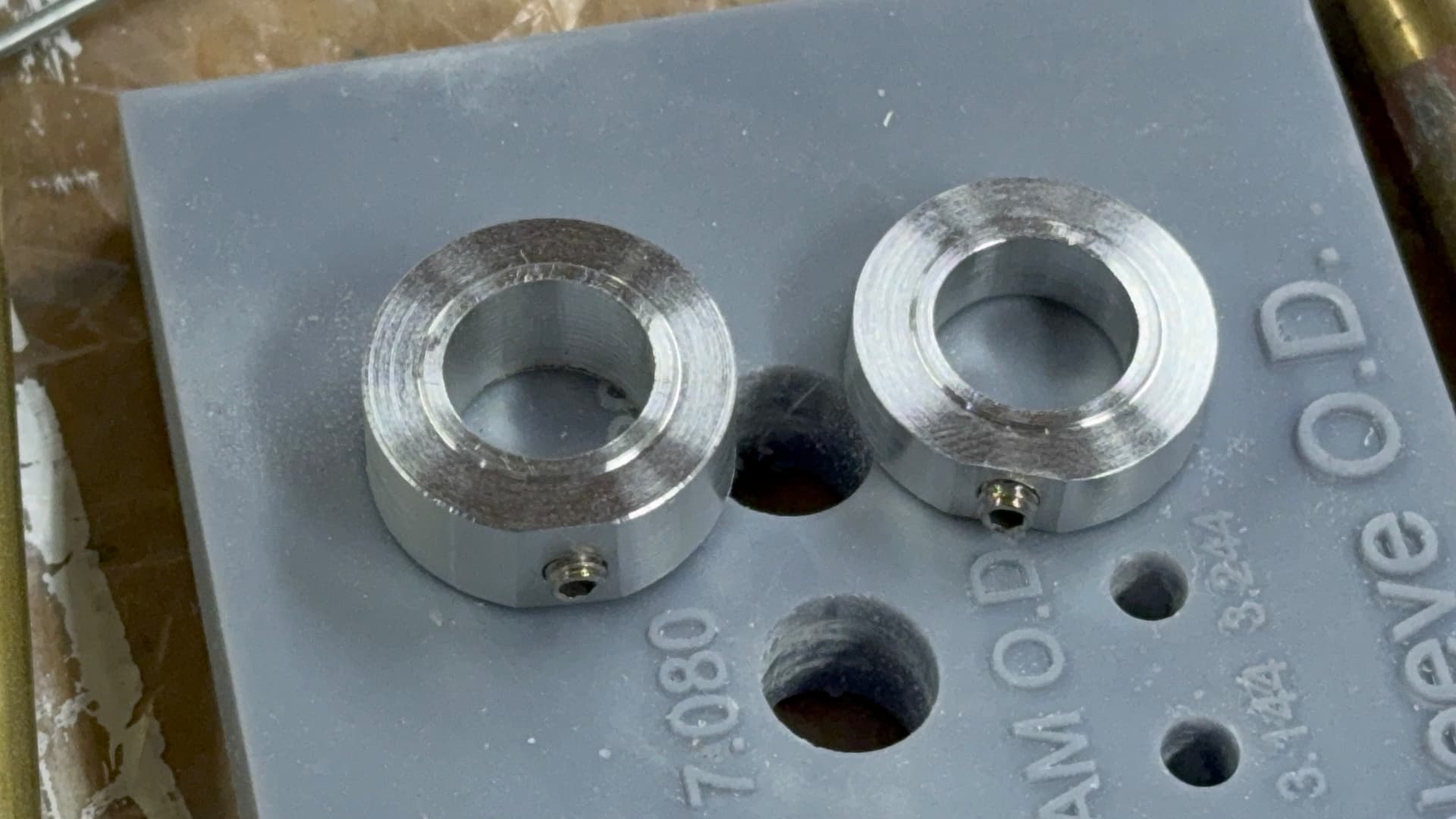
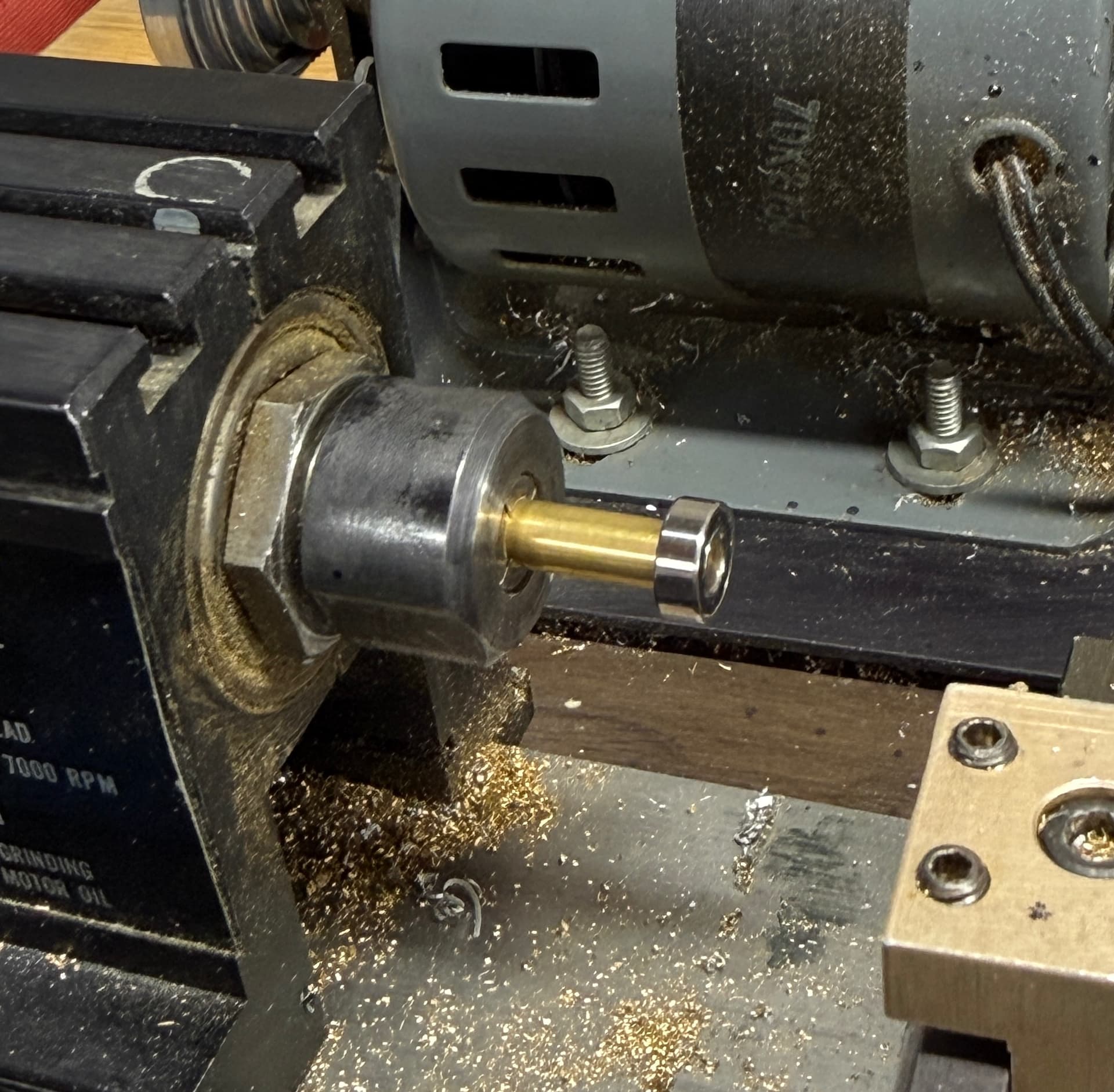
I found some ball bearings that will fit inside the rudder stock. They’re 3/4" o.d. X 1/2" i.d. and 5/32" thick. Perfect! The outer race will be captivated by using a small amount of epoxy. Also shown are the two machined brass spindles that hold the inner races of the ram rod bearings. Again, the outer races will be somehow captivated in the ram rod heads and the inner race will be a light press fit onto the spindles. There are two more brass spindles to support the ram ends of the rods. These will pass entirely thru the rams serving the mount for the ram rod bearing and locking the cross head to the ram. I will be machining these. They don’t rotate, only the bearings and the ram rods do.

I’ve started buying materials for the mechanics. I need to have them in hand to ensure that the printed parts conform to the sizes I’ve chosen. This model is costing more out-of-pocket than the previous ones due to the animation, but it will be worth it if I can pull it off.

I’m procrastinating designing the rudder hub and upper forging due to their complexity in drawing and printing challenges.

1 Like

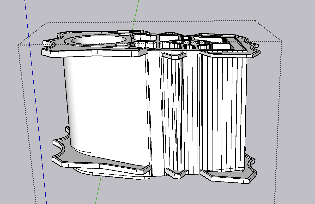
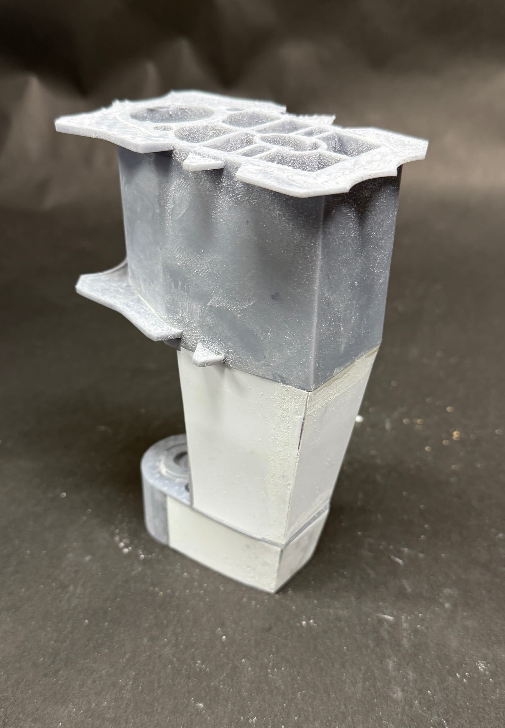
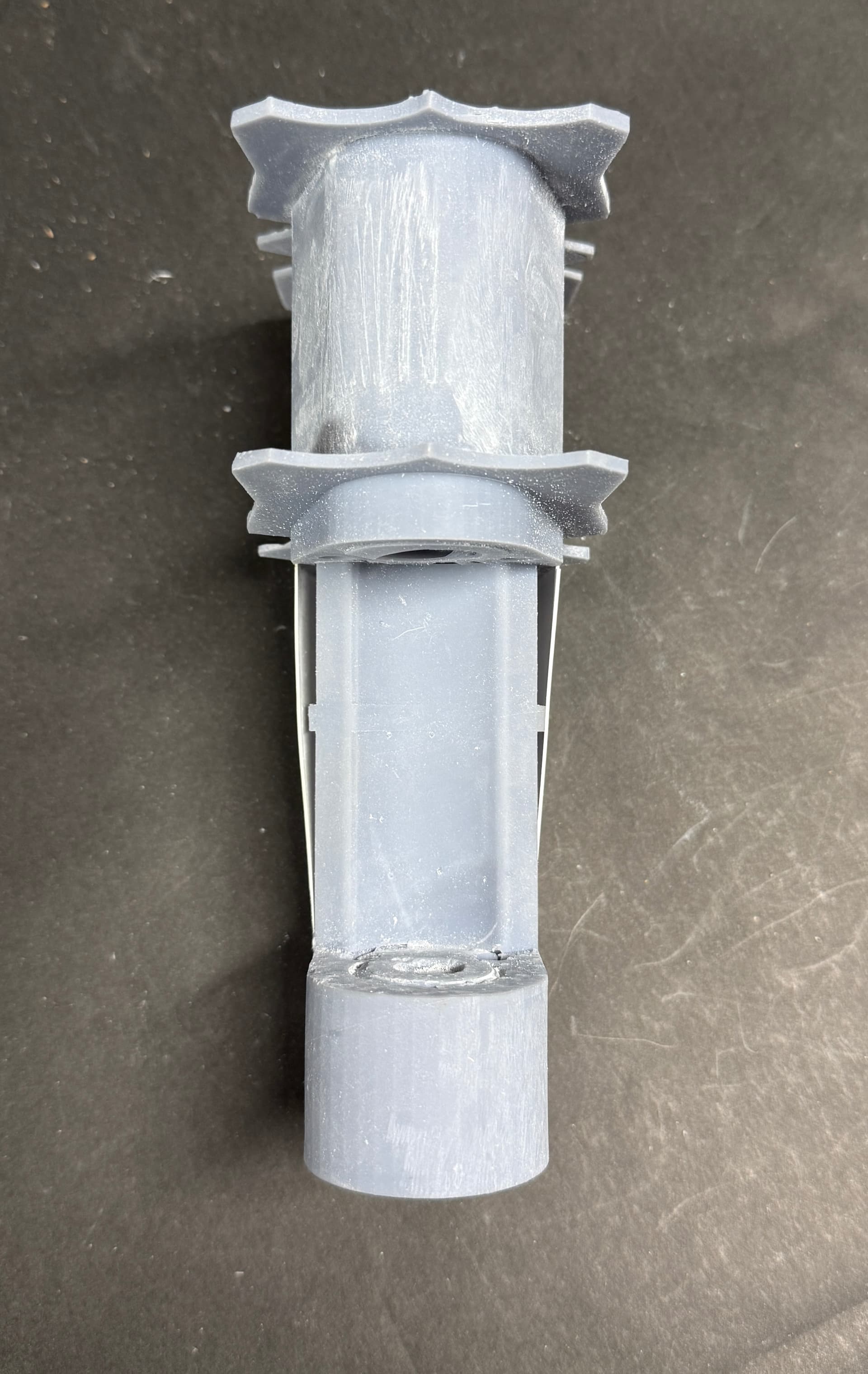
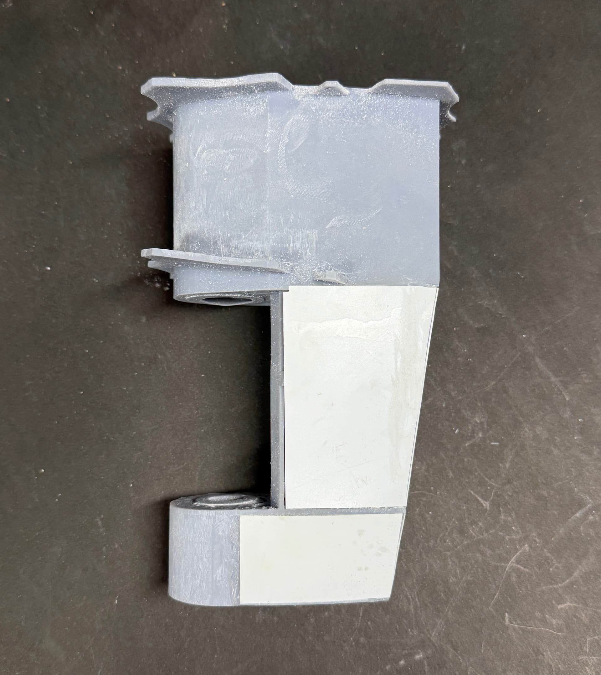
My procrastination was correct. The rudder hub has taken hours of design work and I still don’t have it done. Two things, so far, are complicating things. The weld flanges are not square with the part. Instead they are slanted according to the lay of the ship mold lines. I had to chop the top off the upper section to a slight angle corresponding to the floor angle of the machine room. The lower plate is slanted even more with the line of the hull at the bottom. I drew them square, removed them and then rotated them to the correct angle. The second problem was worse. How to skin the sides of this complex part? My first attempt took a few hours, but it was a bust. It wouldn’t/couldn’t print. The skin had no depth. That breaks rule number 2 of the three rules about designing for 3D printing. To add depth to the walls was an exercise in futility. I’m going back to old school. I’m going to skin the contours with 0.040" styrene sheet glued into gluing lands I’m designing in the part.

Here’s the upper part showing the angularity of the upper surface and weld flanges. The walls on this part are thick and will print. Note: This part has no taper making it easy to just extrude the walls to the desired height.

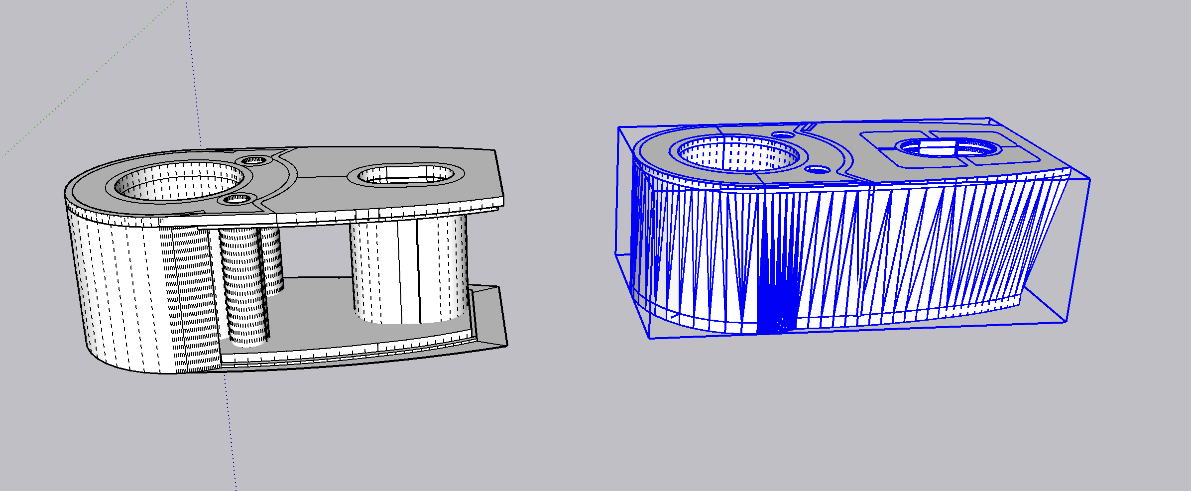
Here’s the comparison of the first attempt and the second. When the first attempt is exported as a printable STL file, the side walls, without thickness, disappear. Something that has no depth can’t exist in our 3 dimensional world. Everything that can exist has thickness unless we’re talking about an electromagnetic wave. All those zig-zag faces has to be hand woven and it took a lot of patience and care.

This part is not yet complete. It has a center section with more taper and it has a fairwater leading edge that has to be drawn and printed OR made model RC Plane style by carving a block of balsa or carving foam. I can even make the shape out of clay and cast a resin shape to do it. I can also skin the shape with balsa. I have experience with balsa and styrene. I do whatever is least expensive. This part supports the rudder, but the rudder itself will be skinned with balsa and be very light weight.

On another tack…

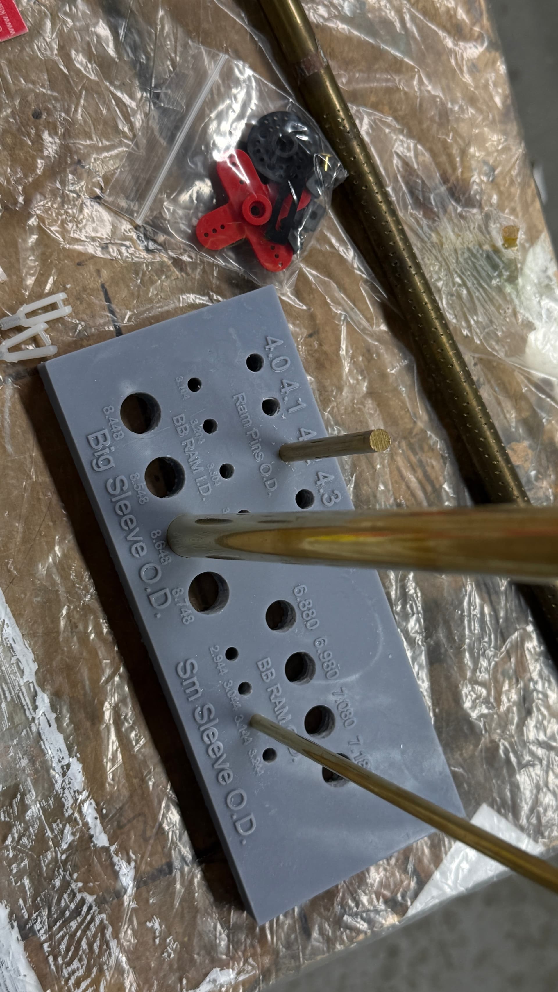
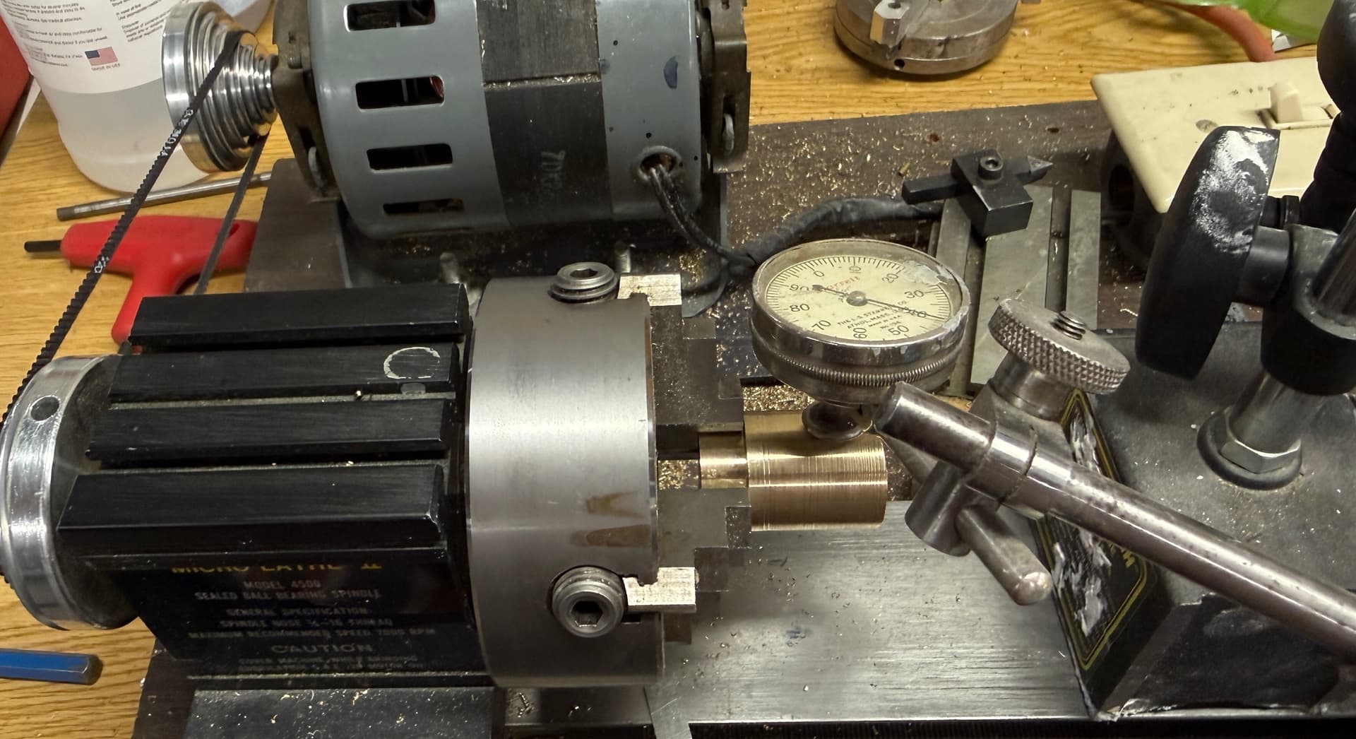
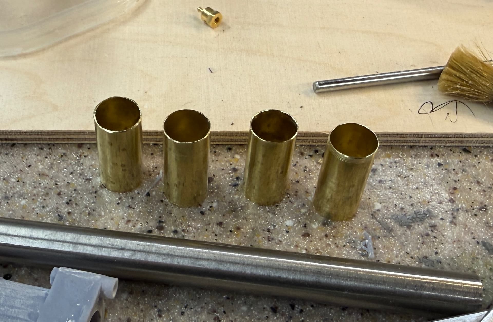
I got all the materials for the machinery either in hand or ordered. The stainless steel rod stock arrived from Amazon and I picked up the KS Metals brass tubing that will serve as the sleeve bearings. The fit is, by design, perfect.

All I have to do is cut the shafts to length. There will be no polishing or finishing needed, and being stainless, I won’t have to worry about corrosion occuring over the years the model will be on display.

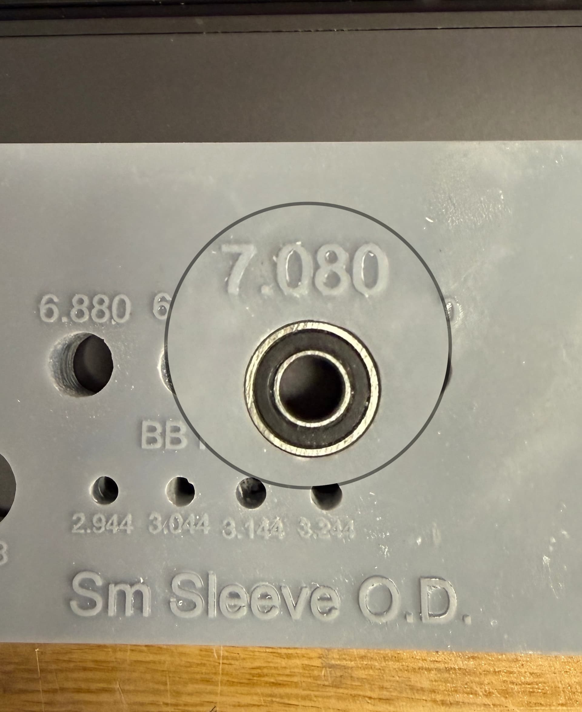
I’ve got the bearings in hand and will design and run a test article to find the right diameters for the various sleeve and bearing mounting holes. Just telling the printer I want a hole of X size doesn’t guarantee that it will be that. Most likely it will not. The resin expands and changes during printing and post curing. For most applications this usually does’t matter. But here I’m trying to print holes that are going to be tight fits on bearings and machined pins. For the pins that I’m machining, I adjust the size based on the actual hole, but in the case of finished bearing and sleeves, I have to print the holes the right size. For through holes, I can open them up if they’re too small. Not so for blind holes like the cups that will hold the tiny bearings at the ends of the ram rods. These will have to be right.

So I’m creating a test article with a series of holes representing those needed in the model. I have converted all the key dimensions to full-size 1:1 to draw them in SketchUp and will reduce to the 1:32 scale. I will start with the actual recorded size of the bearing/sleeve o.d.s and then enlarge by small increments. I will note their sizes on the print itself. After printing, the sizes that work best will be incorporated into the model’s design. It will be much easier (and cheaper) to print on piece with a bunch of holes than to print the real complex parts of the model only to find that the bearings don’t fit.

Can’t you just use a drill to “size” the hole to the correct ID? Print it a little tight, and the drill should clean it up and give you a perfect fit throughout the length of the bearing. Just my 2 cents, which is probably what it is worth.
Marvelous work. I love watching you create these masterpieces.
Bob

I answer your question later in this report. Under normal circumstances, a drill would be the correct choice. But these are not ‘normal’ circumstances.

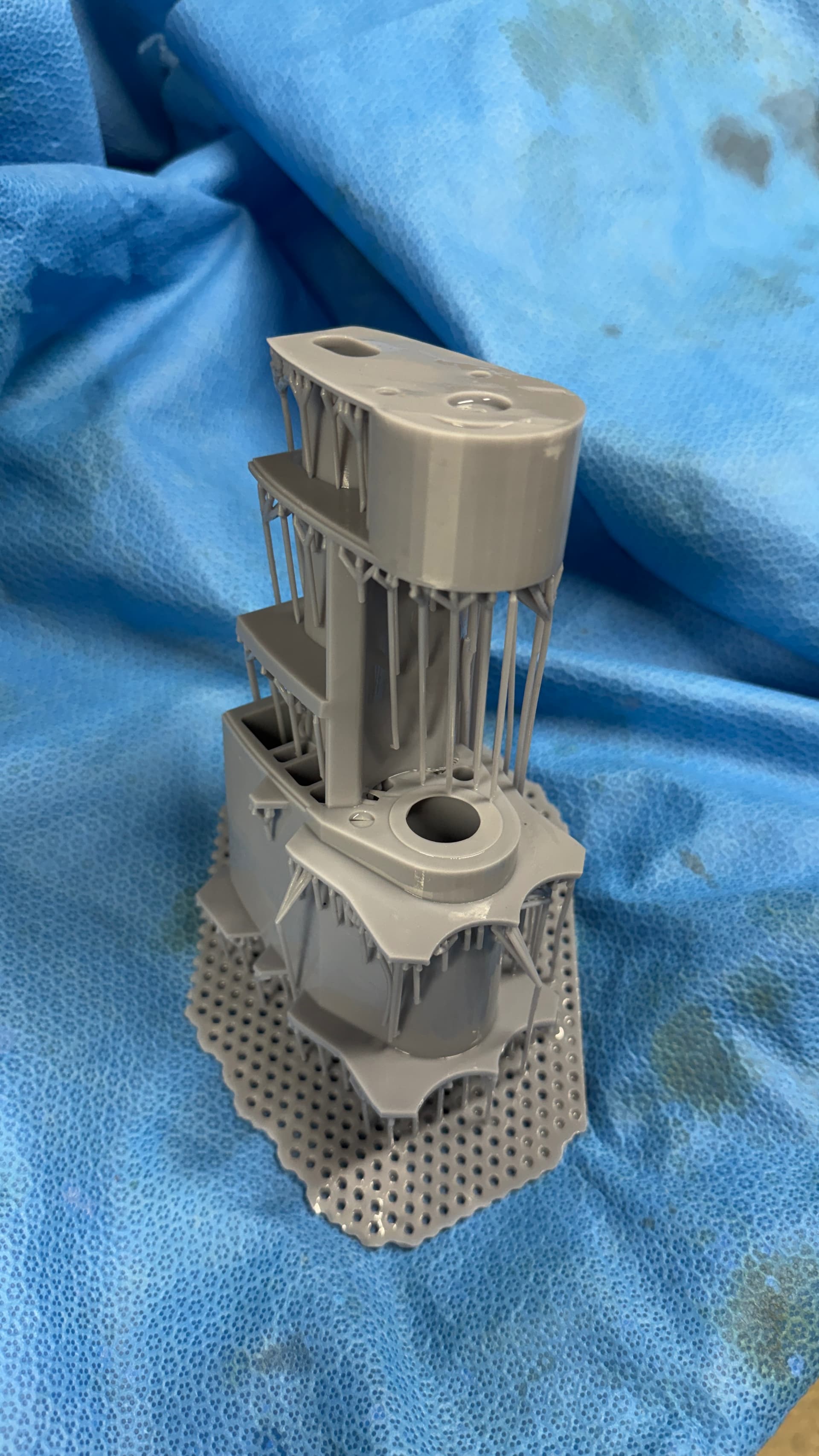
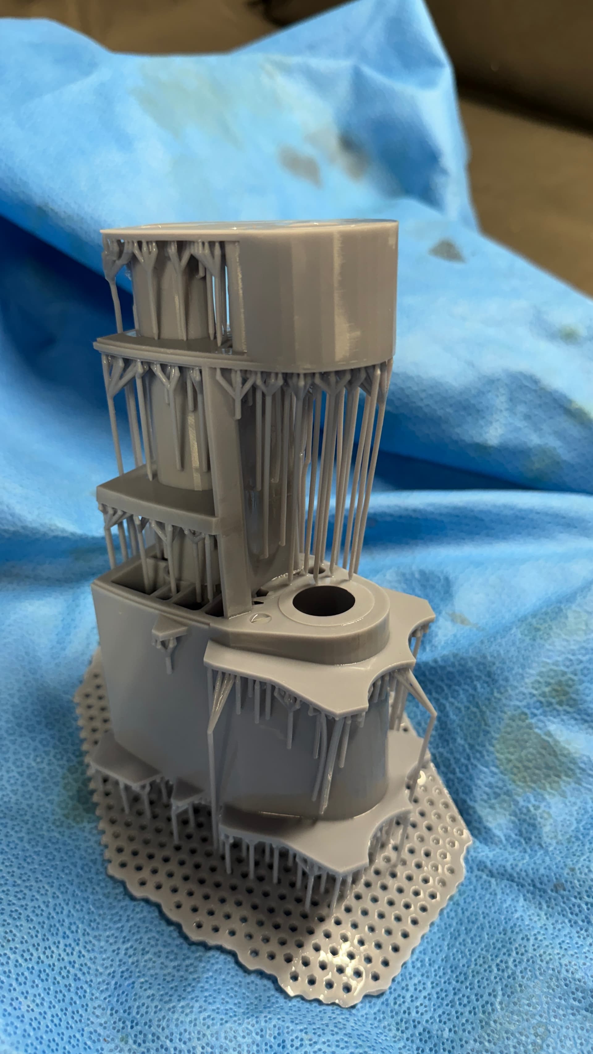
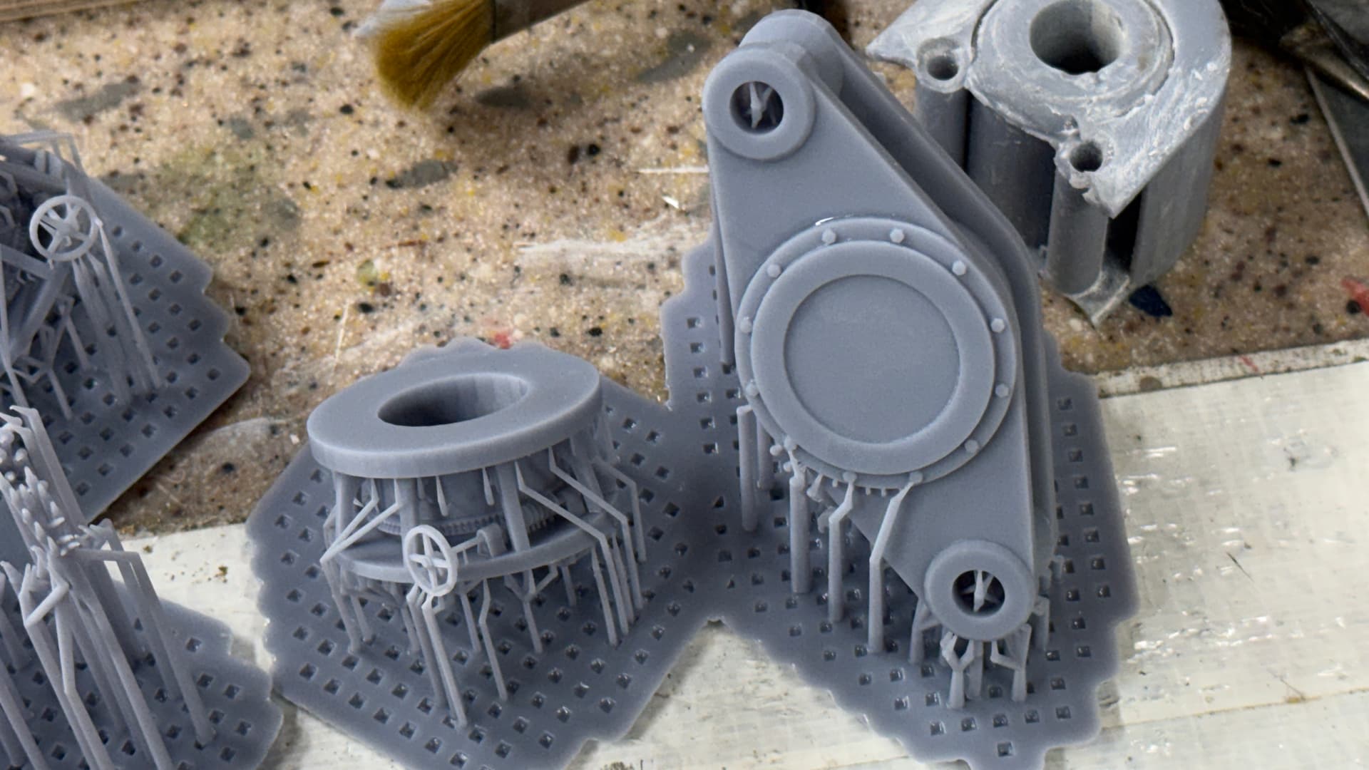
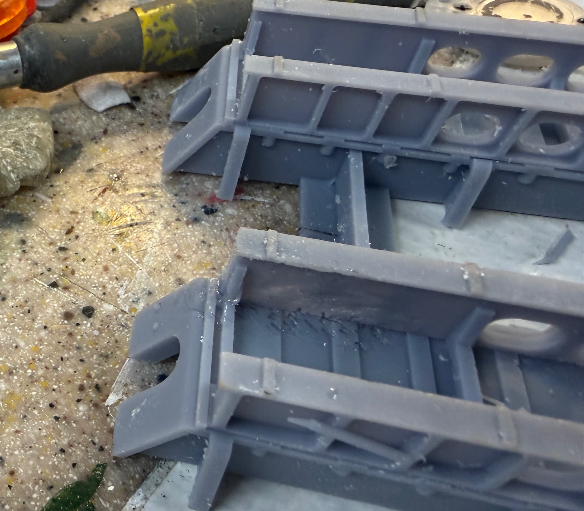
As per my usual MO, I’m starting to print the rudder project with—what I considered—the most complicated part to design and print in the project; the rudder hub. After getting a successful print—Success as defined by the part forming properly—but was unsuccessful because the STL file I created from the drawing lacked part of it AND after examining the finished print I found things I needed to modify. This is a BIG part!

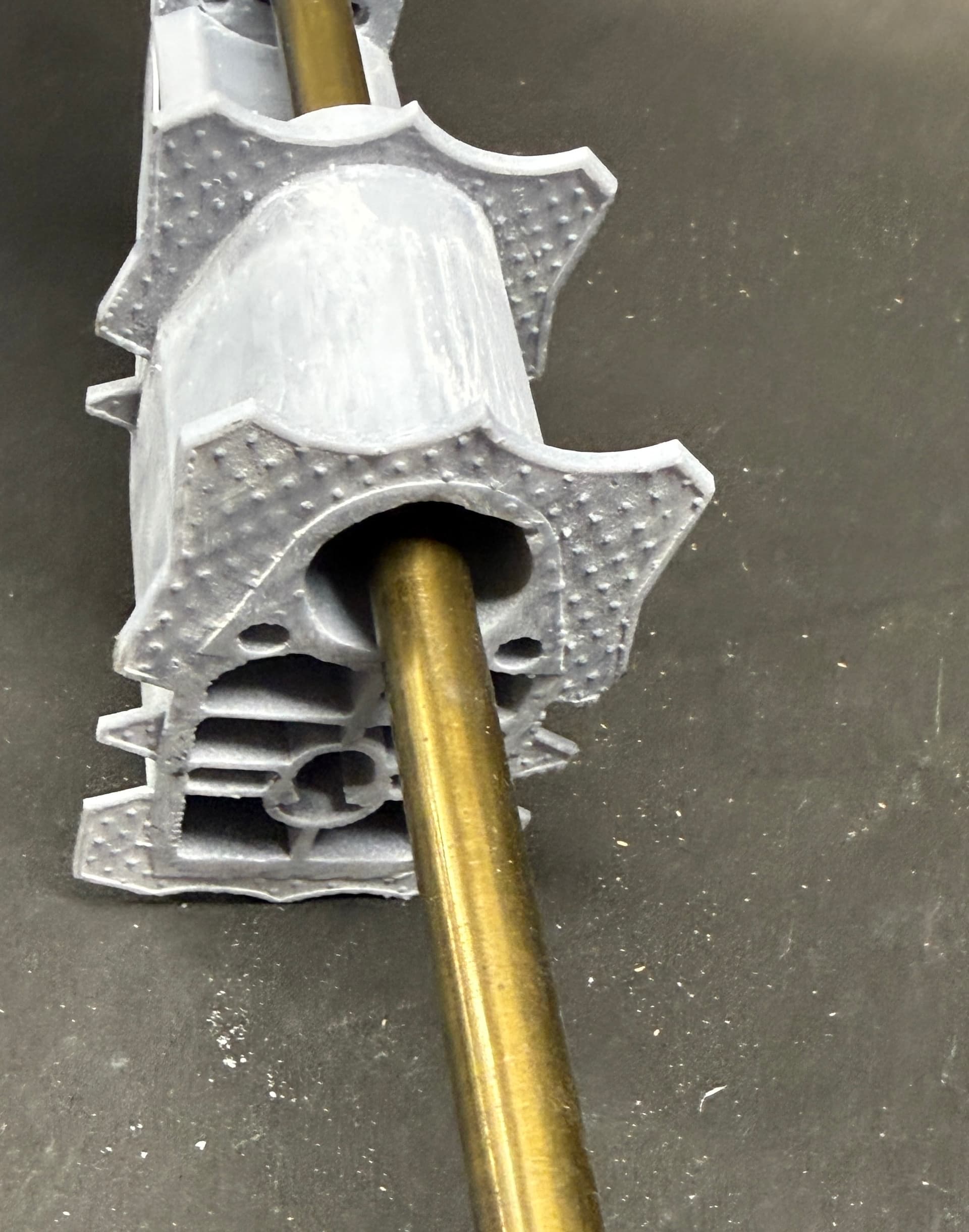
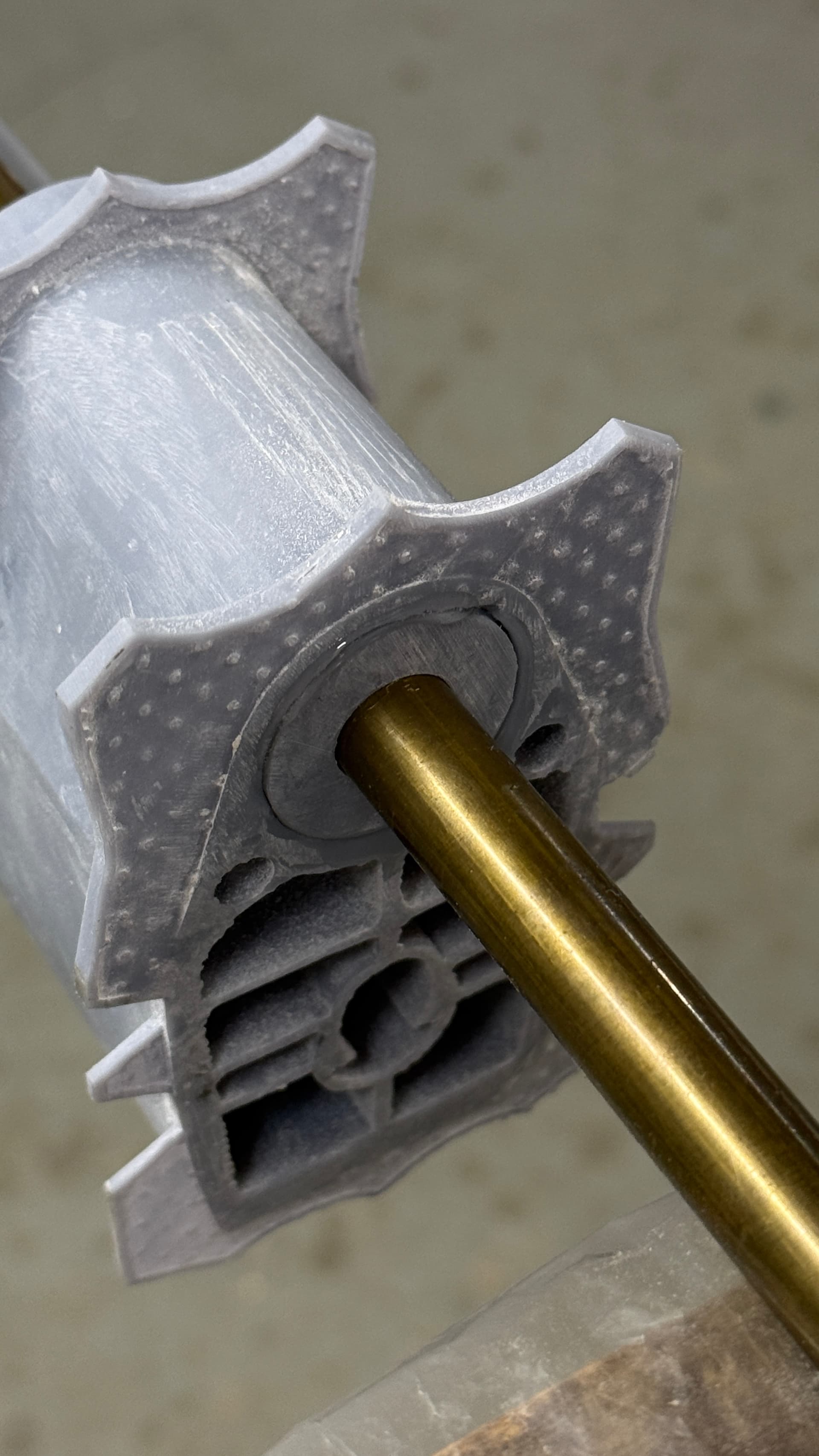
See that big hole in the bottom portion. That hole should be 1/2" diamter to accept the “real” rudder stock—a piece of 1/2"dia brass rod. The sleeve I drew to properly size the hole wasn’t grouped with the rest of the part. When I selected the part to be converted to an STL, it left the sleeve behind. The design problem was the little raised flange on the edges of the open areas. Those flanges are supposed to be the surface to which the balsa or styrene sheeting is supposed to join. The sleeves are just too small. The upper portion will remain open as this is encased within the hull. The lower portions are in the water and needed to be faired in. There is also a leading edge, called a fairwater, has to be applied that serves a similar purpose as the leading edge on an airplane wing… reduce drag and direct flow. I’m either going to print bulkheads and skin this portion like the rest or make it more or less solid. Bulkheads is prototypically correct and uses much less resin.

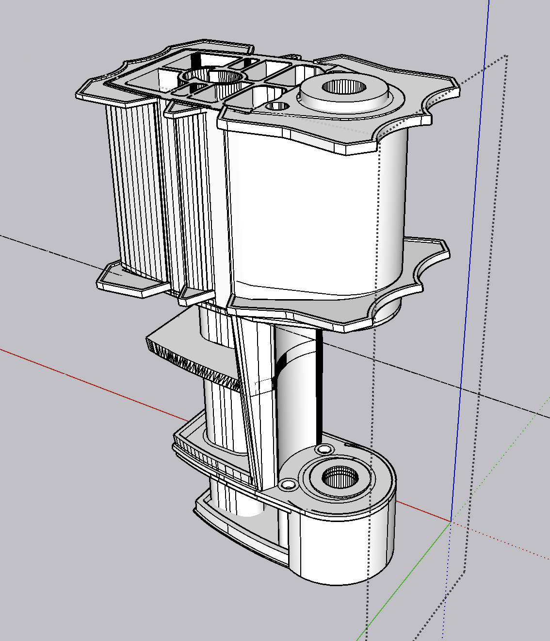
This is the redesigned rudder hub showing the enlarged flanges and properly sized rudder stock hole. I’m going to use the weld flanges on the part just as they are on the real ship; to provide more surface area for support.

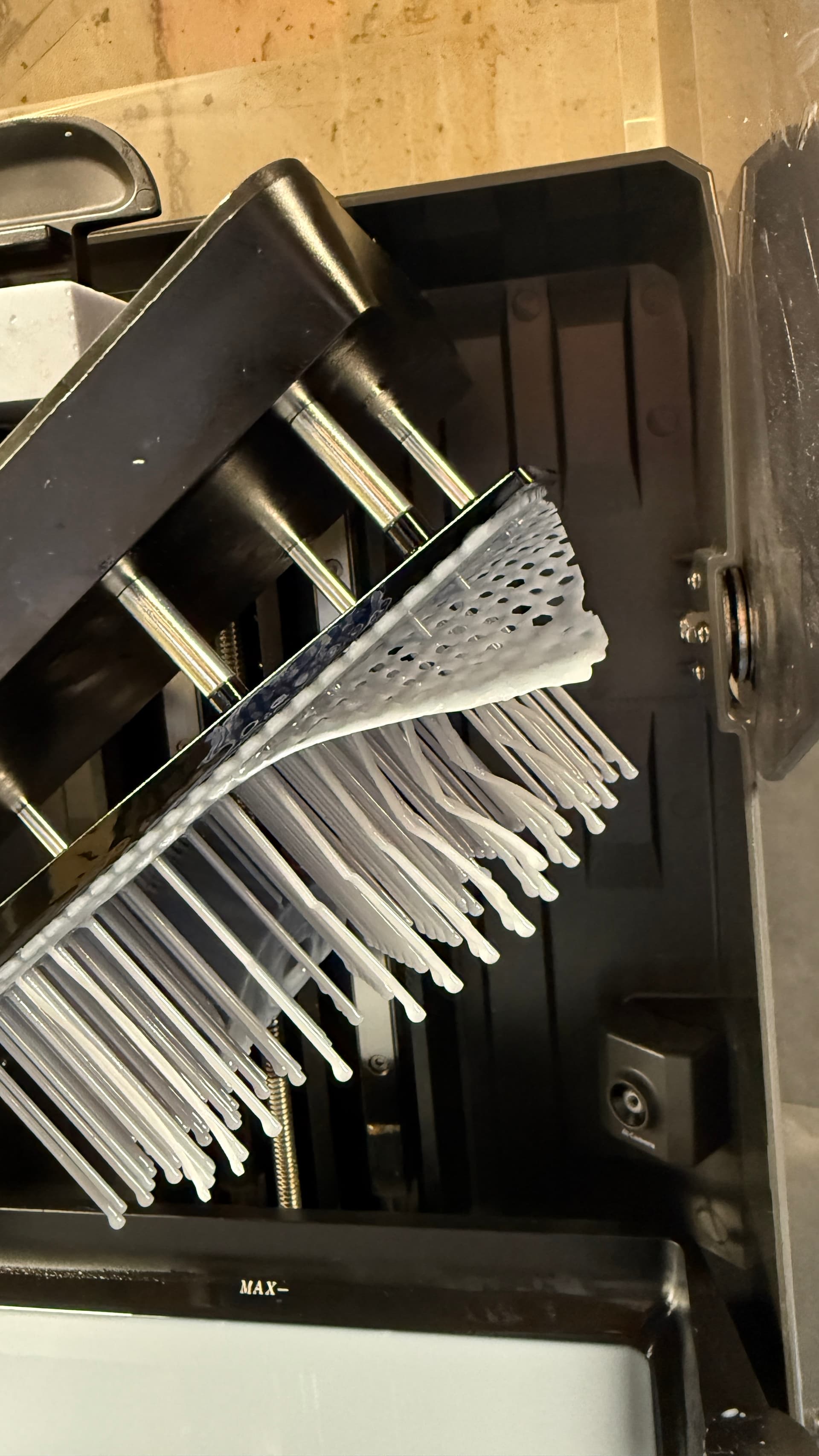
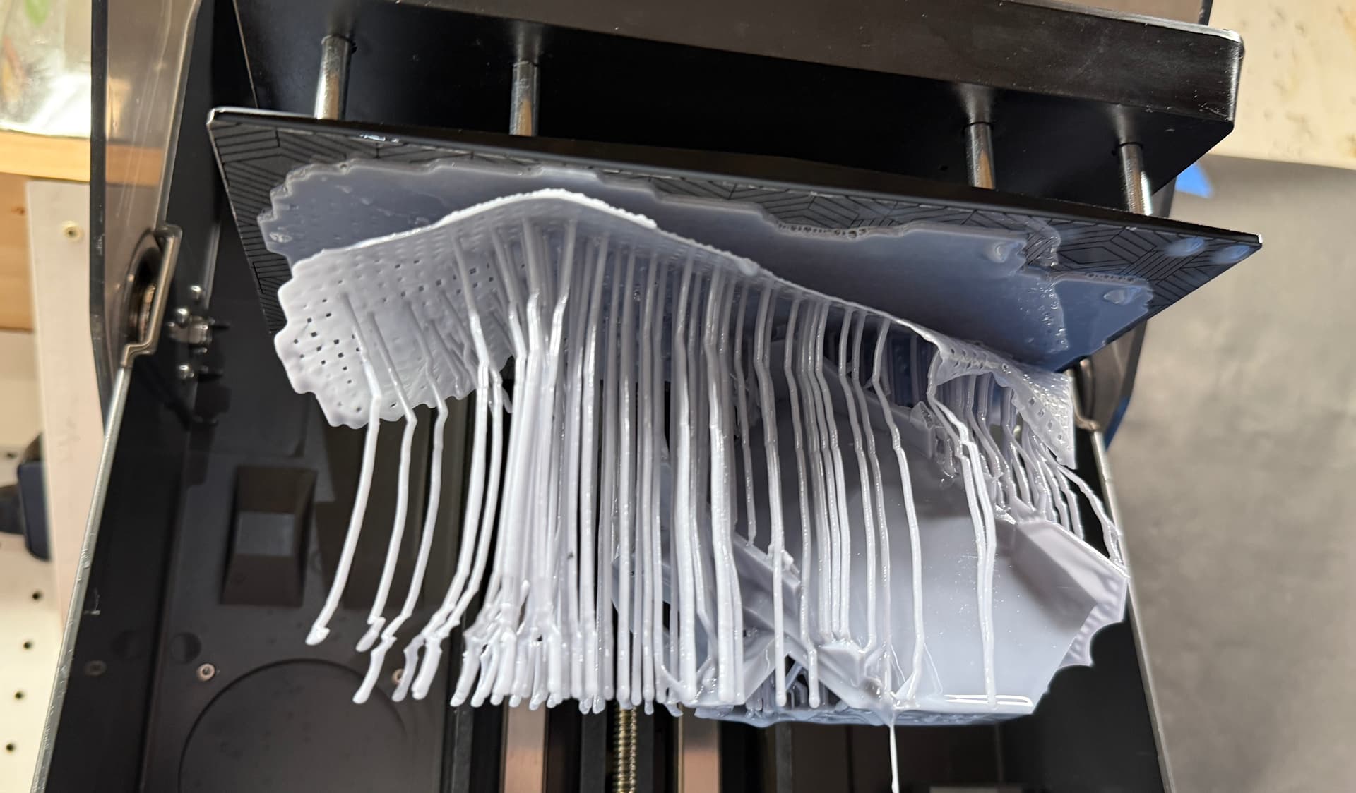
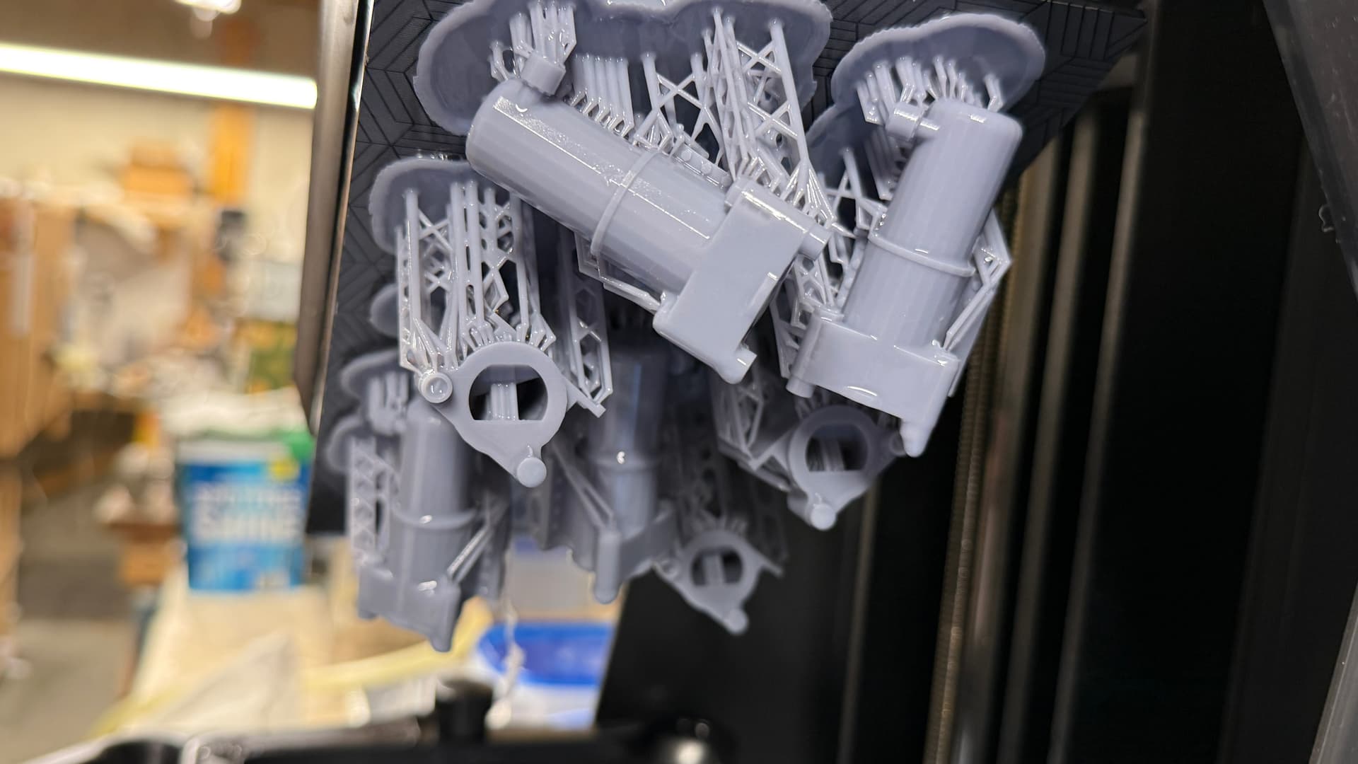
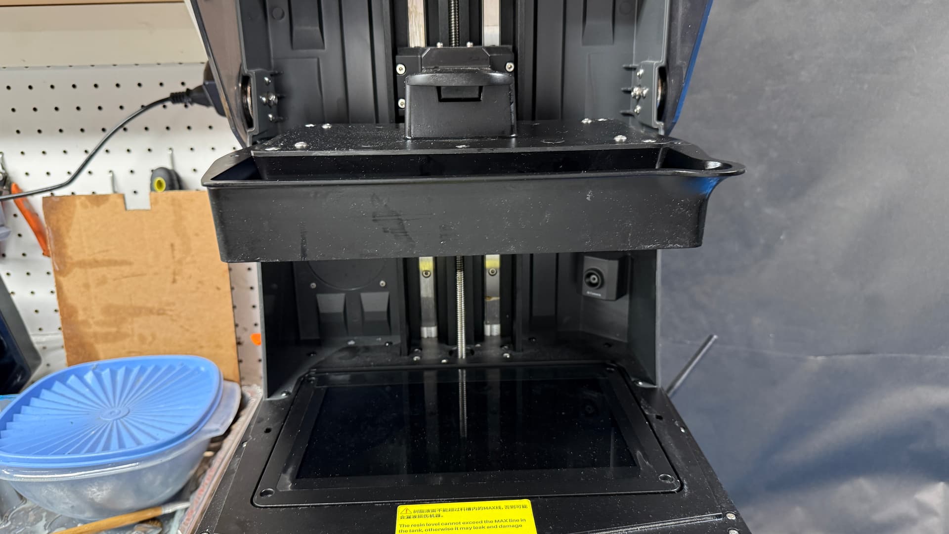
I put this new part on the printer late yesterday, but when I checked it after an hour and a half found that the print was failing. The base raft was delaminating. This was occurring in an area where the part was not even forming yet. The only load on the raft was the supports themselves. I’m going to change the PFA film at the vat bottom. There’s too much adhesive to the film. It should be releasing each layer without that much tension. When the raft fails, everthing that portion supports will be distorted, warped or worse. You can see the part beginning to form in the background.

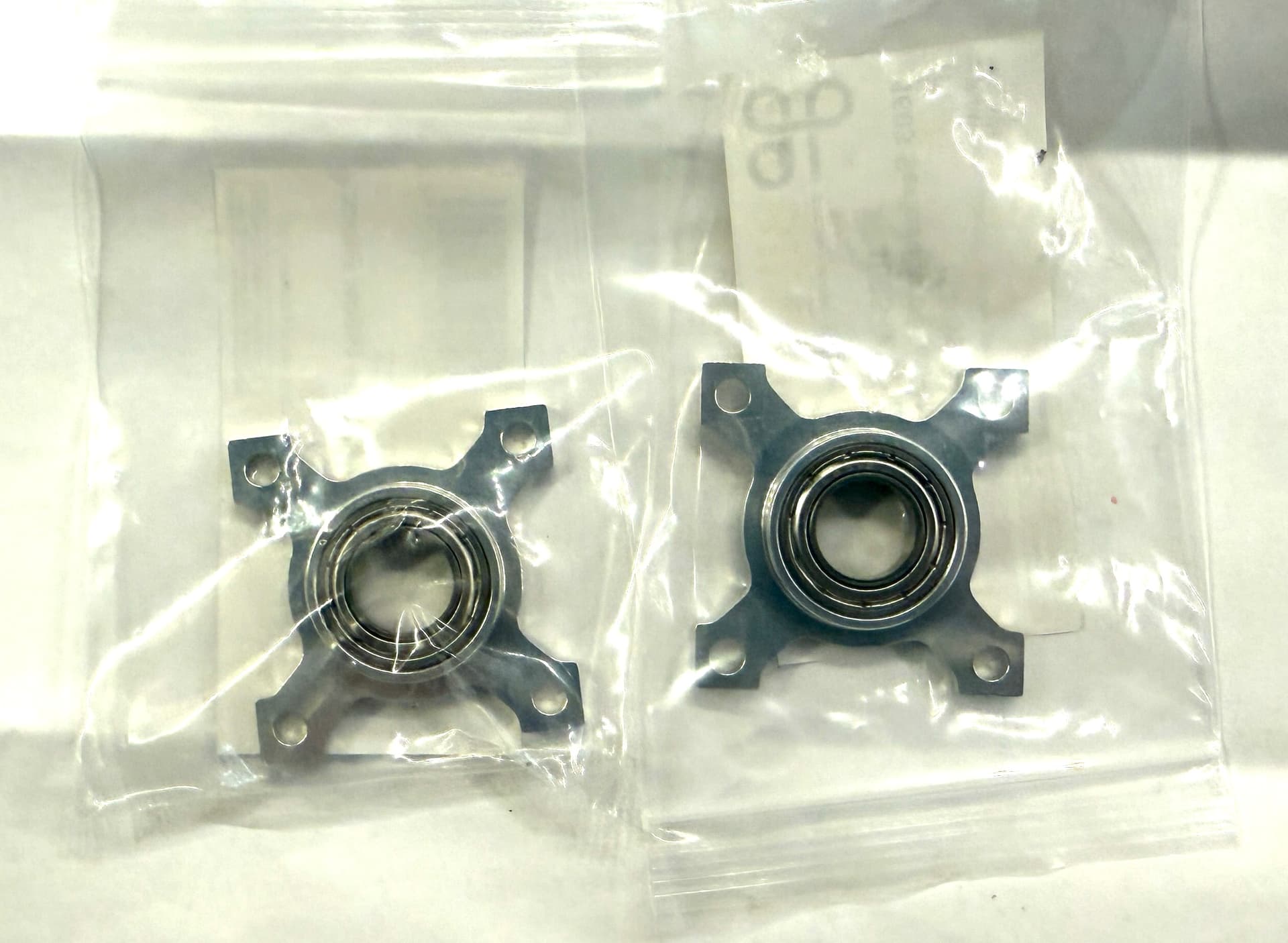
Meanwhile, I now have all the mechanical parts in my hands with the bottom main bearings arriving yesterday. These will fasten to the wood base with M4 screws.

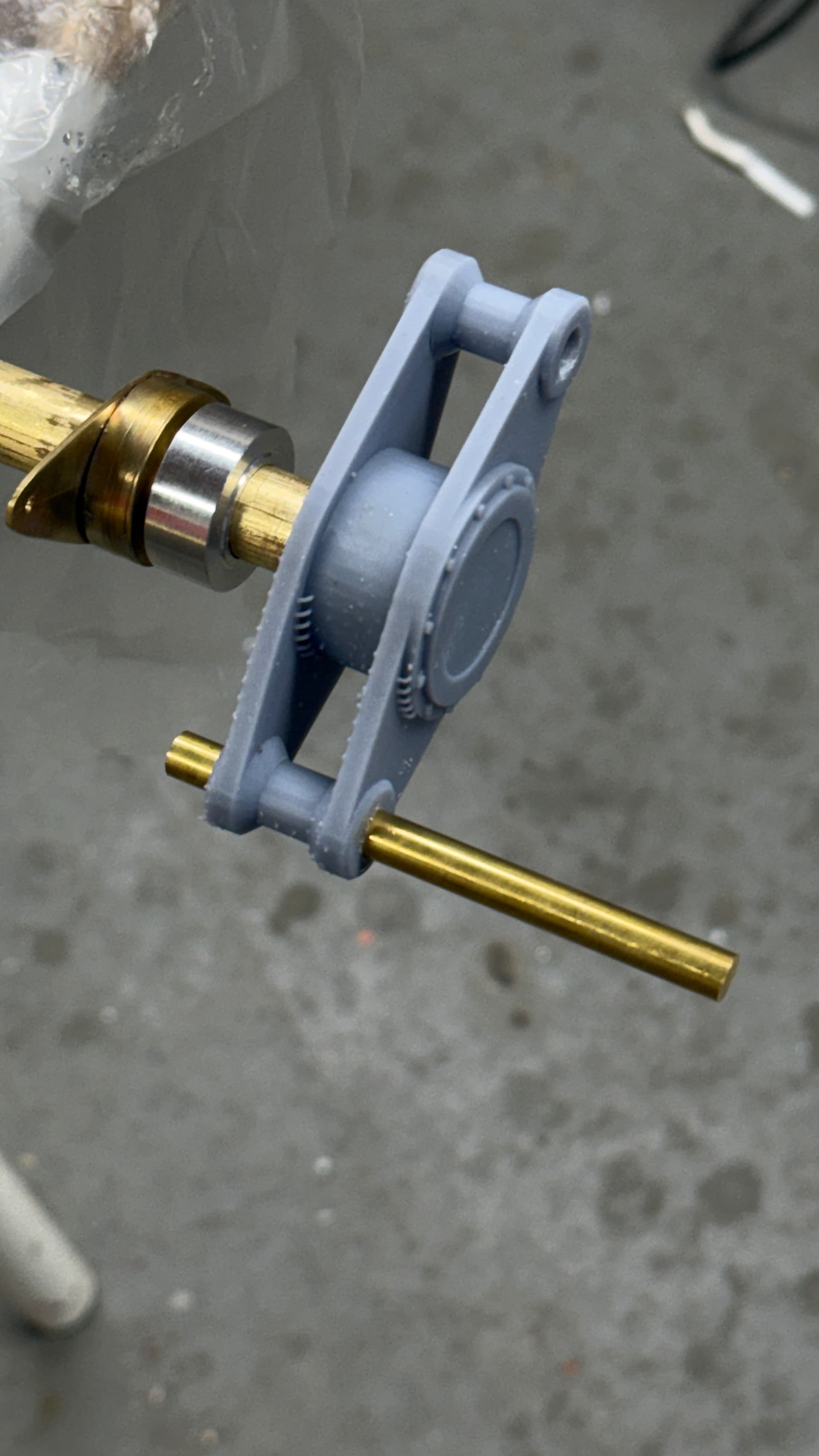
My test article to determine the right sized holes worked as designed. Here was the ram rod bearing fitting the 3rd sized hole perfectly. The nominal sized hole printed too small. That number is the 1:1 size that I needed to draw on the plans and then reduced to 3.12% in the slicer to create the hole size needed for the bearings. I was asked on another place I post “why can’t I just use a drill of the correct size?” Valid question, but there’s a reason. There’s only one place where an undersized hole can be correctly opened with a drill. All the rest are either blind holes or in parts with wall thickness that couldn’t stand the abuse caused by drilling. And the blind holes also make sanding to size hard to do. Creating the openings right the first time was the best approach.

Here’s the rest of the rotating parts sitting in their correct hole sizes. Note, none of them are the first measured size.

I continued designing the rest of the moving machinery. I got the cylinders drawn including their properly-sized opening for the bear sleeves and the hydraulic fittings for the piping and the mechanism that tracks rudder position for the indicator on the control panel.

The indicator mechanism is my invention. I have no good images or drawings of this contraption (yet) and had to use my imagination. I know what it’s supposed to do and understand where the rack should be, but what the actual gearing is or it’s sizes is a wild ass guess.

Just for laughs, I’m going to see if the printer can resolve the gears hidden within. If it doesn’t work, I’ll print without the cutaway.

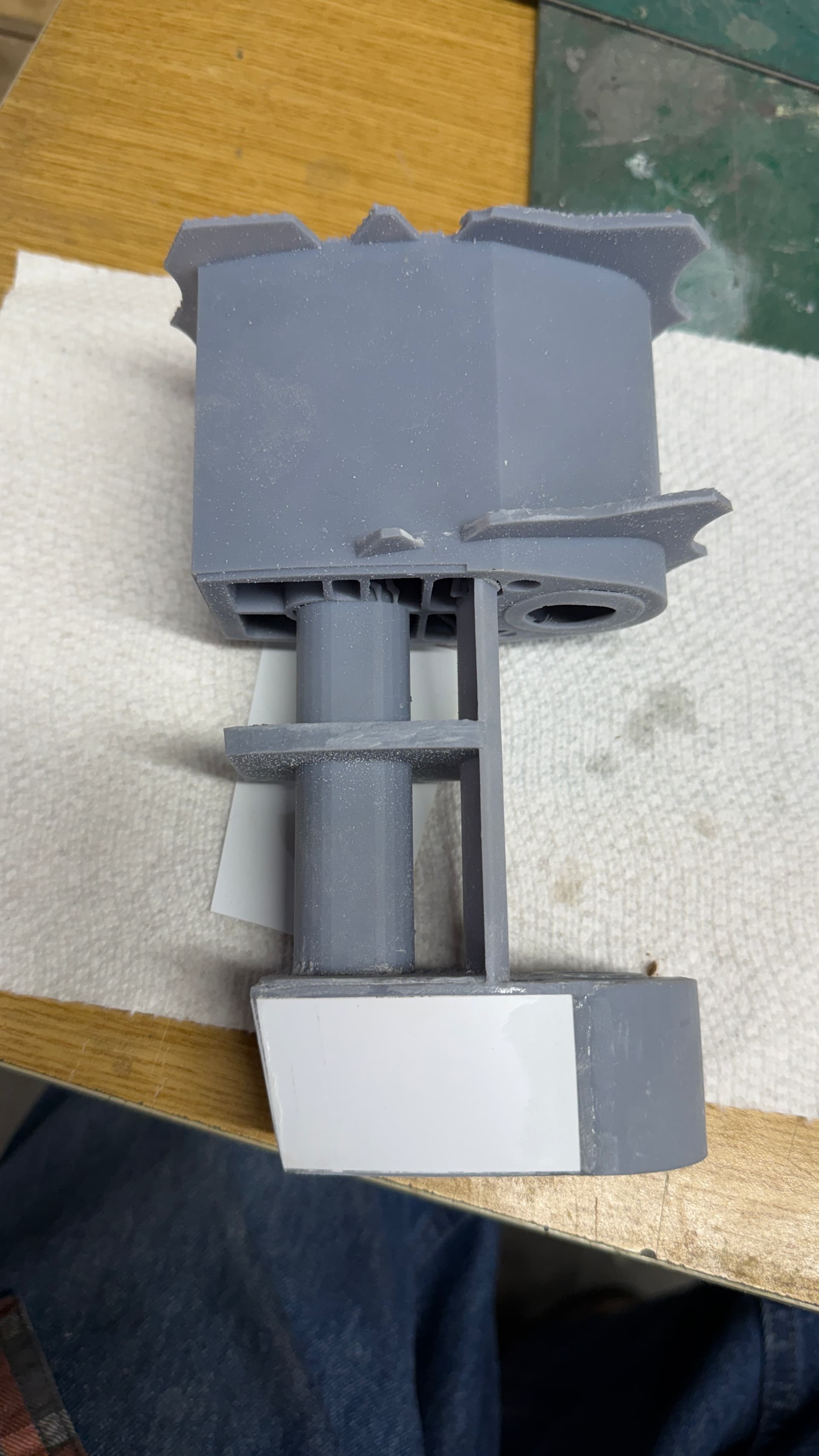
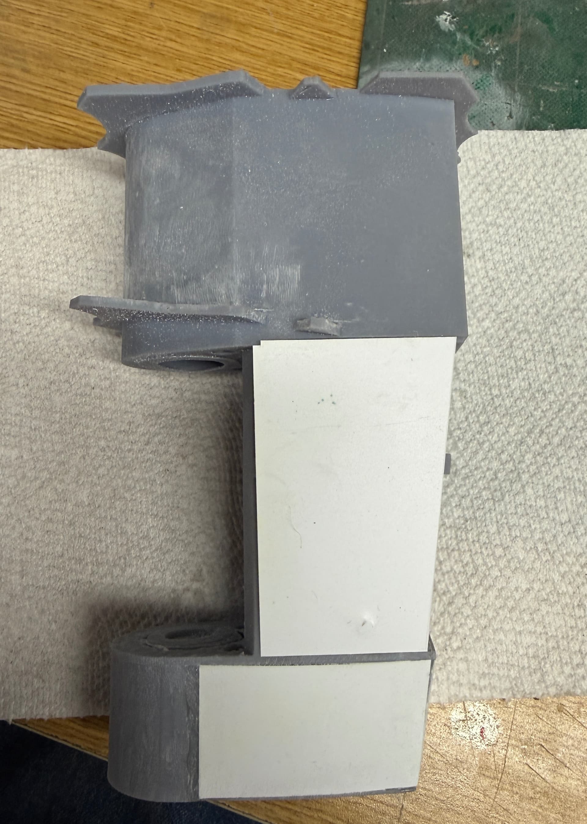
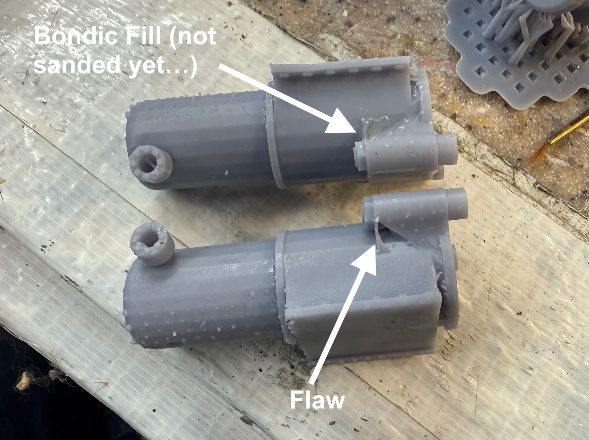
Yesterday, I took the rejected 1st attempt at a rudder hub and designated it as a test article and, in case the next print also fails, Plan B. It gave me the opportunity to see how the skinning technique should work. I used CA, but it wasn’t holding well and that’s a good thing to find out before the model’s sitting in a museum.

I used 0.020 styrene sheet, but the actual depth of the rabbets are 0.030" I will be getting some stock of that size. There’s not much of a radius to bend the sheet so even with the slightly thicker material, it should still hold. I also planning on using some small screws to retain the material, at least until the glue cures.


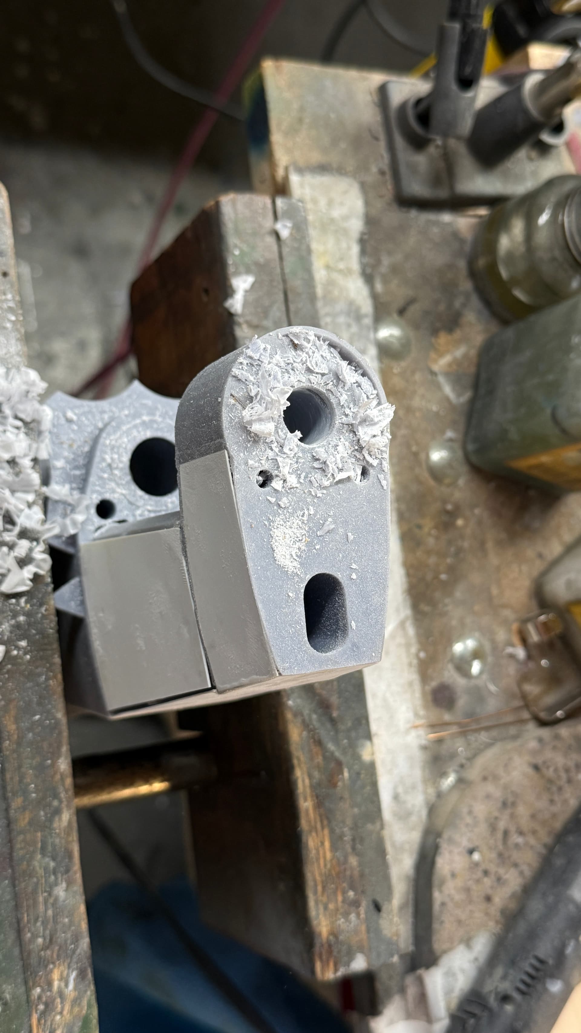
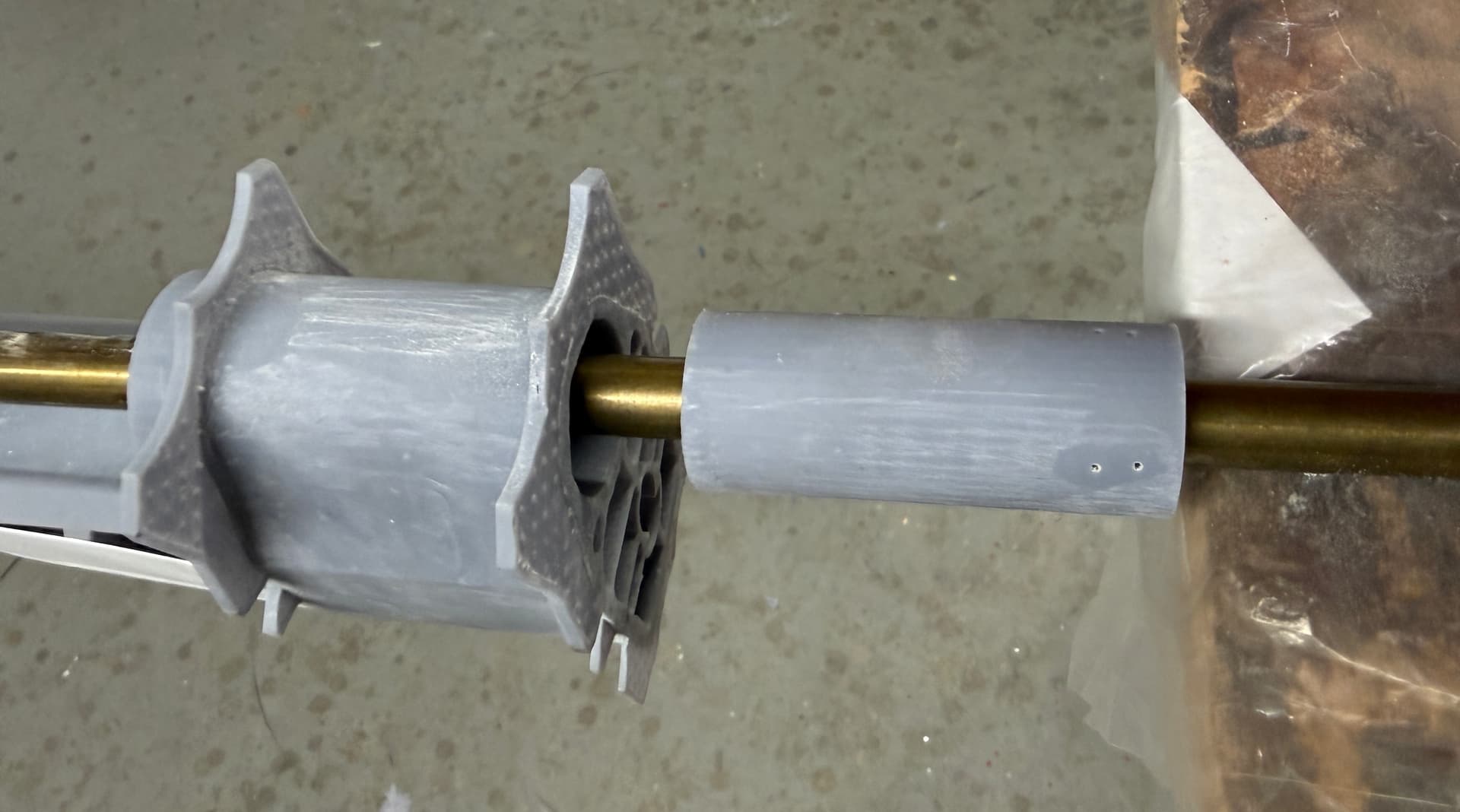
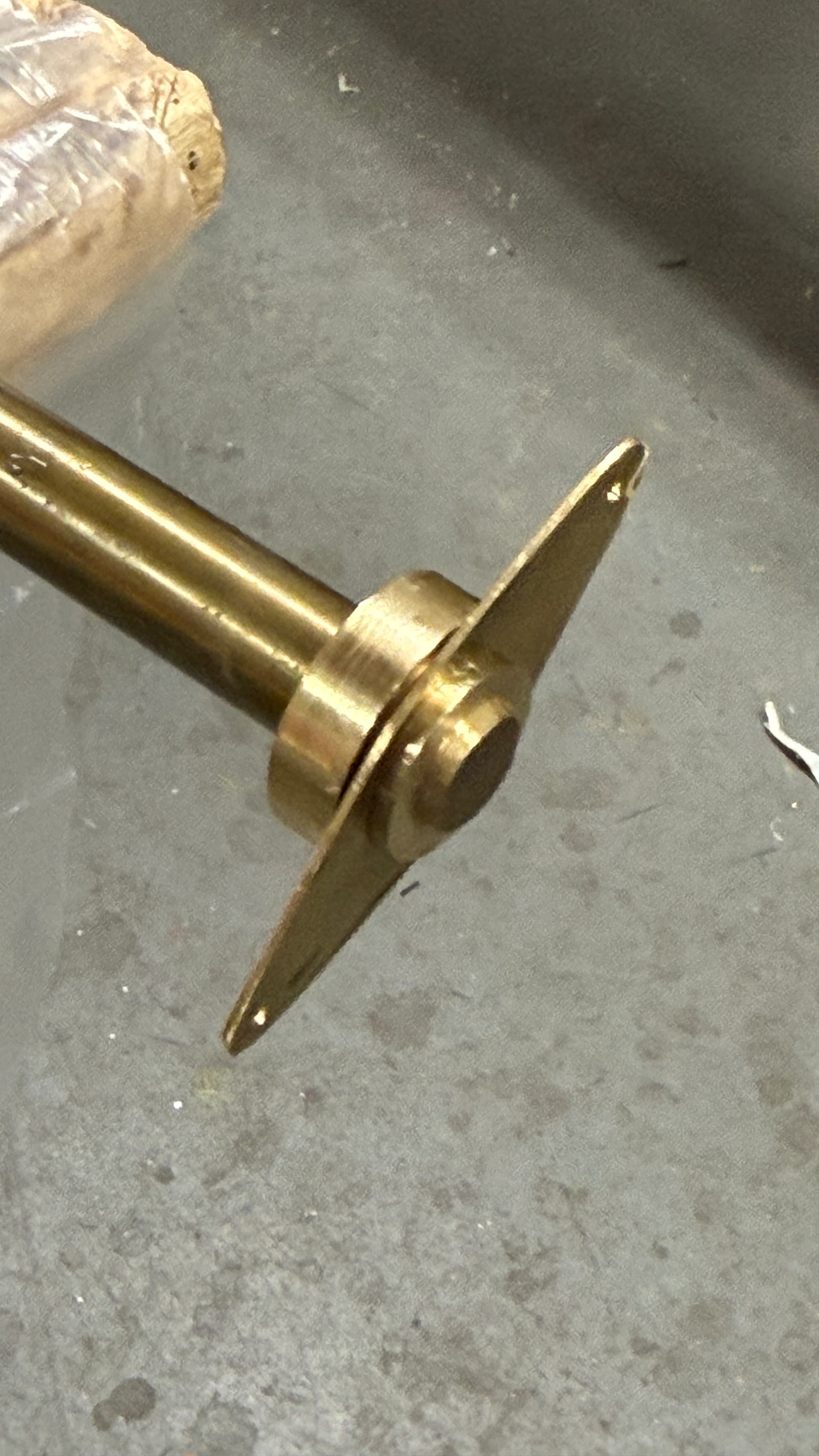
The Upper Rudder Stock hole wasn’t. It was a solid plug, so very careful drilling was done using a 1/2" brad-point drill while holding gently in my wood workers vise.

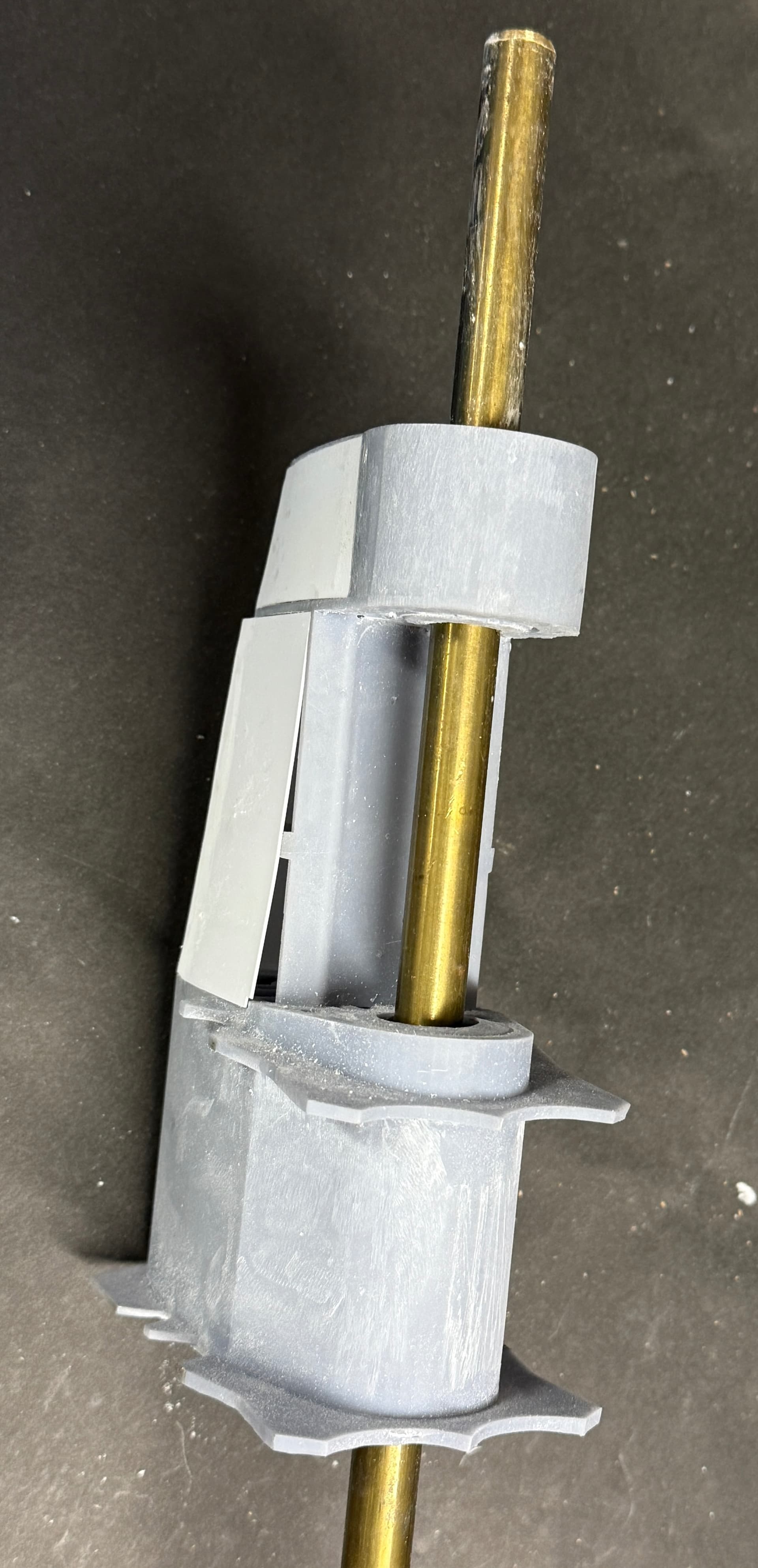
I’m using a 1/2 brass rod as the actual rudder stock, so the fit in the 1/2 hole was too tight. Because this shaft is actually going to be supported in ball bearings top and bottom, the holes through the resin part need to be very sloppy. It turns out that openning the hole with the largest metric drill I had—13.5mm—was the perfect clearance for the hole.

In this reject part, the bottom hole is way out of whack because the cylindrical center didn’t transfer to the slicer. I’ve drawn and will print a filler piece so this hole will be in spec as well.

This is a massive part and was just about the largest piece I can produce in my printer. Even will all the openings and hollow parts it used almost $9.00 worth of resin. The other large part will be the mating forging that forms the upper part of the rudder proper. I haven’t drawn that yet.

I will attempt to print the corrected part again on Monday, but if it doesn’t work, I can make this piece do the job.

I stil have to create the leading edge shape that goes on the angular flat side of the lower portion.

1 Like