1/35 CH-47D Chinook ... Finished, APR 2011

Ok, giving this another shot …

Been working on this one for a little bit now, but just thought that since I’m not too far along yet, I’d post things here too.

Here’s the inspiration … as some already know, I do most of my work using actual photographs as inspiration.

And the kit. Notice the sz 10 running shoe for reference! …

Couple of AM figures to go with it … Evolution/ MIG …

I also have Trumpeter’s modern CH-47D crew which will give me the crew + chief. I also have Eduard’s BIG ED PE set for this as well. I will also be acquiring some CMK figures shortly. The base will be done per my usual styrofoam method. The first picture says it all. That’s how its going to be built.

All in all, this will half 7-8 figures, the helo, and base. The helo when complete will be also be about 34" from rotor tip to rotor tip! I’ll need an actual hanger IOT store/ show this piece!

Here are the pilot figures that came with Trump’s “Modern US Army CH-47D Crew and Infantry” set. Pretty decent enough … to be closed up in the pit. Not all that great when set next to, say something like a Bravo 6 figure. (HEY VLADI! MAKE US SOME MODERN FIGURES!!!) :slight_smile: Figs have been assembled, primed, and faces begun. Since these pics (this morning) I’ve completed the faces, and begun painting the uniforms.

Trying a “new” method of pre-shading. Worked well for some figures that I just finished…

While the figures were drying, I wanted to try and tackle the task of reshaping the rotor blades. The blades right out of the kit are shade PERFECTLY for a bird sitting on the tarmac. Drooped very nicely. I thought about just turning them upside-down, but they looked funny. Not like the slightly tilted up, but straight blades seen in flight. I took all the blades and put them into a large cup and started running hot water from the tap. I let it over flow so that the water would continue to stay hot. Mean while, I began to boil some water. After boiling, I slowly poured the boiling water into the cup, letting it sitting for only about 2-3s before removing the blades. I had a station set up next to the sink w/ a sheet of plexiglass and some weights. I put the hot blades on a papertowel, placed the glass on top, and then added the weights. After a few minutes of cooling I had straight blades! YEA!!! I then dipped the rotor head end of the blade into the still hot water IOT add in that slight bend/ tilt up. Hopefully, you’ll be able to see more of what I mean in later updates when I get the rotors built.

I also started working on getting the pit together. Kit pieces seem nice enough. Can’t wait to get it primed and painted so I can add in the PE parts. I added some pieces from the spares box to the back side of the instrument panel to add detail and interest. This will be visable through the windshield and lacked any detail before. Since these pics I’ve added in some wiring, etc to add even more detail.

My plan is to get the pilots completed, get the pit primed/ painted and PE’d, and get started on detailing the interior fuse pieces. But mostly I want to get the pit completed.

A little paint on the pilots, but no where near done … I goofed on the eyes, and am considering redoing the faces, but then again … they will be closed up…

A little wiring behind the main instrument panel.

I had to add a small bulk head to the underside of the floor as you can see this part when the canopy is added … plus a little wiring.

And, a quick mock-up of the pit to check fittings…

Got a little mock-up/ fitting work done on the other figures “involved”. I’m not too in a hurry to work on these since they’re going to be set outside of the bird. However, before I can work on the crew chief, I’ve got to make a mold of his head/ helmet for another build. I’m also considering making a cast of the rest of him since the Hook has a crew of 4x. Leave it to someone like Trump to only make 3x of the 4x crew members for a kit … they probably have the 4th in an unreleased kit some place!

Disregard the Soldier carrying his buddy. They come w/ the Trump crew set and I thought about using them, but I’m going to be opting for a couple of CMK figures instead.

Anyway, here’s the other figs…

Also got a little more work done on the pilots. Visors and mics done. Just need to darken and Future the visors and then finish up the painting on these. Too easy for a night or two of work …

Here’s one side of the cargo seats. Not 100% complete. Won’t get there until some paint is done. Was thinking they needed a little more texture to them, but whatever. They’re going to be closed up.

And a little work on the inner fuse. Call me lazy for not wanting to get straight to priming and painting, but I’ve decided to punish myself by doing a little more work on the inside. The fuse itself is marked/ scored to “show” the fabric-lined interior, but it just doesn’t look like the reference pictures I’m looking at. So, I’ve added some styrene framing members and will roll out some room temperature curing clay, cut squares to size and place them inside along the walls and ceiling. I’ll then “draw” patch lines in the clay w/ some clay tools. Should look much better. Good thing is, the first framing piece helps to hide the joining line from the main fuse to the tail fuse.

Here are the panels that I’ve gotten done so far … and an up-close look at a near-finished panel w/ the original. I think the biggest difference is the look around the window slots … I think it looks MUCH more realistic!

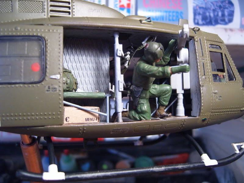
The interior padding is being done w/ Milliput. This is really this first time that I’ve worked w/ it and I’m finding that it’s really easy.

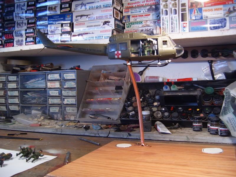
I began to notice the added weight to the fuse half and instantly started thinking about the internal frame to help carry the weight since the helo will be hovering …

Here’s some work/ thought on the frame as of right now. This is not a tried and true method, but its got to work the first time. Once the fuel tanks are added on to the fuse, there’s no turning back. Anyway here’s what I’ve got so far …

On the inside of the tanks, small notches were cut out for a large dia rod to slide in.

The rod, in place, was filed down w/ a round file at certain spots and a smaller dia piece was glued into place. These cross-pieces correspond to a hole in the fuse half.

Next, there will be an even smaller dia rod that will run under the floor inside the Hook, through the wall and slide into the cross-pieces attached to the larger rod.

Total, there will be about 4-5 rods running through the floor, going out to a large rod on each side. This rod comes out just to the inside of the rear landing gear. It will/ can be seen from the outside, but I’m hoping to make this minimal and I hope it won’t be an eye-sore. The weakest part I see to this whole thing is the bend from where it comes out near the landing gear to where it goes into the building and into the base. I’m thinking about using a steel nail, heated and bent to shape for the connection. Since these pics were taken, I’ve decided to remake the frame using brass tubing so that I can solder the joints.

The following images will give you an idea as to how I plan to build in the frame to the A/C and then into the base.

In the first pic, you’ll see the framing as I see it running through the fuse. 2x rods will run the length of the fuse from inside the external tanks. Connecting those to will be a series of 3-4-5 smaller rods running underneath the fuse floor.

In this pic, this is how I plan to have the framing coming out of the A/C near the rear gear, through the building and into the base. I think this idea is going to be pretty stable.

Here are the completed pilot figures. Not the greatest work I’ve done, but then again, they will be closed up in the cockpit.

And updates on the bird. I started adding in a little PE to the rear ceiling, but as par w/ the kit, the PE set fell a little short. Here’s what the PE set gave me …

So I added in a small scratch-built frame/ box to help tie things in …

… and here’s what I came up with …

Next I started in on a little piece that probably won’t be seen at all, but I know it’s there. This is one of the pieces that I was surprised wasn’t in the kit. It’s all part of the aft engine/ tranny. But b/c the piece wasn’t there, I had to go spares huntin … I ended up using a main landing gear piece from Mono’s B-17G w/ a little copper tube stuck on it. I think it’ll work …

Spent a good bit of time during the Memorial Day weekend away from the computer, and I would have liked to spend more time at the bench, but I was pretty please w/ work that got done.

I spent most of the time trying to finish up construction of the interior … didn’t get there, but got a lot of framing in and finished.

Here’s the scratched ribbing done for the interior near the rear cargo ramp. This will be the majority of the interior that will be seen. Framework was done with sheet styrene, using a contour gauge to get the right angles and curves. I was pretty worried about how this process would go, but it ended up being pretty simple and only took me the better part of one afternoon.

Framing cut, drilled, and ready for gluing…

Framing installed …

… and compared to the OOB half … (Sorry about the focus…)

Next, I cut thin strips from sheet styrene IOT make the framing for the interior ceiling. This is really more to help me put the Milliput “padding” in later …

… AAAAAnnnnnnd … pretty much an “overall” shot to sum up this update.

A lot more work went into this update than it looks, but it’s hard to get many pictures of something that looks all the same. Anyway …

Here’s the first section of the ceiling panel and how it will look w/ the fuse. The “cutout” on the small panel will be for 1x of the Hook’s 7x first-aid kits.

Here’s the ceiling section completed … minus the small panels (they look the same anyway) … and a close up.

And here a shot of the inside w/ the fuse mocked up. A little dark, but you get the idea.

This brings this build “up-to-date” for the moment. Next, I’ll be finishing up the cargo seating and the frames for those and then getting them dry-fitted. After that, I’ll be finishing up on the “plumbing” in the rear ramp area … then I should be ready to start in on the interior painting.

Thanks for checking it out … and as always any and all C&C welcome.

Hi Scott,

That looks like it will be fantastic when complete. I like the extra padding you added. That last picture really sells the depth and texture, much better looking then the flat plastic was.

Will your support rods be continuous from the helicopter into the base, or will you be slotting them somehow to allow you to separate them? One set slightly smaller in diameter than the other?

I look forward to seeing the next installment.

Paul

Hey thanks, Paul.

I may have said it before, but I’ll clarify … Yes, I plan on building the support framing for the helo and base so that it can be separated. I will most likely, as you said, have a smaller diameter rod placed in the separation so that the pieces simply slide onto one another. Thanks for checking things out…

She is looking great Scott. I really like the added padding. Great dio idea too. She must weigh a ton with all that putty on the inside though. That could be an issue when you work up the support rods.

Some impressive extra detailing going on in that Chinook!

Thanks for all the comments guys. As of right now, the bird is about 30% complete and there’s literally 1/2lb of Milliput in there. Good news is, there’s no more putty that’s going in. I’m done w/ that part. All that’s left are the kit parts, a little scratching, and paint. Not much else to add weight. Another thing that I’m considering is almost filling the rear engine housing w/ something to help counter the weight that will be hung out there on the frame … keep things “centered” over where the frame will go in to the base.

What do you guys think?

You say you have a half pound of putty in the fuse ahead of the rear wheels, I’m guessing you’re going to need almost a pound of weight behind the rear wheels to counteract the moment arm that the fuse makes up. You’ll have to decide if the model can handle that kind of stress but I can’t fault the logic behind trying to balance it out. Good luck , that’s an amazing build so far!

That’s a good point on the weights. The good thing is that the frame will be exiting the airframe just forward of the rear landing gear, from the external tanks. This means that I’ll have about 3-3 1/2" to the very rear of the fuselage. Hopefully, this will give me a little leverage when adding weight back there.

I’m heading to the store here in a minute to check out fishing weights and such. I don’t know if I can buy birdshot by itself or not. Maybe I’ll use BB’s … but I’d rather use lead weight.

I’m going to be building the entire frame before I build the building and base. This way I can check the balance of the helo on the frame. As long as it somewhat supports the A/C, it should be good, because when I slide the tubing/ frame into the base that will just add more rigidity to it.

Let me know if that’s making sense or if I’m just talking crazy …

Thanks again for checking this one out and for all the ideas. I appreciate it.

I’m not sure you should add any more weight at all. As long as the support rod inside the fuselage is long enough, the balance shouldn’t be an issue. If you extend the fuselage tube the full length of the side tank, it should be good. I did a similar set-up for a flying DustOff Huey. Granted, it wasn’t as heavy, but it did have a bunch of resin and it was pretty heavy for it’s size. I sunk and secured a piece of copper tubing diagonally across the fuselage from one side to the other. Then used a smaller piece of tubing that slid inside of it attached to the base. It worked really well.

The support pole later became a tree.

I’m not an expert, but I agree with Gino, skip the extra weight in the back. I suspect you would need quite a lot to counter balance the amount you’ve got running the length of the fuselage. The hollow tubes should be able to take more weight than you’re going to be putting on them before bending.

Paul

Ambitious project!

I admire the scope & scale of this endeavor, great extra details as well. The Millput is heavy by design, long as the base is sturdy enough weight should not be a issue. Looking forward to more WIP’s![Y]

Thanks for all the thoughts guys. We’ll be sure to let you know how things go.

Gino, nice job on that MEDEVAC build.

Hello Scott,

A very nice and ambitious build. Looks like it’s going really fast, too. I’ll be watching, good luck with your project, and have a nice day

Pawel