really enjoying this build builder 2010 . see you when you get back
Well Steve… I’m back. Had a very nice trip back East. The first weekend was so cold in State College (Penn State) that we had winter coats, hats and gloves. By the end of the week the temp was in the low 90s. Ah… Spring. Yesterday and today the Louisville weather was absolutely perfect and I got another color coat on the Ford Fairlane model and then got back to work on the Essex.
I ordered the threaded tubes, nuts and bolts from Grand Brass Lamp Parts on the web. While I didn’t buy the pedestals from them (bought them from Totalnavy.com), they had the same turned brass parts for less money AND they had many more different turned objectst that would make very nice ship pedestals. These are a 28 thread pipe thread that’s specific to lamp construction. It’s a straight thread unlike pipe threads which are tapered, but you won’t find 1/2-28 threaded nuts at Lowe’s. You’ll need to get them at a lamp supplier. But the tube is designed to fit the pedestal perfectly.
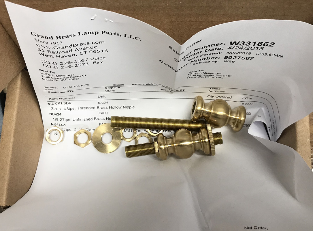
These parts are not particularly expensive.
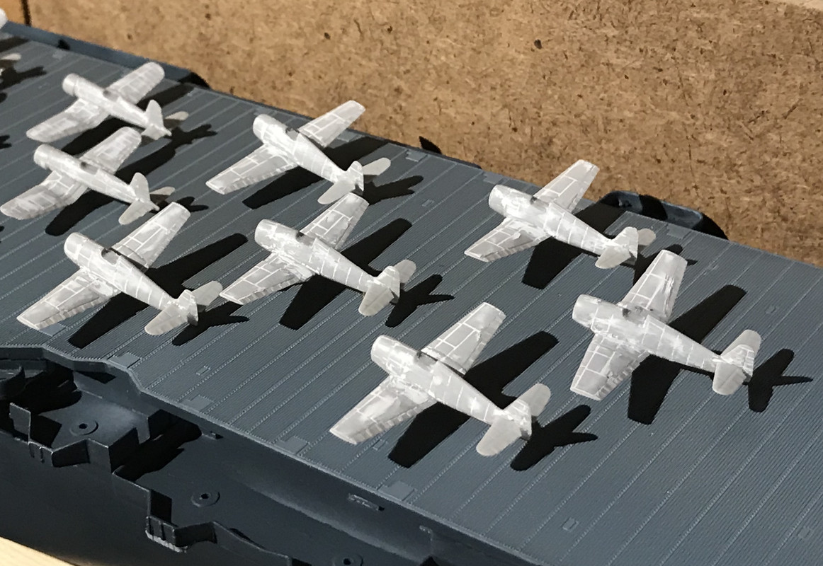
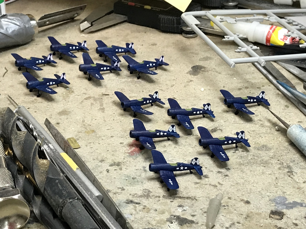
Then I got back to work on the Hellcats. I sanded off all the excess filler that was not totally cured after sitting for 13 days, and assembled the parts. Got almost finished putting on the landing gear and got drawn away to go with our oldest grandson to get fitted for his Jr. Prom tux. His mom was out of town, so I’ll finish the Hellcats tomorrow and paint both them and the Cosairs. By the end of the week the air wing will be complete and I’ll be back to work on the ship itself. I should be getting the finished plank any day now and prepare the lower hull for mounting. I think I want to put all the gallery guns and railing AFTER the ship is mounted to the plank since it makes it very stable. That’s how I did it with the Missouri and it worked pretty well. Once I get the plank and get the final dimension on the perimeter rabbet cut that will support the clear case, I’ll send those measures off to the plastics shop and have them cut to size.
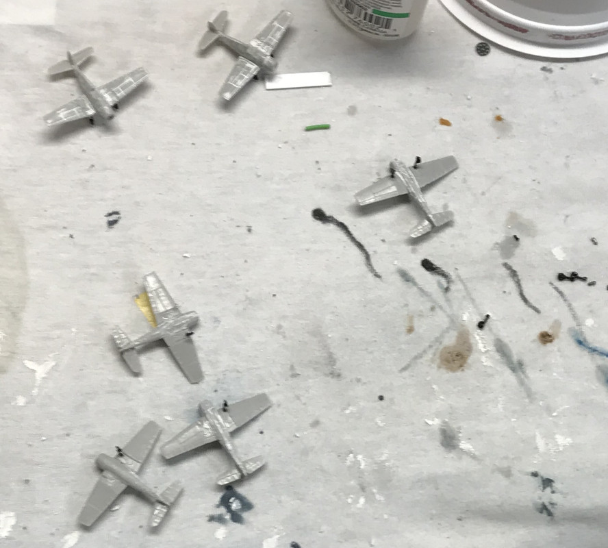
Notice, I did not fill the seams on the horizontal stabilizers. Enough was enough!
Yesterday, I finished gluing all the Hellcats together. Only lost 2 tail wheels…
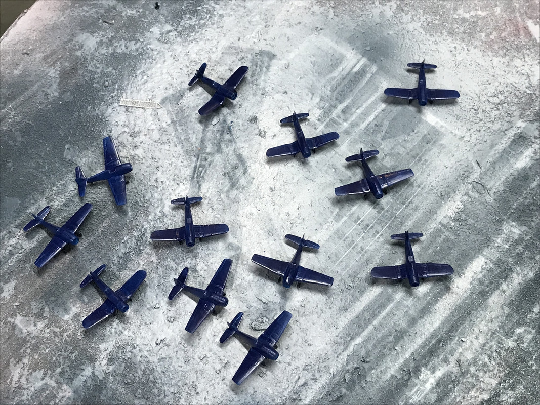
And then today I air brushed the Vallejo Dark Sea Blue. Took several light coats. Mixed the paint with about 30% (guesstimate) of Testor’s Universal Acrylic Solvent.
Tomorrow I’m tied up and will not get much (if any) shop time, so the next work session I do have I will add the interior green, and flat black detail painting and start decaling. That should take a couple of days and then it’s back to the rest of the ship. The plank is on its way and I may have to wait a bit longer to get the lower hull finished. I have other projects to work on during the wait. Can’t order the plexiglass until I have the plank to take as-built measurements.
BTW: I ordered and received Bondic UV-cured adhesive from Amazon. I wanted to see it if would work for the landing gear gluing. I arrived when we were away so I was able to try it out yesterday. It does work, but it needs a roughened surface or it doesn’t hold so well. It does cure quickly and stays gel-like until you shine the light on it… which is convenient. I wonder how well it will work in holding on PE railings? Only restriction is the light must be able to get to the gel. In a totally closed joint it will not work.
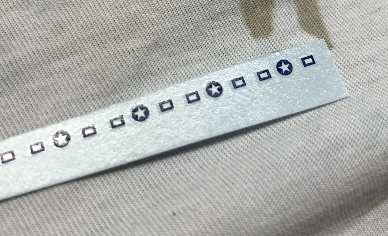
The day started by painting the details on the 12 new airplanes (black tires and engines, plus interior green cockpit area). I then started the decaling process by putting on my custom tail design on the Hellcats and began the stars and bars decaling. I got one plane complete and started one more, and then broke for lunch. The Trumpeter Hellcat and Corsair decal set has the stars and bars as separate decals. I know why they did this, but it wasn’t nice. The earlier planes just had stars and then later added bars so having them separate let you choose. BUT… it makes putting on the decals soooooo much more annoying. I found you have to trim the circle very tightly on the the sides and do the same for the bars mating sides so they’ll nestle in correctly. I used MicroSol to get everything settled down.
This close up shows the large clear area surrounding the printed area and this makes getting them close impossible. If you put on the star first, let it totally dry and then added the bars so the clear part overlaps the star, it could work, but it would also be a pain. Trimming close works better.
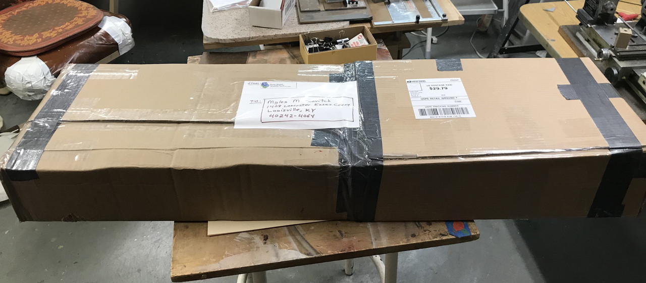
Then, during lunch, the mailman delivered my oak plank from my close friend in Albuquerque. It was packed within an inch of its life and came through unscathed.
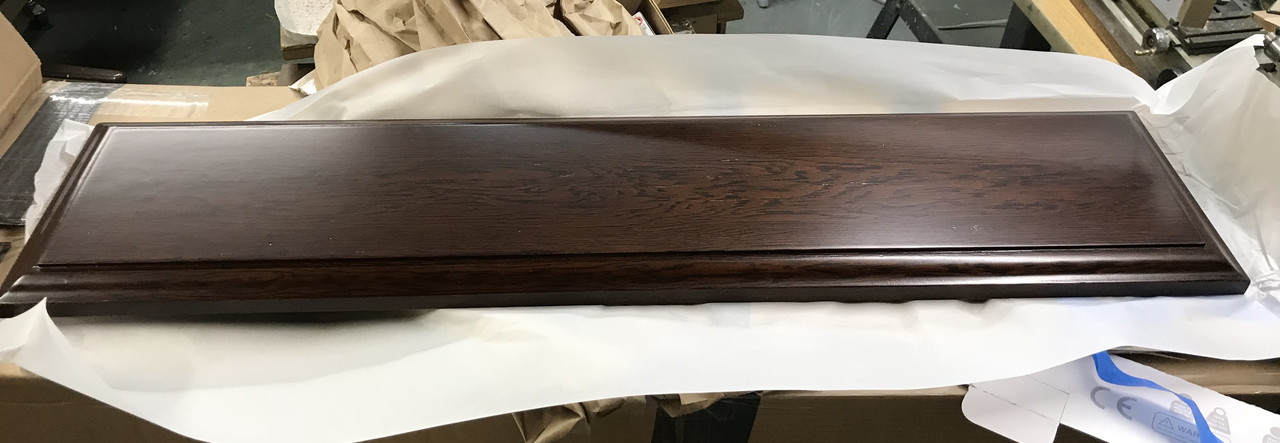
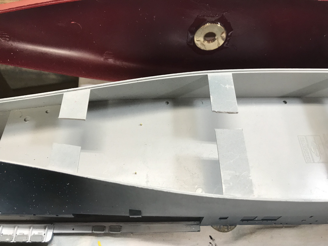
I masking-taped the top and bottom areas where the drilling would take place to prevent break out when the drill comes through. I located the center and drew a center line down the back side. My mount holes are to be 7 inches apart and I laid those out also. But they needed to match the ships layout and I couldn’t drill them at the same time (safely) so I drilled a 1/16" holes in the hull at the proper locations and used a transfer punch of the same size to locate the two hole locations on the plank’s bottom.
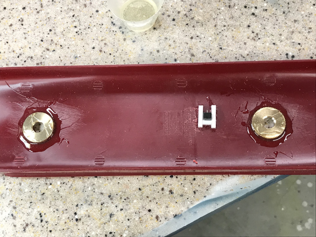
The bottom needs to be counter-bored so there’s room for the threaded pipe and brass nuts and this is done with a forstner bit. It has a pip in the middle which then serves as the starting point for the brad point bit to make the clearance hole. I put it all together to test the fit and it lined up nicely.
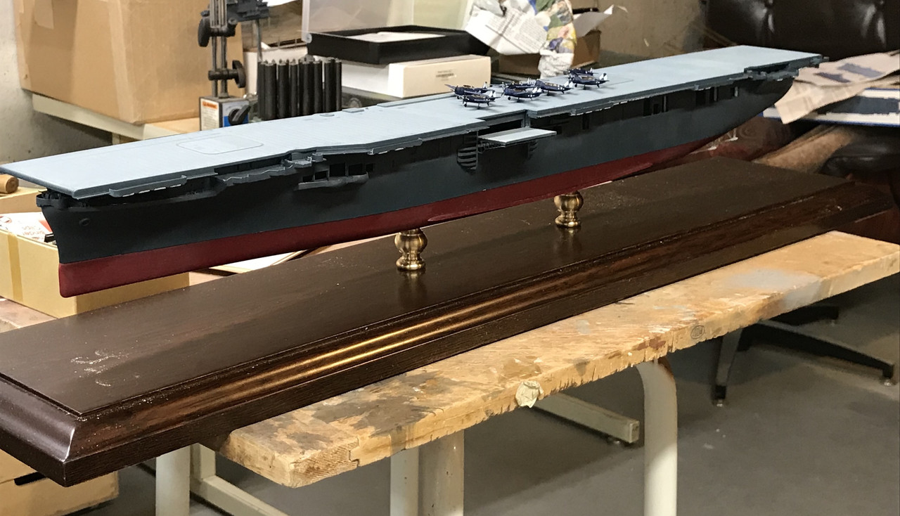
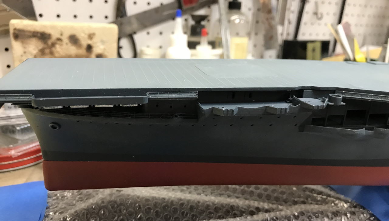
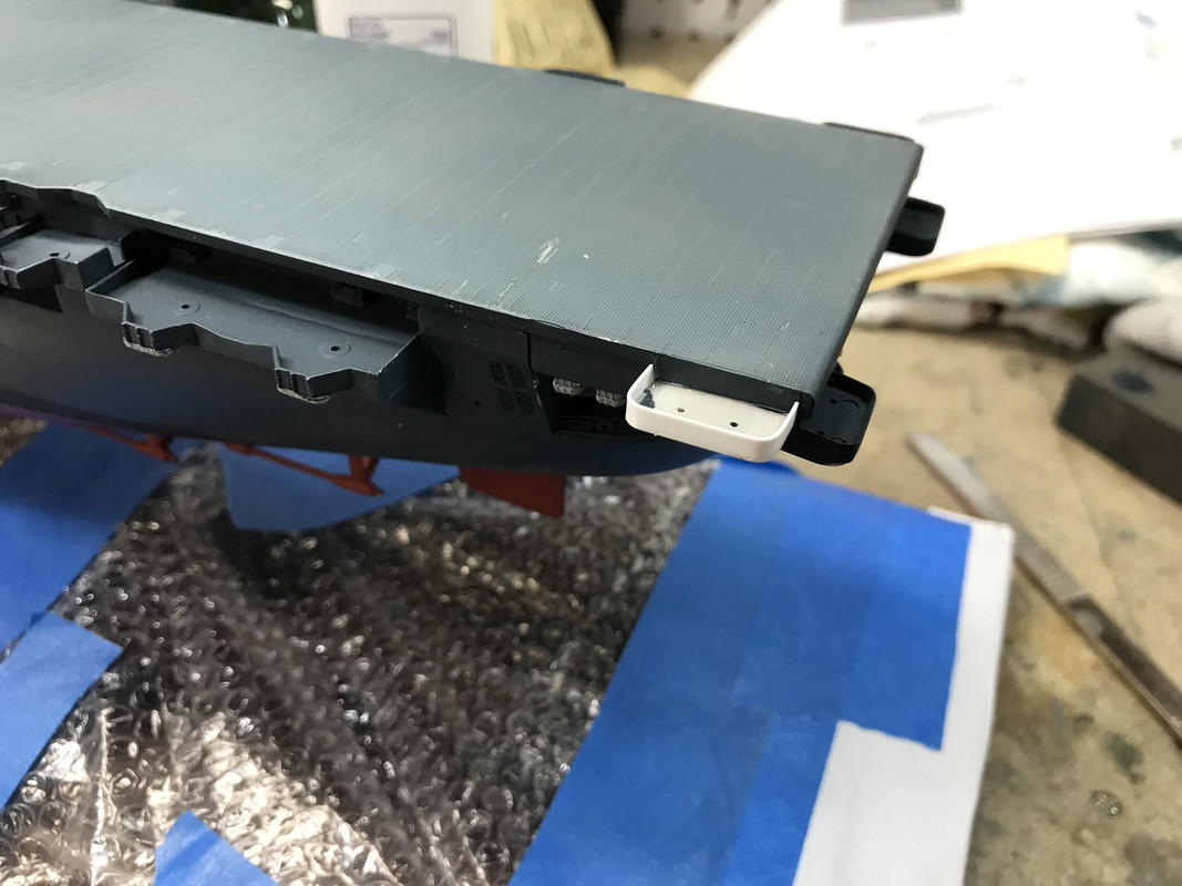
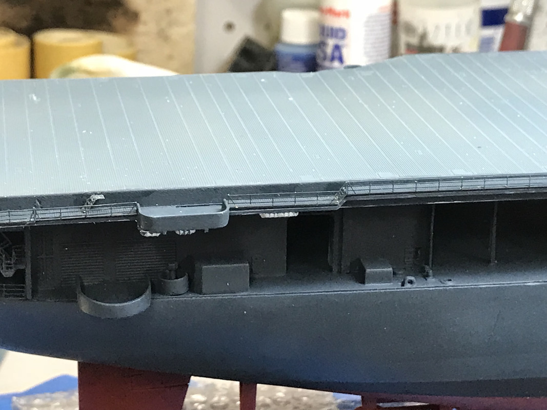
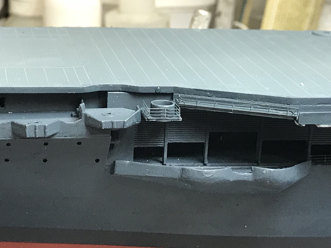
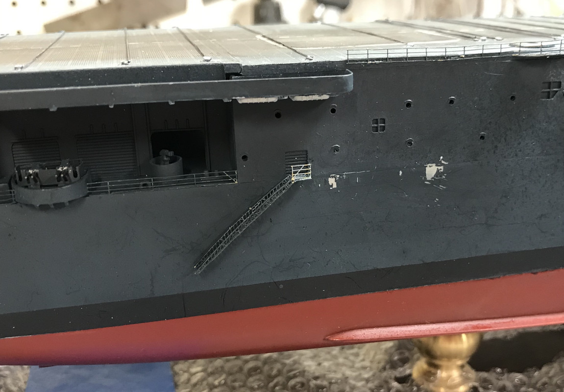
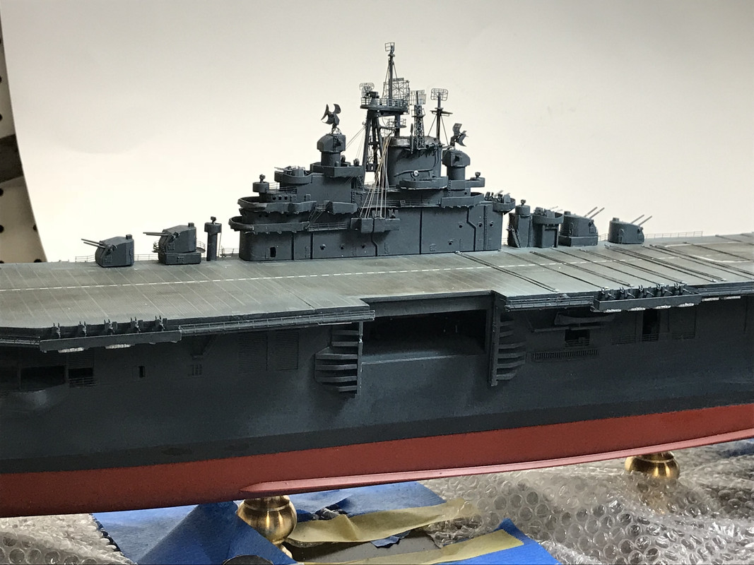
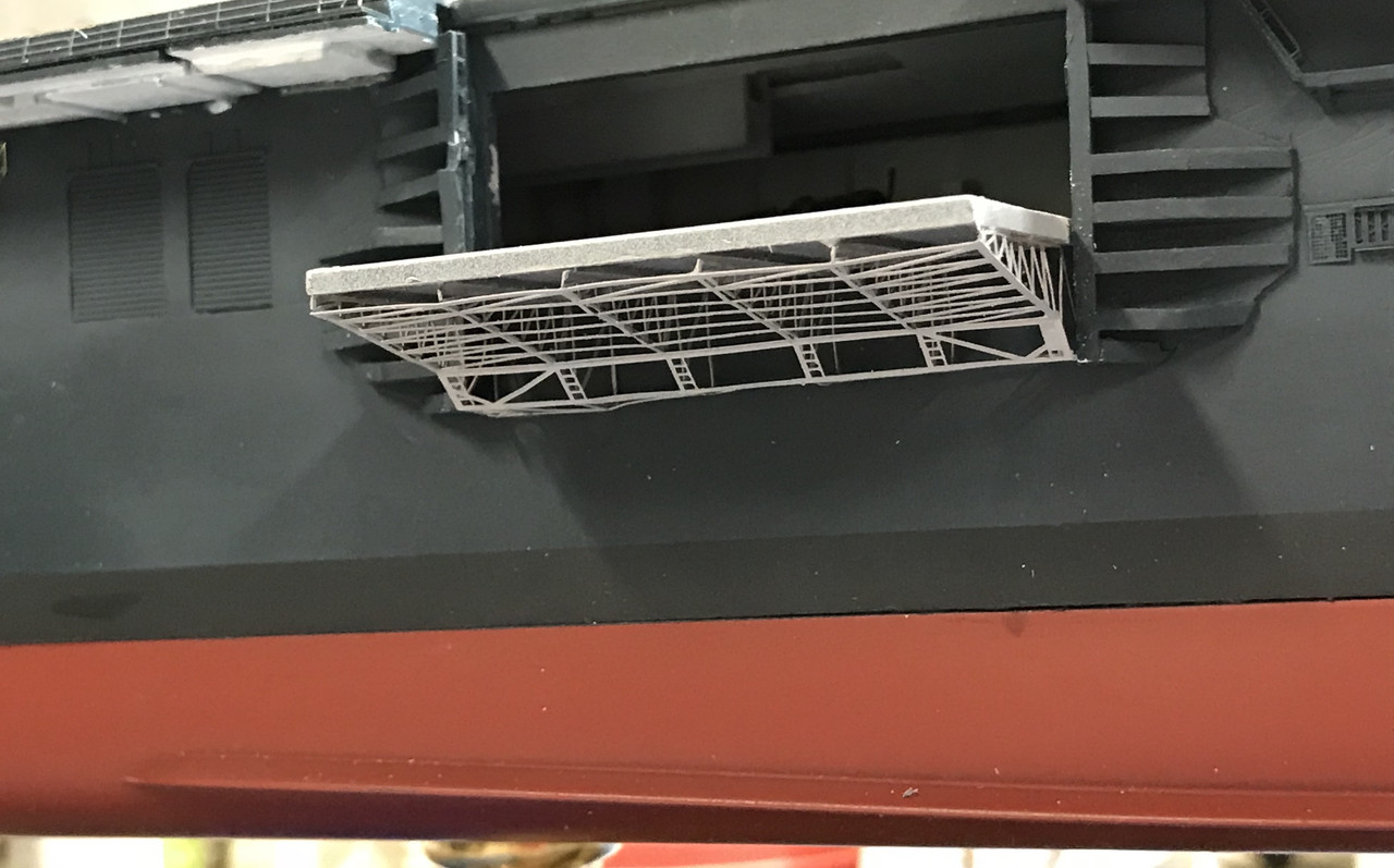
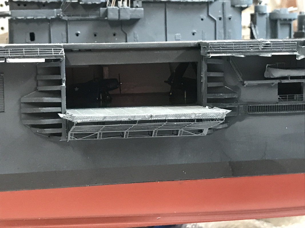
The upper and lower hulls are NOT glued in this pic, nor are the fasteners epoxied inside the lower hull. I was able to take final measurements for the plexiglass and I’ll order that tomorrow. The I noticed how close the side elevator is to the rabbet edge that holds the plexiglass. I put a piece of flat stock in that location and found that there was about 1/16" clearance. Whew! Then… while driving my grandson home from his piano lesson and describing this new addtion to him while he looked at the pics, I remembered that there are PE simulated safety nets that go on the elevator’s outer perimeter and they will exceed that 1/16".
What to do? The pedestals are wider than the holes with enought material that I probably can elongate the holes in the hull enough to push it slightly off-center and give myself enough clearance to add the elevator nets. When I initially meausred for the plank, I guesstimated where that elevator was going to fall and thought I gave enough addtional clearance. It will work, but not without a little anxiety thrown in.
(Pictures weren’t loading today… Don’t know why… Post-Image downloaded pics, but didn’t display them. When it starts working again, I’ll edit this post to show them.)
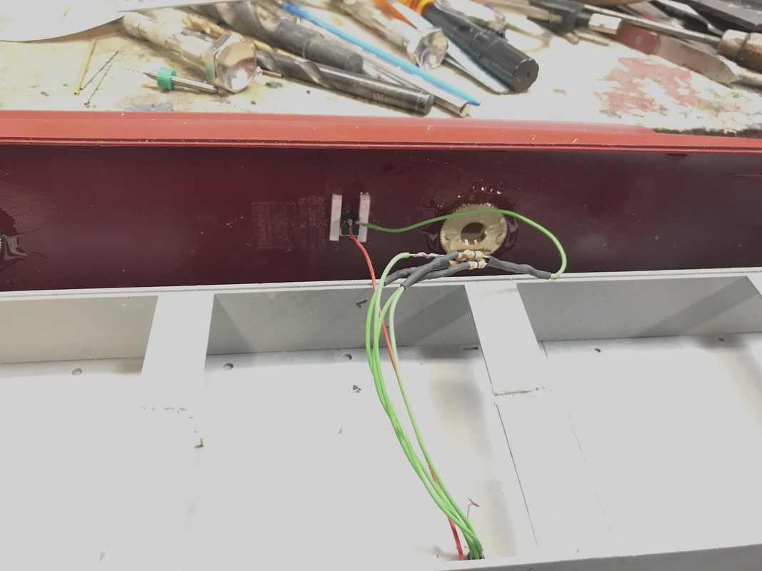
First thing I did today was elongate the holes in the hull to move the hull to starboard with enough clearance so the elevator safety nets will fit under the plexiglass cover. I held the pedestals over the holes and traced the perimeter so I’d know how much stock I could remove without exposing the hole. It gave me a good 3/16" which was all I needed. I then scribed the amount to remove and used a carbide router to clear it out. After again checking the clearance, I epoxied the brass thumb nuts into the hull. Again, I traced their outlines so I could correctly position them while curing. A little got into the threads on one of the nuts, but I got it out before it was fully cured. The nuts have a knurled edge with made it perfect for epoxying and will not spin or break loose. The thing in the middle is the connector for the 5VDC power source for the lighting.
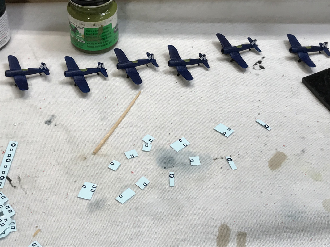
Then it was back to the little airplanes. I got the insignia on all the Hellcats and then did the Corsairs. As noted the stars and bars are separate decals and need to nestle together to look right. I began to cut them en masse so I could work a bit faster. I also was getting hang of handling little decals with a tweezers. I never thought you could handle little decals with tweezers. You can see how close I had to trim the star and one edge of the bars so they’ll nest together. BTW: the tail decals on the Corsairs are Trumpeter decals and went on well. Saved me design and printing time! The toothpick gives evidence of scale.
I always was under the impression that you had to “slide the decals off the backing paper onto the model” and with small decals that gets to be a miserable challenge. I saw a video where the guy was manipulating the small decals with tweezers. He’d pluck them off the backing and transfer them to the model. I tried it with these mini-decals and it worked very well indeed.
So I finished all the decals for all the new planes.
All that’s left is canopies and props. They’re not troubling and will be done tomorrow. The epoxy will be cured and I’m going to paint the lower hull with Tamiya hull red and then solder the lighting leads and attach the lower hull to the upper.
This is progressing nicely! I’ve never done a carrier. Seems like you’re build 1 big model and 50 little ones. Looking good.
This is coming along well, you have progressed a lot since I was last here.
Thanks Guys! Didn’t get much done this week due to family errands and buying a new refrigerator. The freezer was turing ice cream into…well…just cream. Small lead of Freon and it’s a 12 year-old unit so it was replacement time.
As promised here are the missing pictures from the last post. Post-Image started working correctly again.
This shows the little pieces of decals for the three-part stars and bars.
The epoxied knurled nuts for the pedestal hardware connection.
Today, I painted the hull Tamiya Dull Red… I wonder if that was a mistake since I’m sure that it should be “Hull Red”, but the label read “Dull Red”. I sprayed it in the garage with the door open since it started to rain. I actually got a couple of water drops on it and took it downstairs and force dried the first coat with the heat gun, and then sprayed another coat under cover. Wife had the Buick out of errands so there was plenty of room.
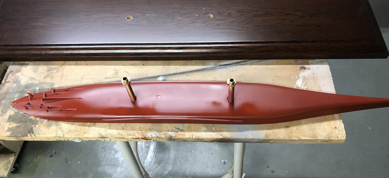
Paint was glossy as it was still wet.
Got back to finishing up the air wing. Found that Bondic was great for gluing on canopies. It’s the UV-curing adhesive/filler that’s sold in places like Amazon. It’s not cheap (about $20 for a kit with two tubes of adhesive and the UV-LED light source), but it worked great. Since it doesn’t cure until you hit it with UV, you don’t have to rush in getting things positioned or getting glue on unwanted places since it just wipes off. A small amount under the canopy, position the canopy and then shine the light on it for about 5 seconds and it’s solid. Since the canopies are transparent, the UV penetrates to the entire bit of adhesive and cures it all completely. I lost two canopies, one to the Rift out of a holding device and another got crushed. I was holding it in my small Xuron tweezer pliers a bit too hard to file the back edge of the canopy. Due to molding draft (the angle on molded parts that enables the part to be pulled from the mold), the canopies especially on the Hellcats was not nestling into the back of the opening. Well… I didn’t know my own strength and the part simply exploded.
So I was able to re-create the semblance of a canopy by using multiple layers of Bondic to build up the contour. I put on a layer, light it up, and then add another layer. It worked very well and after using the Sharpie to line it you can hardly tell which has a molded canopy and Bondic one.
Then a near catastrophe happened. I didn’t realize how precariously the hull was situatued sitting on my O’gauge railroad tracked shelf. I was trying to neatly position the entire air wing and the entire ship and all the planes headed for the concrete. I was able to break the fall of the hull so it landed with no damage (miracle) except for the elevator being bent upward in its mounting… very correctable. And of all the planes hitting the ground, four were damaged: one landing gear - reglued, one prop - reattached, and one prop lost to the Rift - modified. The only plane that is being scrapped is a Corsair that lost a tail and can’t be replaced. That tail was poorly mounted in the first place.
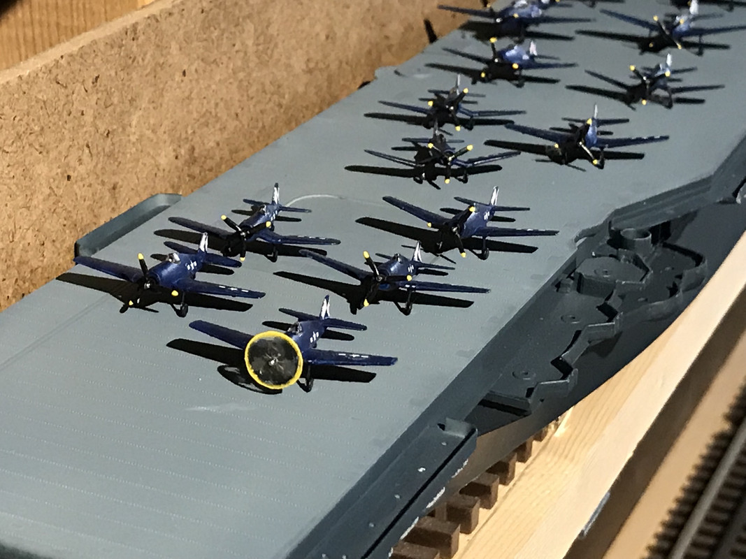
For the missing prop, I took it as an opportunity to attempt to make a spinning prop simulation. The prop radius meausred to 0.215". So I made a disc out of 0.010" clear styrene and glued a broken prop hub into it after drilling a 0.038". I then mounted this tiny hub into the Dremel and spun it slowly and painted the yellow rim. I then hand painted the prop sweeps using flat black. It’s not great, but it was worth the try. So the air wing is now complete. On this batch, I even went so far as to paint the oleo struts with the Molotow Chrome Pen. AMS rears its ugly head again!
Next session I will solder the lighting leads to the connector and then glue the lower hull to the upper and mount it to the base. Then it will be time to finish up detailing the catwalks and galleries, and mount many, many guns. I still have to rig the island before attaching it. It will be attached after I decal and weather the flight deck.
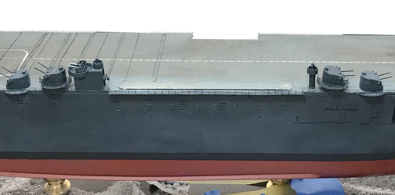
A rare weekend session and some progress to report. It was time to connect the hull to the bottom. I found that the width of the upper hull was wide than the lower hull and I was well beyond the stage where I could do filling. What needed to be done was remove the hull structural supports that Trumpeter molds in to strengthen the hull structure. When I cut, relieved and removed them I was able to pull the hulls sides in to match the lower hull’s shape.
I had to keep reminding myself to hook up the wires to the hangar deck lighting. Simple solder job. The center lead is the hot lead and even thought the connector in most electronics has three leads, only one outside lead is negative, the other is not connected. You have to do a continuity test to find out which one is real.
I was then ready to glue the two together. I used an old, short-bristle brush to smear on Testor’s tube cement. I didn’t want the glue to dry to quickly and any solvent cement would. I then fit the hull in place and used Tamiya masking tape to hold together any stubborn areas.
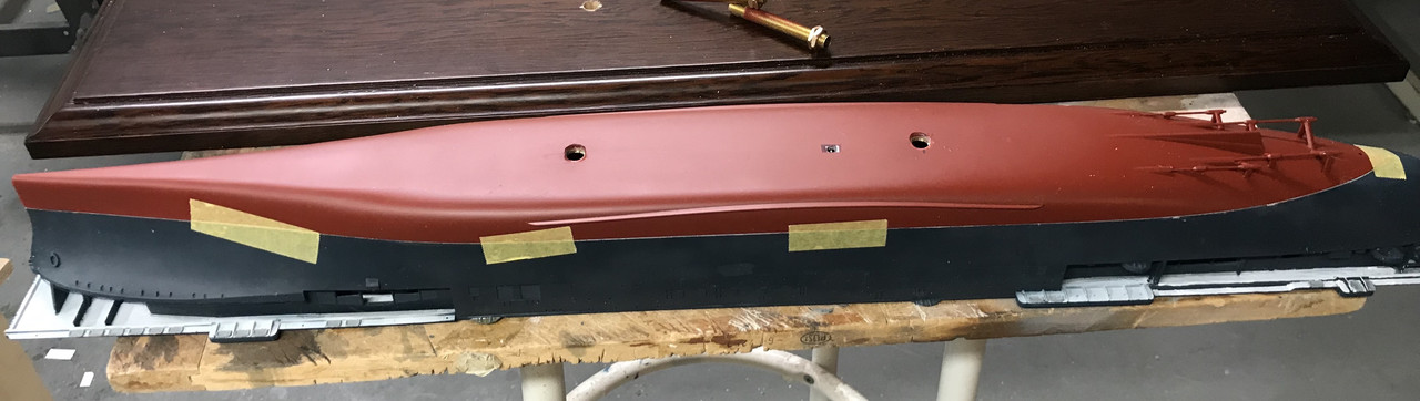
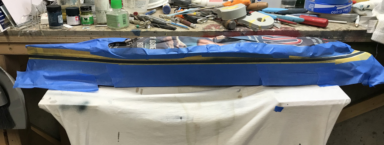
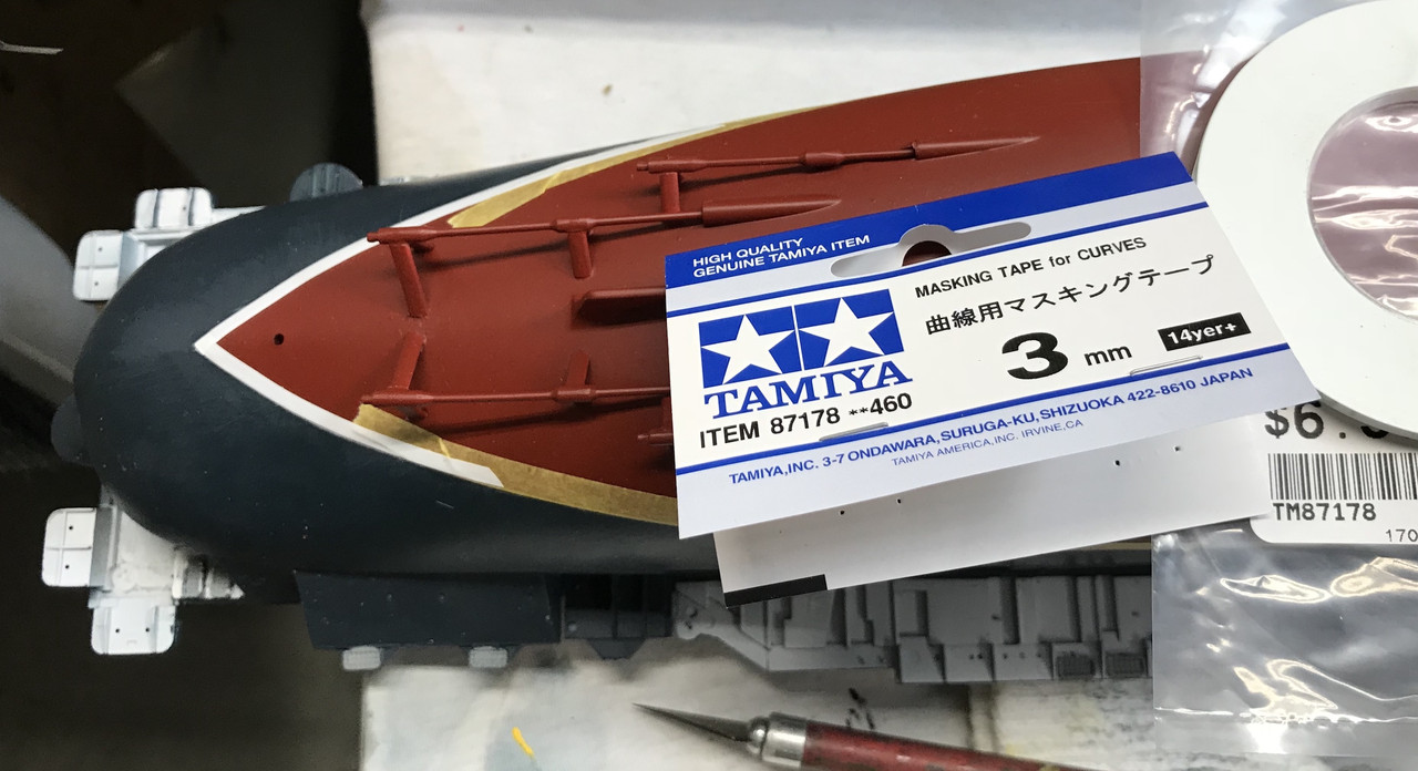
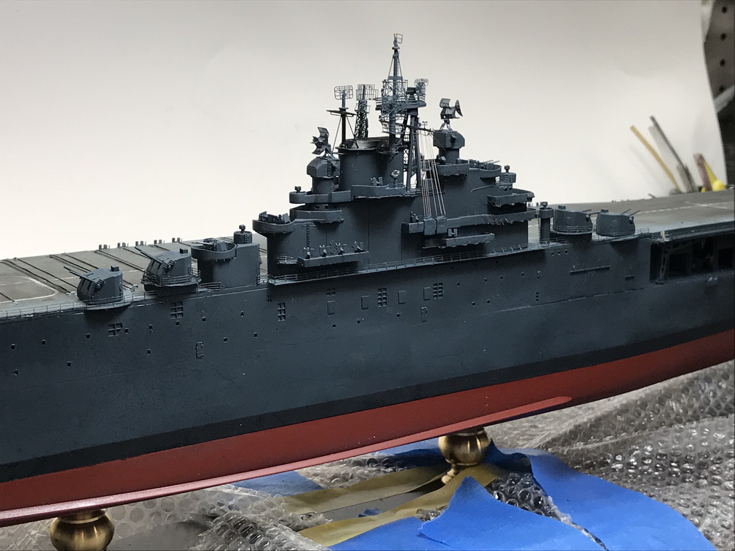
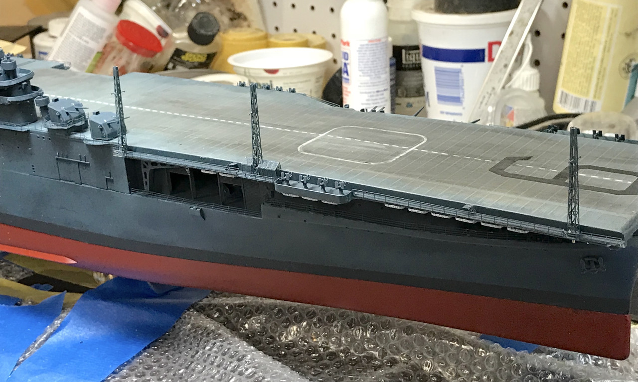
It was time to mask and paint the boot topping. I don’t know the exact measurement and, unlike Tamiya, Trumpeter doesn’t etch the positions of the waterline and boot topping, and I wasn’t able to run a surface gauge around to scribe an even line. So I did the next best thing and used Tamiya narrow masking tape as a guage strategically place pieces around the hull touching the existing waterline. I then used the same tape to create the line. This was all done after I masked the lower part of the line with thin tape and then thicker tape and finally newsprint with 3M blue tape. For the tight curves around the stern, I used a new product, Tamiya curve tape which is flexible and bends nicely around turns without buckling.
Boot topping was painted flat black. Once dry I permanently mounted the ship to the plank and then protected the exposed wood for the rest of the build with bubble wrap. I found some damage to the elevator due to the ship’s fall to the concrete last week. I will repair the elevator as best I can… the PE looks pretty pathetic…and I’m going to install it in the lowest position which I couldn’t do before. Making lemonade.
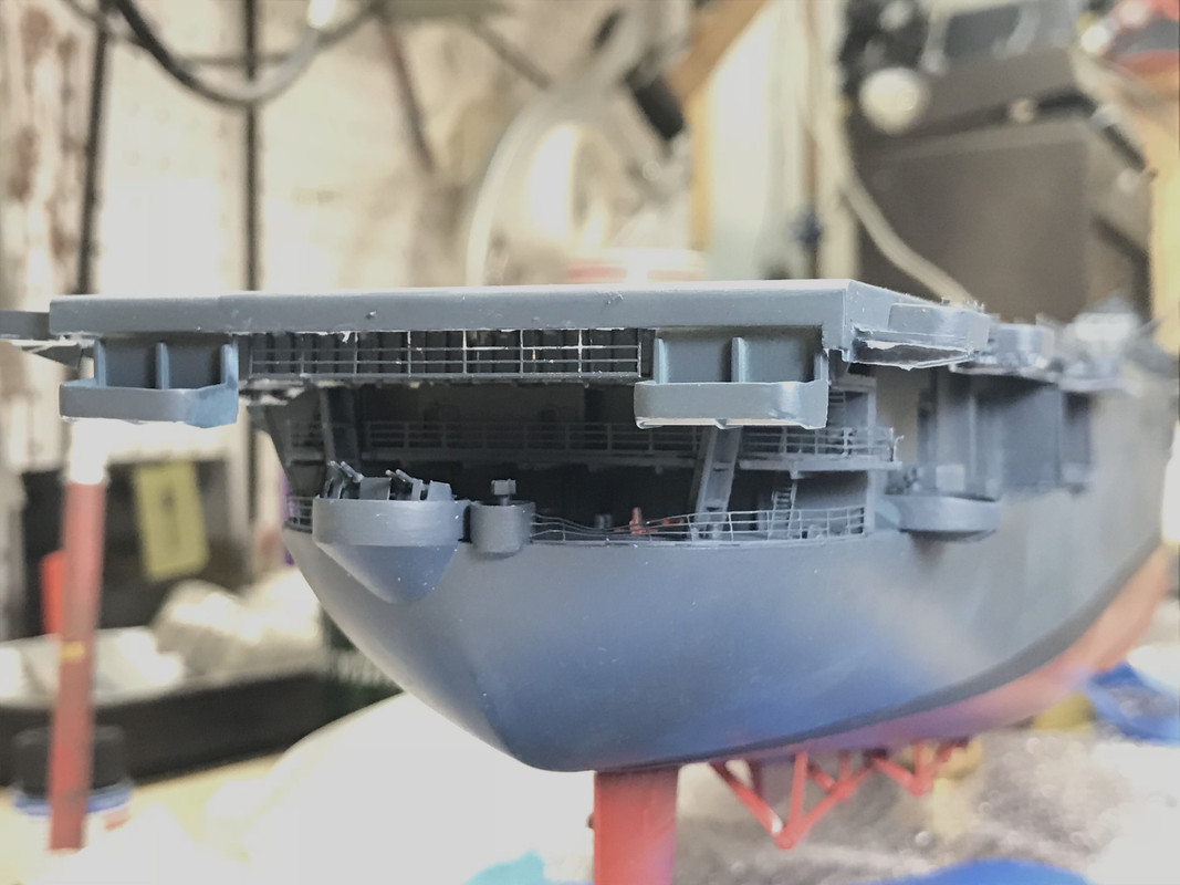
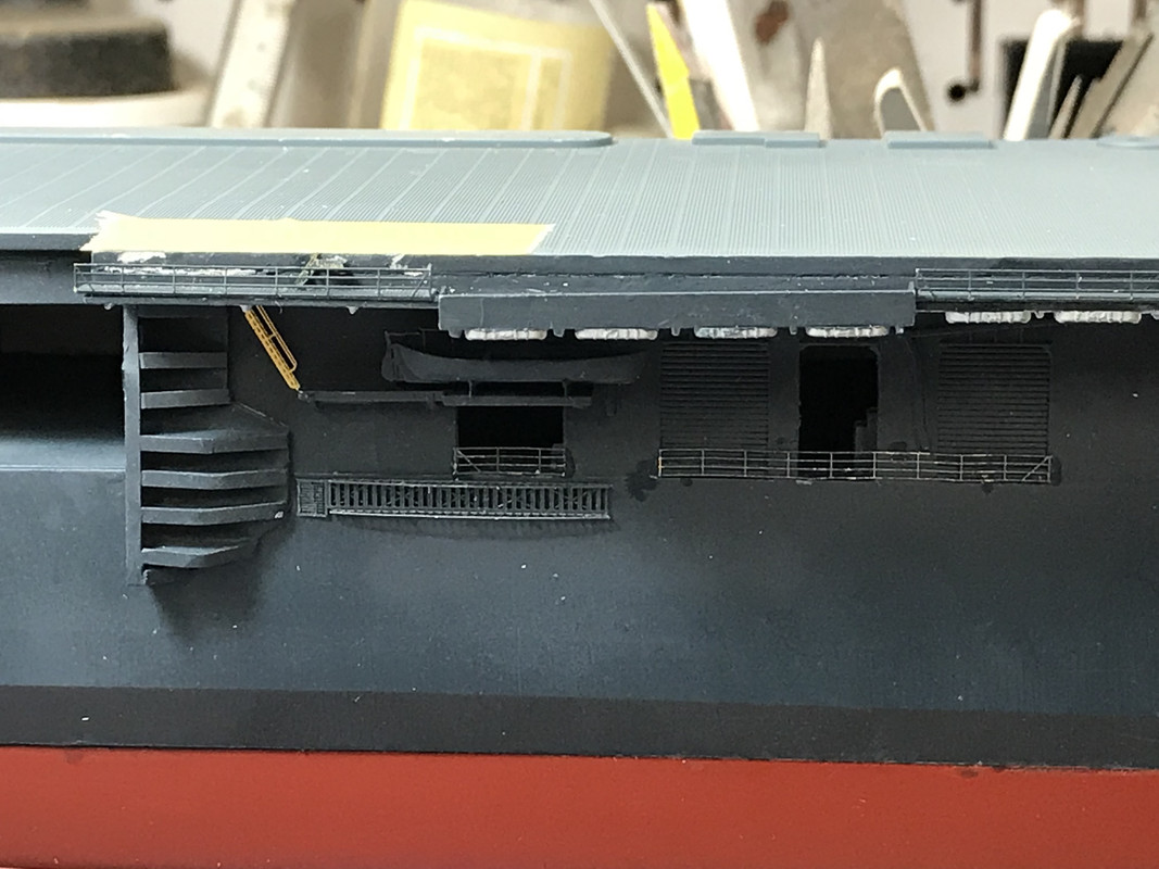
With the model mounted and base protected, I turned the whole deal upside down and rested it on the flight deck and finished installing the hanging catwalks under the bow. There are four of them. Two which I has installed before and that fell off, and two more just under the flight deck’s forward edge.
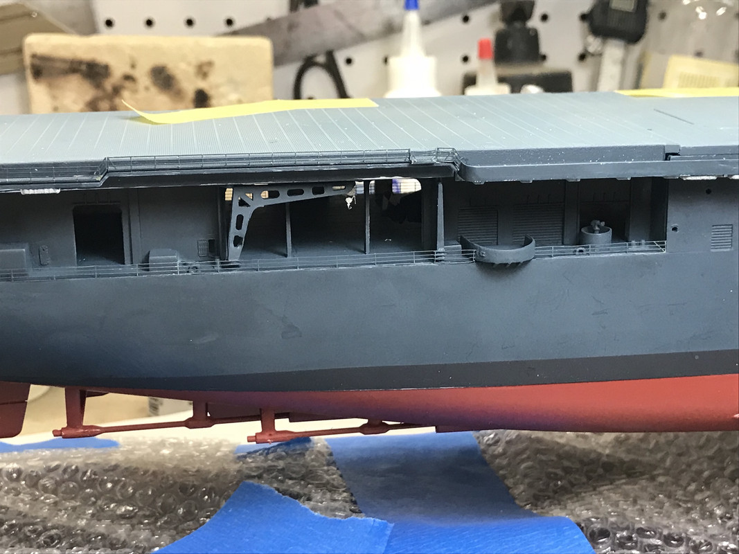
I turned it back rightside up and started installing the catwalk railings. GMM includes a lot of standard railings to be glued to the plastic catwalks on the model. On the upgrade set, GMM has a catwalk that has 3 folds, a under-bracing, the perforated catwalk and the railing. You’re supposed to cut all the kit catwalks off (which I hadn’t done) and then edge glue the folded assembly to the existing spot. I was not happy about that so I chose to glue the perforated assembly directly onto the plastic catwalk. It’s the best of both worlds since you can see the perforations when you look down on them, but they’re much more secure.
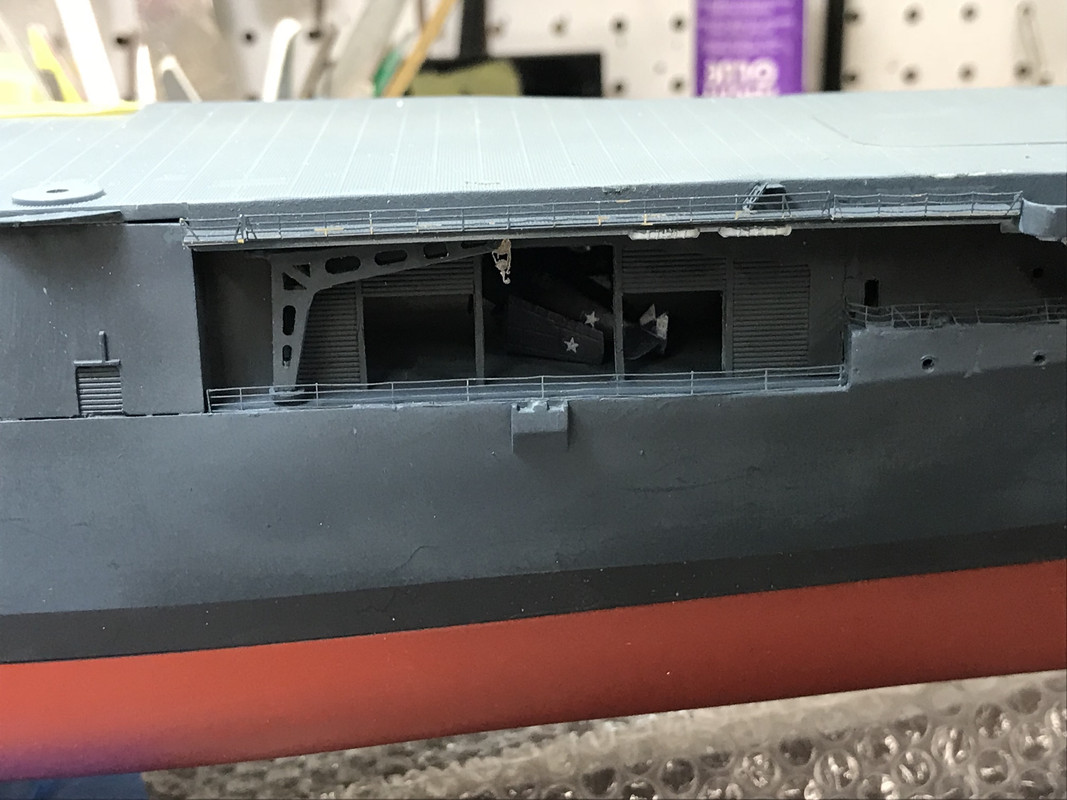
Then I noticed something on the floor. It was one of the twin 20 mm gun tubs AND it was flattened by my desk chair wheel. It wasn’t a lost cause, just a hospital case. I removed the crushed plastic splinter shields and the under-bracing and sanded the surfaces smooth. I then fabricated new shields and bracing using the same Evergreen strip that I used for the scratch-built railing on the island.
The end result was glued back in its place. No harm, no foul. The thinner shields look better, but it does make the tub a tad wider since I’m gluing the shields onto the perimeter edge and the kit’s come straight up from the end.
The reason I was able to work on a Sunday was my number 2 grandson had another school project. He’s in 8th grade and finals are next week. This time was project was creating a mouseleum and crypt to be used in a Romeo and Juliette discussion. He did most of the work and when I wasn’t helping him I was building an aircraft carrier.
This was my first Trumpeter big ship kit and, while I understand the reason for the two-part hulls, I find the results to be sub-par. It’s a very long glue joint that is very easy to have mis-fits. I can imagine that it does make building a waterline model easier, but it makes doing a standard build harder than it needs to be.
First, I thought I took a picture yesterday of the Tamiya curvy tape, and I had, but it was in my deleted photos on the iPhone, so I retrieved it and here it is. You can see how nicely it conforms to the curve.
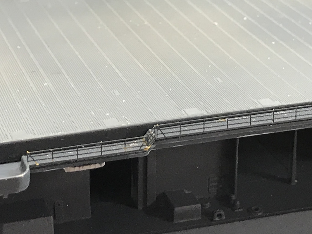
Today, I turned the ship around and put in the catwalk rails. There were some wrinkles to this side since the rails go up and down around the places where the long range radio antenna go. You can just do a straight bend on these rails since it will impinge on the parts that bend at a different location, so some of the smaller bends were done the old-school way, pliers. There are simulated steps included in this piece of brass that gets folded at an angle to conform to the plastic and the railing.
Before the brass can go in place, I had to mill off plastic bumps that were used to locate the kit’s antenna bases. It looks like heck, but it gets covered by the brass and touch-up painted. This is creative destruction. When modifying models you always go through this “demo” stage before it gets better.
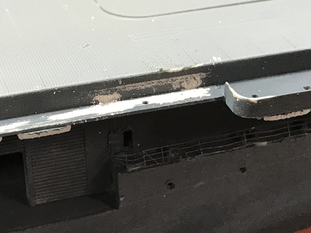
In this pic there are two brass folded parts; one on the upper and one on the lower levels. The stair component is part of the upper brass piece. Really spiffs up the edges of the flight deck.
There are a passel of small ladders that go from the flight deck down to the catwalks. These are part of the basic GMM set. GMM doesn’t specifiy where they’re supposed to go and says, “check you reference material”. I don’t think they going into the gun tubs since there’s no room. Besides, the model doesn’t include ready-ammo lockers that would be near the 20mms I presume.
The above shows the catwalks after the first round of touch up painting. After I put these small ladders in place, I’ll go back and do it again. I definitely can appreciate the delicacy of removing the plastic catwalks before attaching the brass ones, but I assure you, they would have been very, very fragile and prone for detachment if you happen to hold the model the wrong way.
I also added the stern catwalk that sits between the aft 20mm gun tubs. There was a diagonal brace that was supposed to be added to this facing rearward, but after fussing with it and not being very happy, I scrapped it. And after looking at this picture I noticed that crushed railing which I’ll have to straighten. It’s exactly what I noted above about PE railings being prone to getting zapped. The catwalk needs touch up painting that will happen tomorrow. I like how busy that fantail is looking.
I have some more railings to go on the hangar deck level, the ships cranes and the radio masts. Since the radio masts are not going onto brass, not plastic, I’m thinking that I may attempt to solder them with TIX solder which melts below 300 degrees. Otherwise, It will have to be epoxy. I may also try soldering a flat piece to the bottom of the antenna tower with a drilled hole and soldered pin, and drill the catwalk and pin it. I’ll noodle in my brain awhile and see which method wins. I test fit the island and it needs some relieving to fit nicely over raised deck lugs. I don’t want to force it and develop any undue stresses in this very complicated assembly.
Installed all the railings bordering the hangar deck today plus got some more stuff in place including the rest of the those finicky little flight deck/catwalk steps. You can’t imagine how much trouble some of the smallest details can cause you…
I should have put the cranes in BEFORE the railings since I almost thought I couldn’t get them in without doing damage. As it was, with some delicate coaxing, I was able to get their pins into the holes and installed. The railings spaces were measured using a paint of dividers and I took some liberties, especially on the port side, where I ran the rails across some bulkheads instead of individually cutting and gluing. I did this mainly because the sizes were not neat multiples of rail stanchions and would have had a lot of little tiny railing ends causing me problems.
After installing the lower rails on the starboard side, I used the fine-line airbrush to retouch all the Navy and Deck Blue and get the brass blended with the rest of the model.
This is the aft crane.
And here is the fore crane.
There was a cross hangar deck catapult on the as-built Essex. It was removed when they added (as I did) the two additional 40mm mounts. I’m not sure if the starboard catapult was still in place. I have that part, which is stowed vertically, to put on if it is correct to do so.
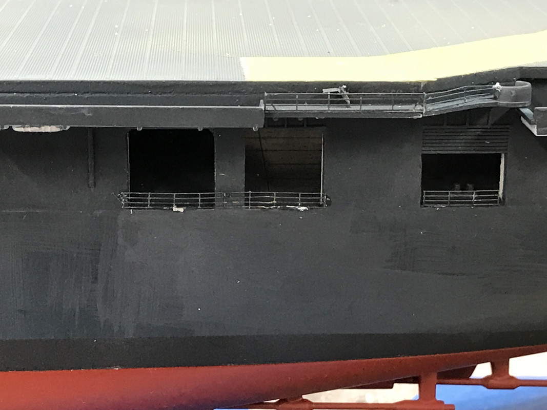
The port side has all those rails that cross between roller doors. I know what I did is not ptototypical, but it was expedient.
The foremost roller doors don’t get railings since the sponson now has a splinter shield surrounding it. It did get just one little rail on it aft-most door. And then I added a railing around the gun director platform next to it. Incidentally, there are rails around the five inch mounts, but a) they weren’t called out in GMM’s instructions, and more importantly, b) I would have soldered them to the circular platform since CA’ing it seems like a exercise in futility. So I probably won’t attempt to add them.
Here are the other areas that got these railings. Note, the port side has NOT been touch-up painted. That will come tomorrow, and I’ve already masked parts of the flight deck so the overspray doesn’t ruin that lighter blue flight deck.
Notice the nice shiny new inclined ladder. There were two put on this side. Speaking of vertical ladders… I almost lost an entire fret of them. I had purchased an extra set of inclined ladders since I had ruined a lot of those included in the GMM set. This next bit is going to be a bit hard to visualize, but bear with me. My workbench is heavy plywood covered with Homosote (a press paper-board building panel). I used Homosote since it accepts T-pins very well and makes a great building surface for things that need to be pinned… flying RC models for example. There’s a 3/4" ply wall at the work bench end and there’s a tiny gap between the Homosote and the ply. This fret slipped down about a 1/4" and it was so firmly fixed in that groove that I literally had to take cutters and cut the fret away (after destroying half of the inclined ladders attached to it). The lower part is still in that groove. All I can imagine is somehow CA got in there and glued it in. I put a huge amount of effort in attempting to pull it out and it didn’t budge. So I was able to salvage enough ladders to put the two on this ship. There’s probably a few more that will work on a future project, but the rest are ruined. Murphy strikes again!
The companion ladder is stowed where it is supposed to go. And I see another spot that needs a railing… leading to that boat deck.
Tomorrow, I’ll start putting in some guns (I think). I need to paint the prop shafts (anti-fouling white), and prepare the plastic props. I was thinking about buying G-Force brass props like I did for the Missouri. They look pretty good. I may still do that for this ship.
I will get the anchors in place, start preparing the flight deck for decals and weathering, and then start rigging the island. There are tons of antenna and flag halyards hanging on that part. I also have to install and rig those long-range radio antenna. What’s the best way to fasten the aircraft to the flight deck?
Actually, ESSEX CV-9, was commissioned with no catapults at all. The athwartship cat at the hangar deck level was never installed. The track for the starboard flight deck cat was installed, but there were no cats available. The catapult itself was installed 6 May 1943 and was a spare H II cat, designed for the Yorktown class. There were 2 H IV cats at Puget Sound designated for ESSEX in late 1944, when she still carried the single H II. EJ
Thanks! That’s really good to know.
Today was part success and part struggle. I decided that before I attached anything that goings to stick out I better do all the flight deck treatments so I don’t break anything. I did install two 40mm sets in the starboard aft tubs which is when I came to the conclusion that any more guns would be zapped, so I stopped.
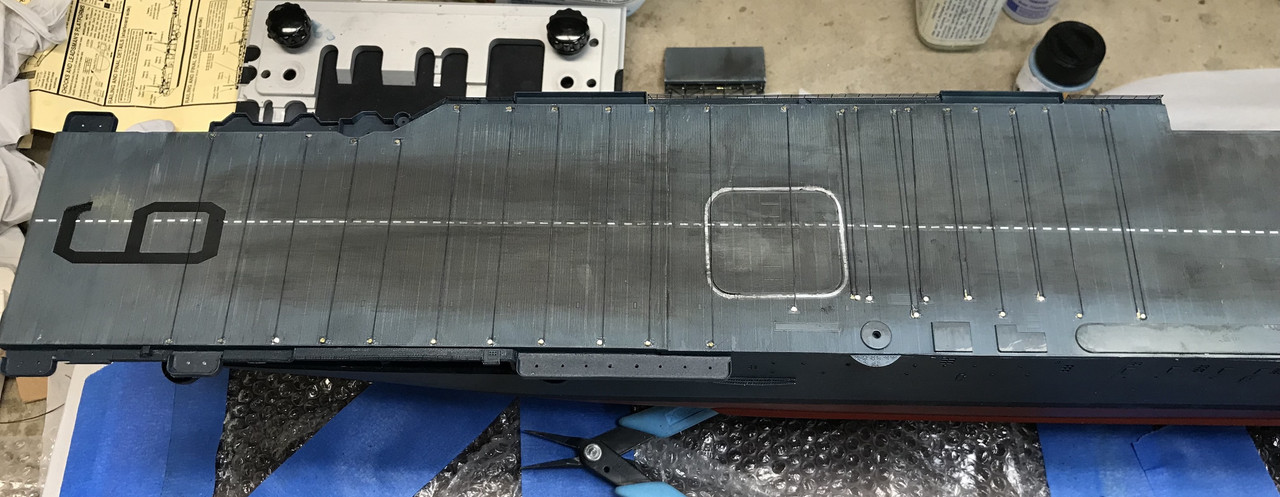
I wet-sanded the FD to expose the wood tones below and this effect looked pretty good.
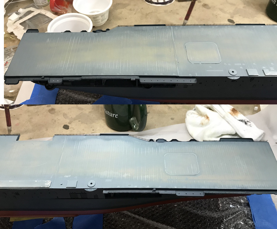
After sanding I tried (for the first time) to use Vallejo dark gray wash. I works, but it did darken the entire deck, not just in the crevices which is what I really wanted to do. So the flightdeck looks like it was painted with standard deck blue instead of the lighter deck blue flight deck stain. I’m sure those wooden flight decks took a tremendous beating and had all sorts of colors working between wear and tear, tire marks, fuel and oil spills, sea water, rain and sun exposure.
I then sprayed some Tamiya gloss clear to get ready for decaling. My first indication when I was putting on the first #9 on the fore flight deck was when the decal started falling apart. I hate when this happens. It was an old kit (copyright 2002) and the decal showed it. I pieced together the broken bits as best I could and then got the MicroScale Decal Film solution to create an new film on top of the old decal. The second #9 performed better, but it was touch and go.
To lay down the single center line dotted line decal I laid down some Tamiya tape to establish a datum and then laid the decals near it. The stripe decals came in many segments. I found a couple of them broke, but it was minor and didn’t cause a problem. I then noticed that the 9s go on top of the stripe so I had to piece the stripe to get the same effect.
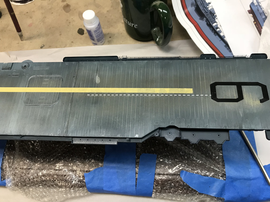
Then came the white stripe decals that surround the mid-deck elevator openings. These turned out to be a total nightmare. I should have put on another coat of decal film since one coat worked momentarily and then they started falling apart.
For the broken parts of the fore #9, I hand touched it up with flat black and it will look okay after dull-coating, but these elevator stripes will not work with my hand painting. So I’m going to make the corrections in the computer and then make some white decal striping and see if it works. I really can’t blame Trumpeter, although I’m generally not impressed with their decals. The best advice I can give is don’t panic. Take as much care as you can, and if you suspect the decals are old, overcoat them immediately. And use two coats.
So here’s what it looks like so far. I then have to dull-coat the decals after the fix and start doing some tire marks/rubber scuffing stuff.
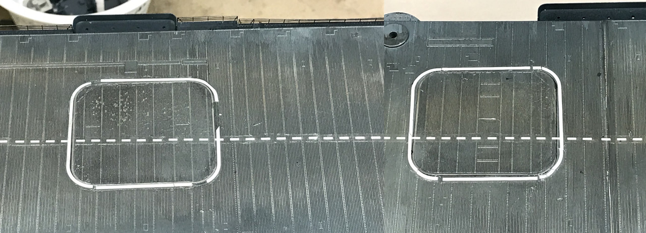
I’m pleased with how the strip down the middle came out, and bummed by the elevator decals… so I’m batting 500. I took a top-down picture of the striping and measured the particulars with the caliper so I have what I need to make the correction decals.
I also touch-up painted both sides with the detail airbrush. I like that tool even though it’s definitely not up to Badger quality, but the price was ridiculously low. It’s great for small delicate jobs.
Today’s post is a two-fer since I didn’t post yesterday, but did some work. First thing I did was test out an idea: a way to simulate polished brass (bronze) without spending $$$ on real brass and not being satisfied with any brass-colored paint since they’re particle based and do not reflect light as a polished metal surface would. I first coated a piece of plastic with my Molotow Chrome Pen which does lay down a really reflective surface. When it was dry I brush-painted Tamiya Clear Yellow in two coats. The result, while be a bit rough due to my not-so-careful use of the chrome pen, was encouraging.
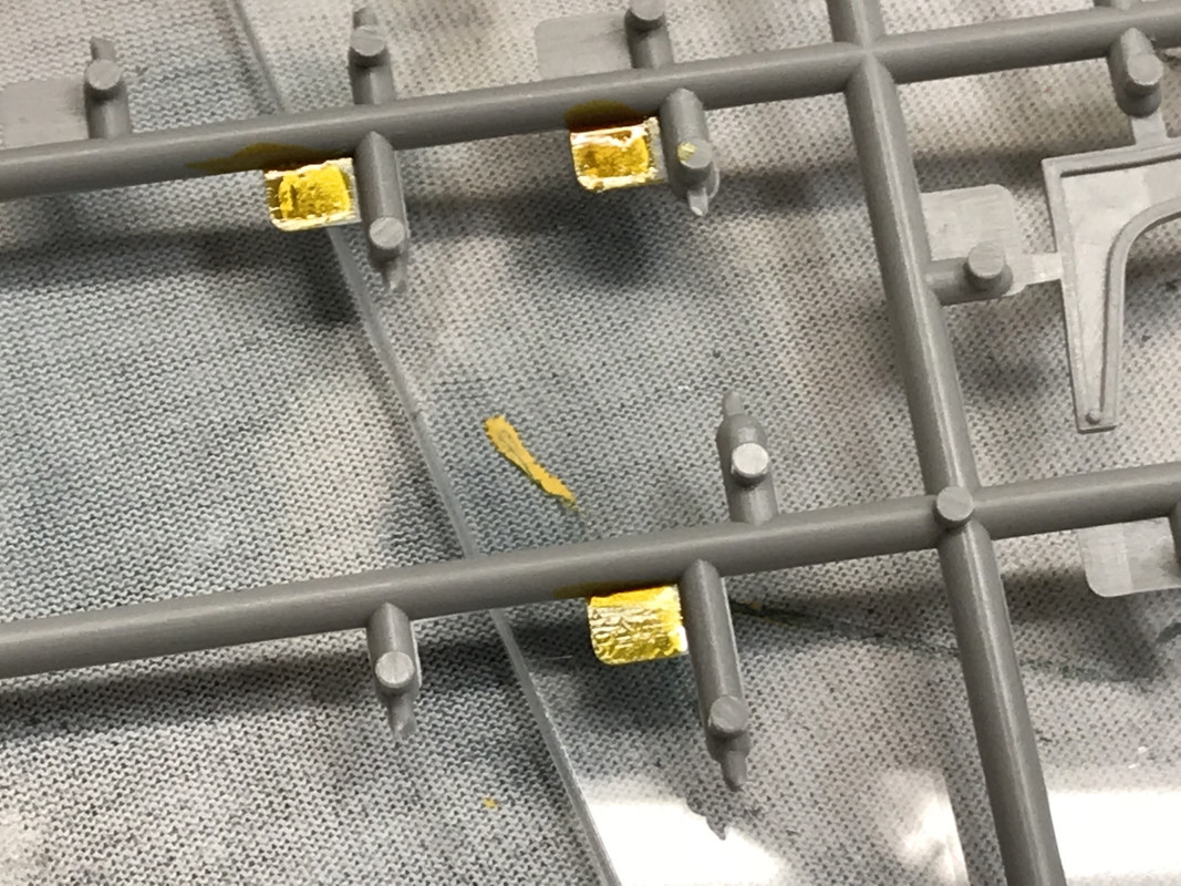
I then coated the propellors while on the sprue (for convenience) with the chrome pen and let it dry overnight. I made the mistake on my test piece to touch the chrome thinking it dries really fast and messing it up. It does dry fast, but I was laying it on pretty thick.
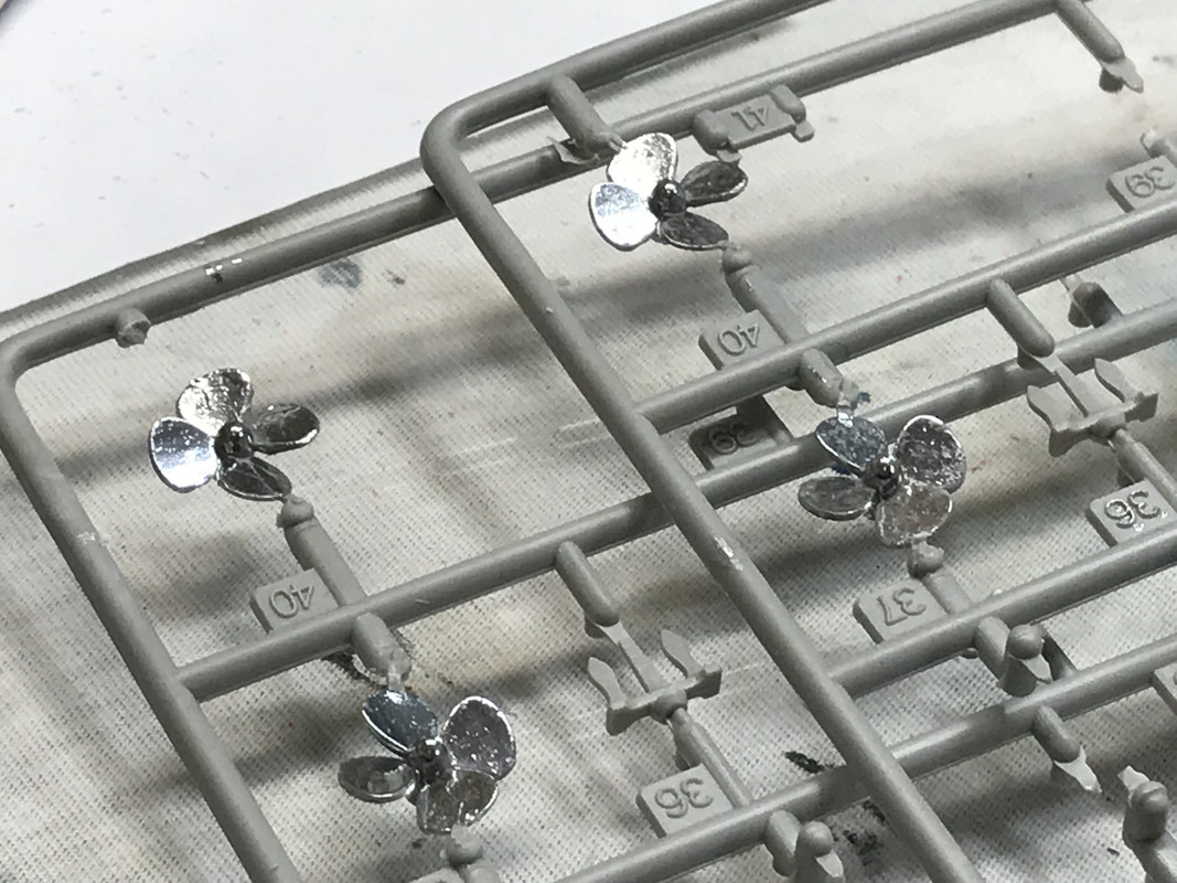
It’s a very convincing metallic surface, unlike any model paint I’ve ever seen.
Today I airbrushed two-coats of the same Tamiya Clear Yellow and am letting it dry overnight also. If I need to shoot it again, I’ll do it the next session.
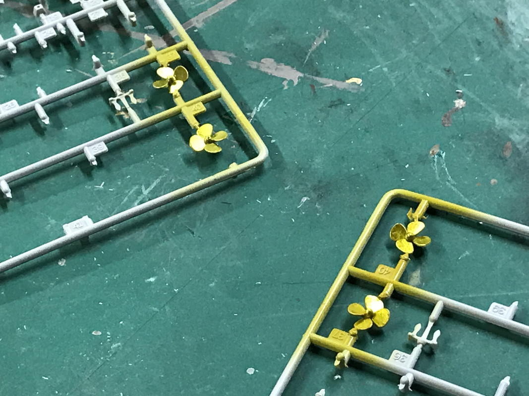
It’s pretty convincing and I would consider the experiment a success. Next to buying G-force props, this would be a good way to go.
I spent a lot of time hand-painting the touch up of the broken elevator edge decals. I was trying to make my own white striping decals on CorelDraw, but it crashed my Windows environment on my apple and it was taking a long time to reboot so I chose to attempt the hand painting approach. I started weathering the flight deck. I did so with black weathering powder put on with a short bristled brush in directions that tire wear and skid marks would go. The white striping isn’t great, but it will work.
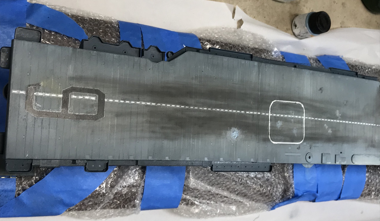
I finished the powder weathering and had the screwy idea of putting some fuel/oil stains. I overdid it, and realized that oil on the deck would be cleaned up very quickly to prevent slips and falls. My reason for doing this was the light spot on the after deck that I wanted to hide somehow.
I showed my wife this picture and she agreed that the spills were overdone. The oil stains were done with Tamiya Clear Smoke and is alcohol soluble, so I used a clean brush with isopropyl 91% and blended the stains back into the general grime of the flight deck. The flight deck grime now extends over the elevator lines further making them less pristine and noticeable to the viewer.
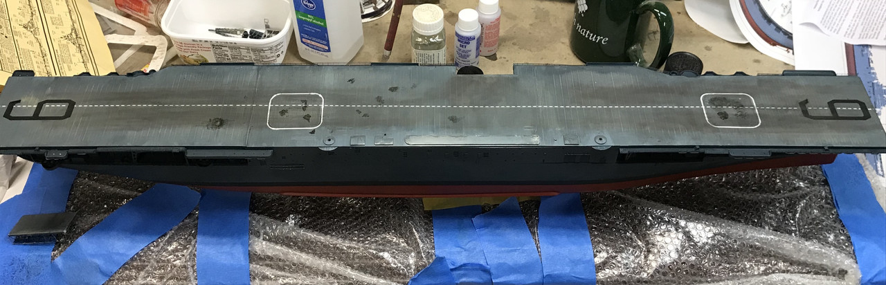
After this work I want to install the arresting wires. The ends are very small, folded PE to simulate the above-deck pulley system. The wires themselves are E-Z Line heavy gauge Lycra elastomer. Since these lines are actual a series of very fine fibers and as such, instantly absorb CA, and because of it’s huge surface area, sets it immediately (whether it’s thin or thick CA). I wrapped the line around the far brass cap before folding it down, added thin CA to secure the line and then folded the cap down onto the still-totally-unset CA. After all were installed I hand-painted them deck blue. When Essex was first launched it had arresting wires on both ends and GMM includes enough PE to do this, but later in the war, they realized that landing from the bow was a bad idea and all those systems were removed. The units with the double lines are the pop-up barriers that were there to catch planes that missed the wire. They didn’t have a bolter capacity since it was a straight deck carrier and the bow was not often clear for the plane to go through. It was why the angle deck was developed by the British to enable capturing AND launching at the same time and giving the aircraft a clear go-around path.
I think the wear and tear on the FD is okay, but I’m not weathering the rest of the ship. I’m wondering how soon after shopping would the flight deck show this amount of use without the rest of the ship following suit.
Next up was the Long Range Radio towers. The initial scheme I came up with was too fill the tower base with Milliput, 2-part epoxy putty. I filled the bottoms yesterday and let it cure overnight.
Today, I drilled the putty for a 0.032" brass pin and drilled the catwalk for same. Unfortunately, two bad things happened. First, the putty did not cure as hard as I would have hoped. The brass pin didn’t secure well in it with CA. Second, when attempting to push the tower-with-pin into the hole in the catwalk I had grabbed it too firmly and deformed the heck out of the very fragile PE tower. After much messing with it, I got it reasonably symetrical, then proceeded to crush it at least three more times messing with that pin. I finally succumbed and put the pin in the catwalk, not the tower.
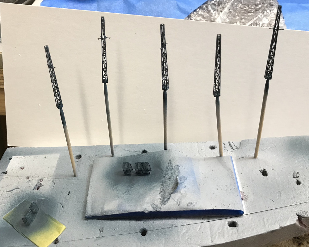
The brass pin did one more thing, it kept pushing the putty further up in the tower, negating it’s value. I then did what I should have done in the first place; use Bondic UV curing filler to make the bottom plug. I did this and created a much stronger, harder base to drill for the pin. Armed with this knowledge I got the other three towers into place. They’re not glued in yet, but I did paint them in place using a piece of cardboard to shield the rest of the deck from the Navy Blue airbrush.
I accept all feedback and criticism, but I frankly think that the grime over the white elevator striping seems to make it much more real. If you agree or disagree please let me know.
For some reason, FSM’s website was unreachable yesterday, while all the other Kalmbach sites were active so I suppose they were doing some maintenance. So today’s post is a 2-fer.
Loren Perry at Gold Medal Models has come through again and is sending me replacement PE for the price of postage. I’m replacing all of the Long Range Radio antenna towers and the framing under the exterior elevator. He also said I’m going to get a lot more. I could also use the cage that surrounds the down leads on two of the LRR antennas. Hopefully that will be in this bunch. The under framing on the elevator is just a mess and really needs to be ripped out and replaced. With scratch-building you have the control to remake a poor job, but with commercial parts when you screw up, you’ve screwed up.
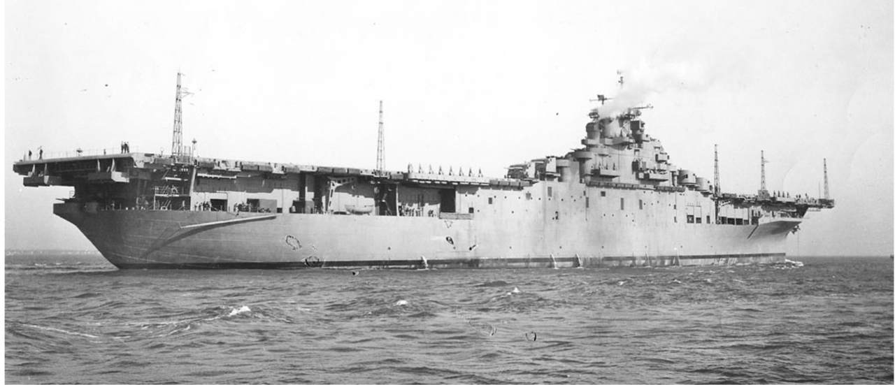
While I’m waiting for the PE to arrive (Left West Coast yesterday), I decided to add some railings that aren’t in the kit instructions or GMM’s. I’ve seen evidence of railings around the circular platforms for the elevated 5" twin mounts, along the flight deck outside of this gun area, AND a catwalk that runs parallel to the outside of the island’s starboard side. There is no provision for this catwalk either in the kit or GMM’s set. This was on a drawing of the Essex on NavSource and found clearly in this picture and it’s a mounting place for nine floater net baskets.
For the guns I formed some railing and wrestled it into place. The first one went very smoothly and lulled me into a slightly euphoric state that was quickly dispelled when I did the second. This one did not go nearly as easily and with persistence got it done.
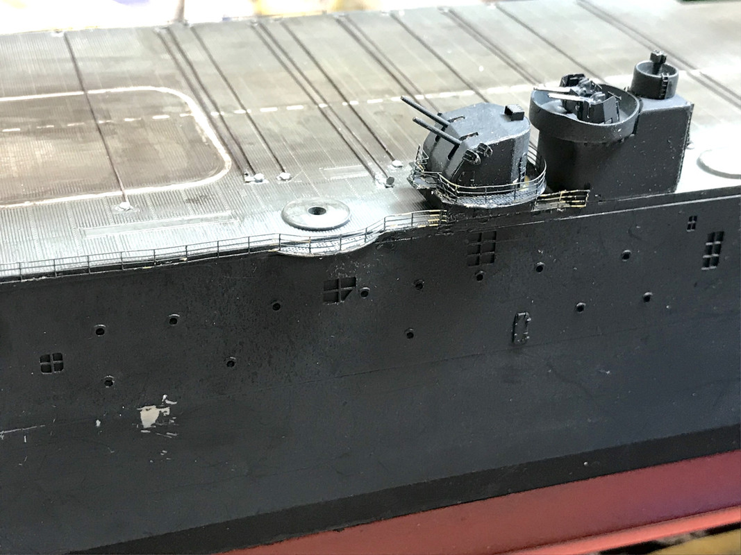
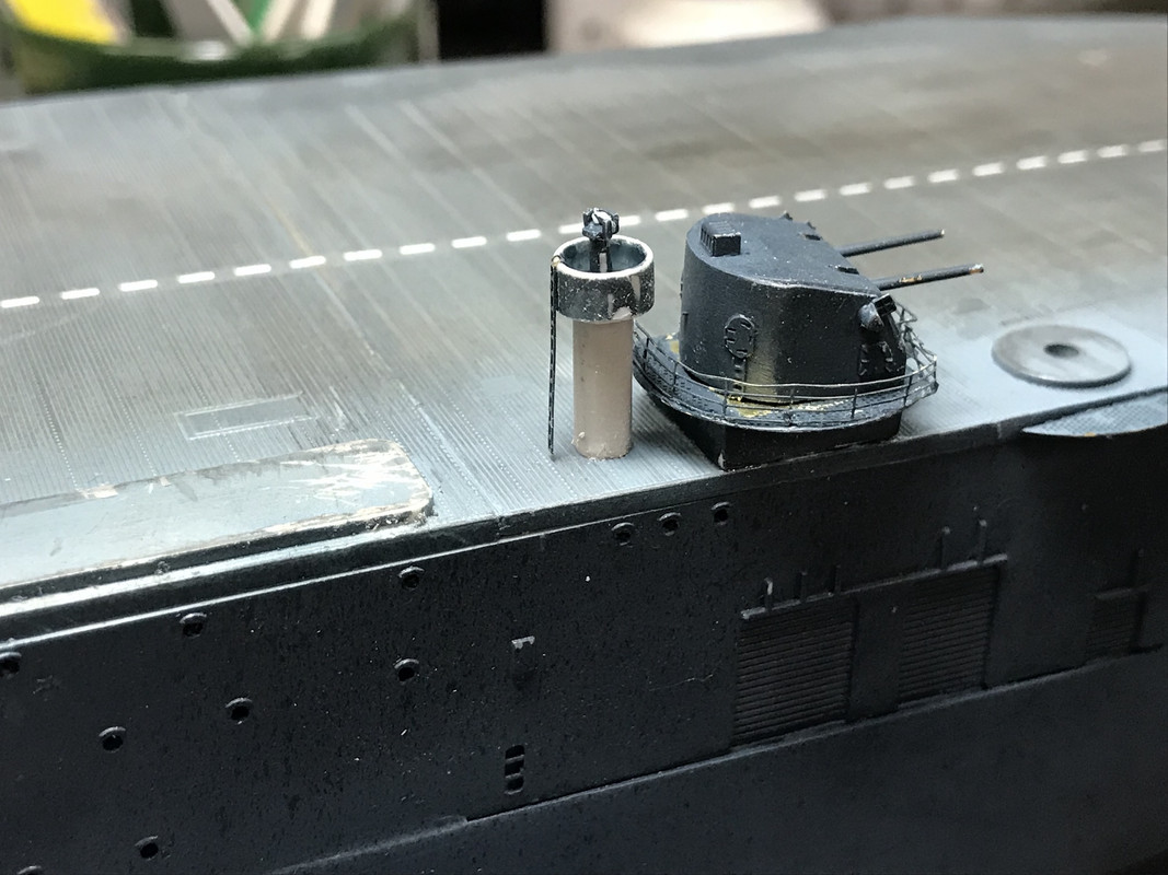
There is also a railing along the flight deck that runs around the circular platform up to the elevated mount. While this looked daunting, it really wasn’t so bad. There’s another small snippet of a rail between the elevated mount and the 40mm elevated mount and then you come up to the area of the catwalk. In the below I’ve put the last Mark 57 director tower in place with a PE access ladder. All today’s work needs painting/re-painting. This foredeck area will also get the railing that will go around the circular platform, but it’s a bit shorter (i.e. easier).
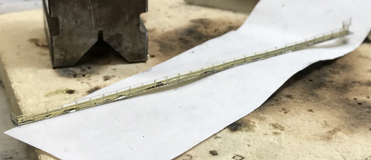
To fabricate new island catwalk, I cut off a piece of PE fret which is same width as the kit’s catwalks (lucky!) and soldered some straight rail onto it. I’m also going to add some brass attachment pins on the bottom so it will be easier and more secure to mount. BTW: PE fret brass is very convenient for scratch-building all kinds of small parts that you wish to solder together.
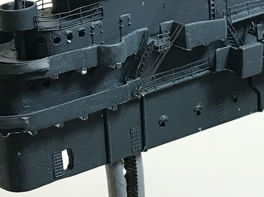
The last thing done yesterday was repositioning the companion ladder. It probably needs some rigging on the outboard end that will “support” it. You can see the damage from removal that will be touch-up painted. There’s a small added 90 degree rail at the top of the ladder that was needed since it was open to the sea. Now this is really funny… I found that broadside of the Essex (above) AFTER I changed the ladder’s positoin from lying flat against the hull to a more stair-like position. But guess what… if you look closely you can see this ladder flat against the hull as I had it glued in the first place. I now have it in the deployed position. But this means I’ll need to rig it so it has some form of suspension since it’s now hanging out in space. GMM’s instructions simply said glue in front of or behind a specific place on the hull, but didn’t really define its orientation.
With the new PE coming I won’t have to settle on some very sub-par work that would have detracted from the overall beauty of a model of this caliber. As the late great Gary Kohs (founder of Fine Art Models) said, “A fine scale model has detail that draws you into it where you discover ever more complex things to see.” My Missouri model is like that where you get an overall view of its complexity, but as you look closer you see things like the foot rest under the flag bags, a detail that’s almost invisible unless you really drill down with you focus. This ship, I hope, will have the same result.
Now onto today’s efforts. I finished adding the front railing around the foreward gun mounts. I then soldered (using TIX lo-temp solder) some Phosphor-bronze 0.020" wire pins to secure the fabricated catwalk to securely to the hull. I used the resistance soldering tweezers to solder the pins so they would be held in place while the solder cooled. The lo-temp solder melts before the normal solder holding the railing would so everything was in control. Before putting it on the ship, I painted it with a coat of Tamiya gray primer. I located the three mounting pins on the side of the flight deck edge very close to the top so the mounted catwalk would be level with the flight deck and drilled the three holes with an 0.021" carbide mini-drill. I added thin CA AFTER putting the catwalk in place to make it permanent.
I hand painted all the newly added railings and gun director tower since I didn’t want to have to mask the whole flight deck area. I also touched up the marred area on the hull from the ladder removal.
It was time to put the props on…
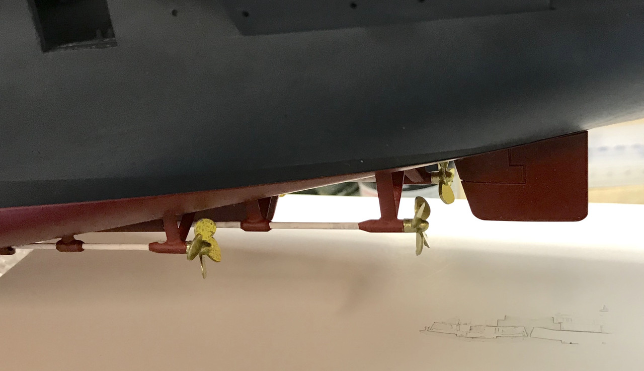
Hard to tell they’re not really brass…
I started adding all the remaining guns and whatever directors were still needed to be added. Two more Twin 40s, and the four single 5" mounts go onto the port side.
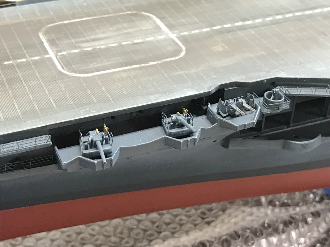
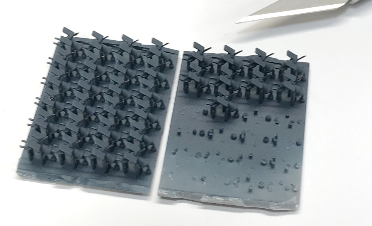
Lastly, I started adding the remaining 40, 20mm gun mounts. I don’t have enough of these (DOH!) and ordered one more set of 24 from Freetime Hobbies. These Blue Ridge 3D produced tiny models are exceptionally fine and look very, very good. Plus you don’t have glue microscopic PE shields, shoulder supports or handwheels onto very small plastic things.
Before gluing them in place I needed to paint them. On the island I painted everything with an air brush, but now all the gun tubs are already painted. So I air brushed the entire rack of guns before removing them from their mounting block. This included picking out the barrels with Tamiya gunmental.
I got five guns in place before quitting for the day. They look really spiffy! (IMHO).
Tomorrow, I add as many guns as I have and then start working on island rigging. Getting close folks. I’m expecting the plexiglass to be ready any day now and I have to put that together. I also need to have a brass plaque engraved (like I did for the Missouri) to tell something about the model with as much of a quality look as the base, case and model demand.
I put the remaining 20mms that I had in their various tubs and need 16 more which have been ordered from Free-Time Hobbies. I then finally bit the bullet and started rigging the island. When I did the island mods, the inner width got a bit narrower and was not slipping over the boss on the flight deck. I really couldn’t force it for obvious easons, so I carefully scraped a chamfer on the inner edge to make it a bit wider and able to fit better when it will be glued. That will happen after rigging.
I cleared the workbench for action and held the island in a hemostat which in turn is held in a drill press vise. I started on the port side for no reason other than it was the one that was facing me. The first lines (E-Z Line fine-gauge black) are three radio antennas that belay onto the side of the fore island. I did the same thing here as in the Missouri; inserting some piano wire pins into drilled holes to wrap the E-Z Line around. When I say pins I mean pieces of high-E guitar string which is 0.010" in diameter. The drill is ridiculously small and fragile. I constantly break them just by laying down on the workbench improperly. This image is hugely enlarged since those pins look like big steel rods. Actually the pieces are so small that they almost invisible on the workbench. BTW: Don’t cut this stuff with normal Xuron cutters. What you end up with is a half-moon shaped groove on the cutting edge and the pliers are effectively ruined. The piano wire is harder than the cutter’s steel. You need to buy Xuron hard-wire cutters or use a nice pair of ChannelLock cutters which seem a harder cutting edges.
I don’t think I’m belaying these lines correctly, but I’m not going to fret it. Because of the dark paint, you can barely make them out let alone determine if they’re correctly located.
Then it was time to rig the signal halyards. Unlike the Missouri which had many long-range radio antennas strung between the fore mast and main mast and then belayed to a series of tall, insulated standoffs in the bowels of the mid-ships space, the Essex has most of the main radio antennas strung between the five lattice towers that aren’t yet installed and are being remade with the new GMM parts. (phew! That was a long sentence). So there’s not as much actual rigging needed on the island.
GMM is nice enough to etch some very, very small simulated pulleys on the PE yardarm lamination. I soldered this piece to the scratch-built solid brass replacement. The holes are just fractionally larger than the E-Z Line, and when conceptualizing this build I really wasn’t planning on attempting to use them. But today, I thought about at least trying. It was where my “persistence” really came to fore.
E-Z Line is wonderful for this use, but it is very floppy, having almost no innate stiffness and this made threading the free end through this tiny eye very challenging. Add to that my innate shaky hands AND not being able to really rest my hands on the island or I’d break something else. So I braced my tweezers hand with the other hand that was supported by the vise under the island.
What kept happening is the weight of the string would pull the line out of the eye as soon as I released the tweezers to reach around the other side to pull it through. After about 10 tries I got the first line through. After that, I started controlling the back end of the line better so it’s weight wouldn’t be a factor, and I got better at letting go of the line without bumping anything since that little vibration was also causing the line to fall back out of the eye. Eventually, I got all the lines done on the Port side. Tomorrow I’ll do the starboard side.
This view really shows just how small those eyes are. I could have just wrapped the line around the eye, but I’m glad I tried the hard way.
I finished up this side, by adding a blob of Bondic adhesive to the tops of the antenna wires to simulate insulators, and painted the pulleys white and the manrope hanging below the yard some Tamiya deck tan. Pardon the poor focus on this one.
When the starboard side is done, the island’s going onto the ship. So what’s left… 16-20mm guns, and a whole passel of floater baskets. I need to get a brass plaque made with some ship particulars and credits, and then build the case. Oh… and I almost forgot. I do have to rebuild the external elevator and build and rig the radio towers. This time will be successful.
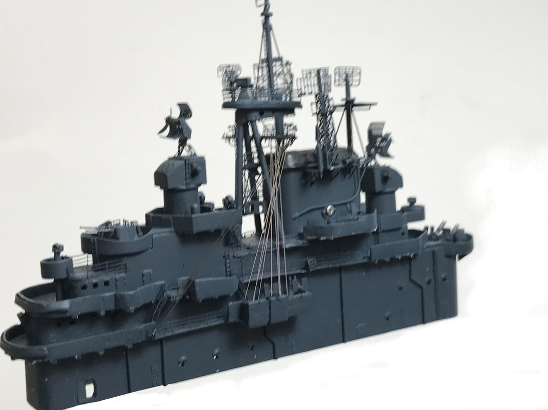
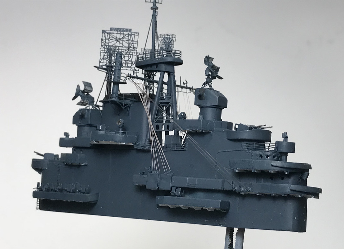
Today was one of those milestone days… the island is now part of the ship and it really looks like an American aircraft carrier. Before placing it I finished the starboard side rigging and as predicted, it took 1/2 the time that the first side took and came out better. Wish I had another side to do. Unfortunately, I can’t redo the port side because I CA’d the pulleys and would destroy that delicate yardarm if I tried to remove it. Again, only I know the difference. To the uninitiated, they won’t see anything but lots of complexity.
To make a more secure surface to adhere the signal halyards I CA’d a couple of pieces of thin PE brass to the backs of the flag bags. This gave me a vertical (non-prototypical) surface to adhere the E-Z Line. If I was a better planner, I would have prepared those flag bags for receiving the halyards BEFORE that part was glued to the island. So if I ever build this again…
On the Missouri, the flag bags were arranged athwartships so it was easier to drill some holes to insert the halyards and give them a better finished look.
I further prepared the inside chamfer to ensure that the island would indeed attach properly to flight deck. It did, so it was time to glue it down. I used tube cement to give some more working time while I applied the glue on the insides of the island’s lower lip and the placed it down and worked it so it was flush, all the while making sure that I was not applying undo pressure OR pressing on anything that will get destroyed in the process. The results were, needless to say, very gratifying.
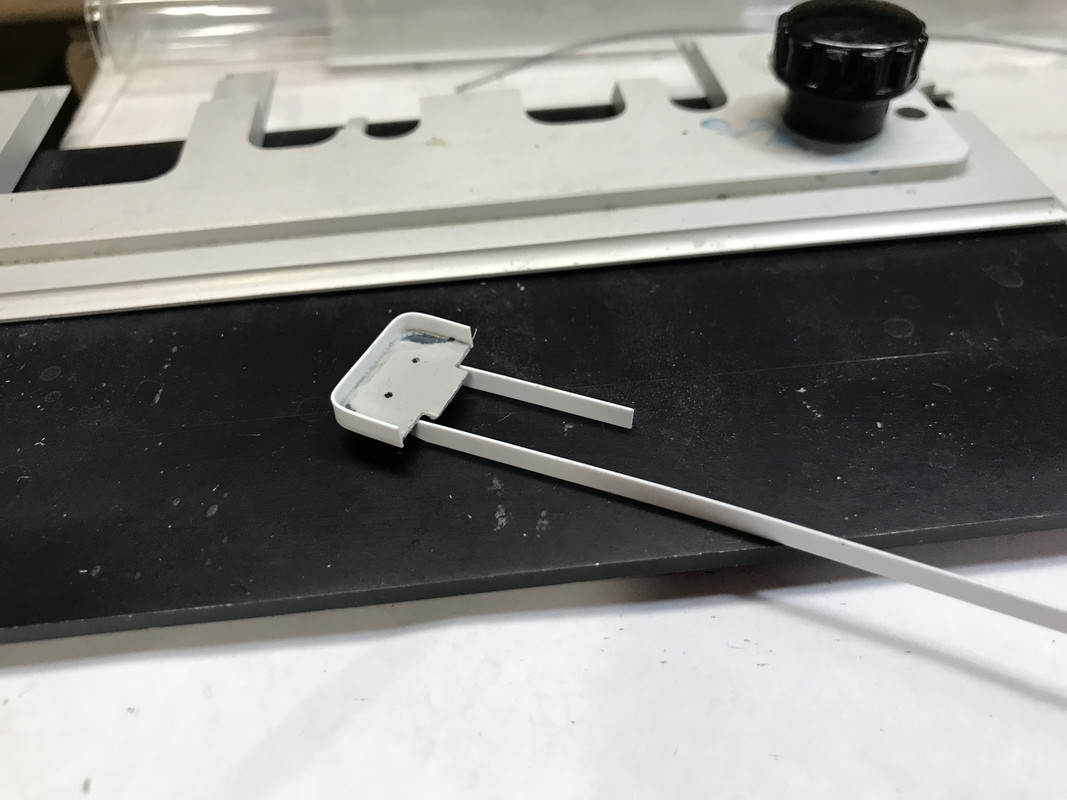
I needed to build and apply the LSO’s platform that sits at the port aft of the flight deck. I had some parts from the last replacement set that GMM sent me and used those. It’s made up of four parts and went together very well.
It still needs paint…
Just about this time, the mail came and GMM’s replacement fret was waiting for me. Oh joy, oh rapture! to quote the Scarecrow in The Wizard of Oz. Here’s what arrived.
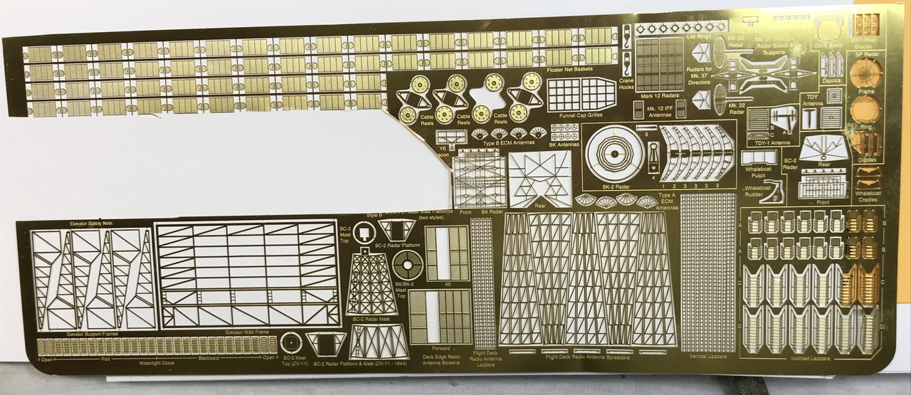
As you can see it’s almost a complete fret minus that part that’s cut out. It’s terrific. It has more ladders, more flight deck ladders (and I need those since a couple have come off), all the radar suite and, of course, the elevator framing and the radio towers.
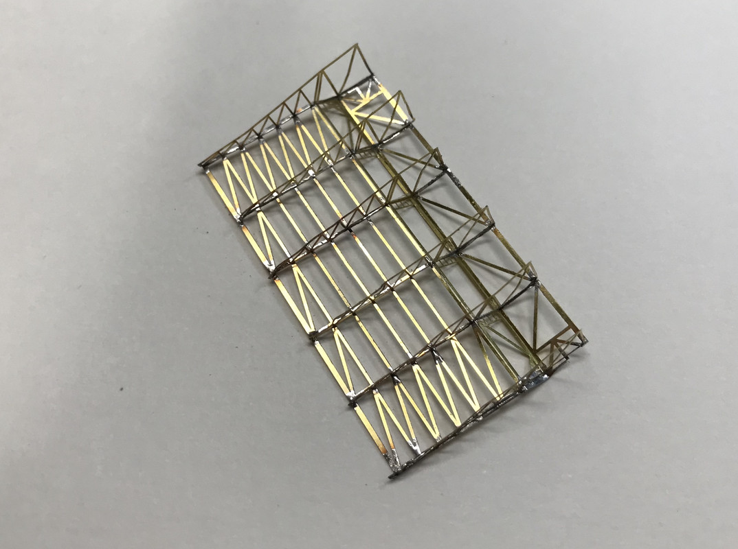
So I immediately set about building the new elevator. What destroyed the last one was when I attempted to fit the elevator into a space that was marginally smaller than the elevator (with its attached brass) and the side pressure deformed all of the brass, popped CA joints and broke some solder joints. The more I tried to straighten it, the worse it got.
This time I pre-fit the elevator without brass to the narrower elevator guide frame. Most likely when I glued on the frame I moved towards each other a bit more than I should have, not knowing what the absolute spacing was. With the elevator relieved to make it a slip fit, I soldered the frame together and gave the same relief on the inside corners, so the frame wouldn’t be stressed when assembled.
As I did before (only even better), I pre-tinned all the mating points of the bottom frame and the trusses using the Weller iron. I then used the RSU to heat and attach individual points on the frames starting in the middle and working outwards. Even with utmost care it was still touch and go. This is caused by the RSU heating the brass so fast that it takes it above annealing temperature and the brass becomes really soft and gets out of shape even easier.
You can use CA all you want, but on assemblies like this solder is so much stronger. To attach the frame to the plastic elevator I used CA. I primed the assembly with Tamiya primer, and it was ready to trial fit again.
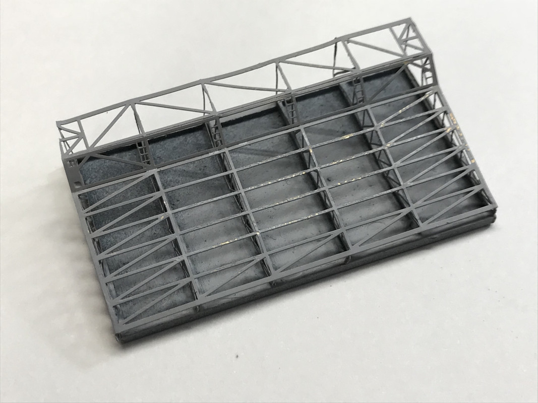
And it fit very nicely without deforming anything. It’s really a benefit to have a second shot at this. Every set of PE should include doubles of everything. I’d pay a few $$$ more if they would standardize on that. Unless you’re really good, you’re gonna screw up some PE, especially on a job as complex as this one. It still has to be airbrushed Navy Blue before I glue it in place permanently.
The last thing I did today was place two tiny TBS antennas onto tiny stalks on the yardarm. These pieces had fallen off the original fret, but there was a set on the first set of replacements. I wasn’t going to put them on because they had a tiny hole that fit over a tiny pin and I didn’t want the aggravation. I also was convinced that due to their frail nature, they would surely be wrecked in handling the island. But with the confidence boost from threading all those tiny eyes with the flag halyards, and with the island being now part of the ship and no longer being handled, I decided to give it a go.
The first one went on very easily so I thought it was a piece of cake. But of course, the second didn’t go on and the CA dried making the pin too fat to get into the hole. So I had to carefully pop the cured CA off the pin by using a tweezer and pulling straight up and it came off without deforming the pin. I was then able to get the antenna onto the pin and they were both done. The arrows point out these antennas.
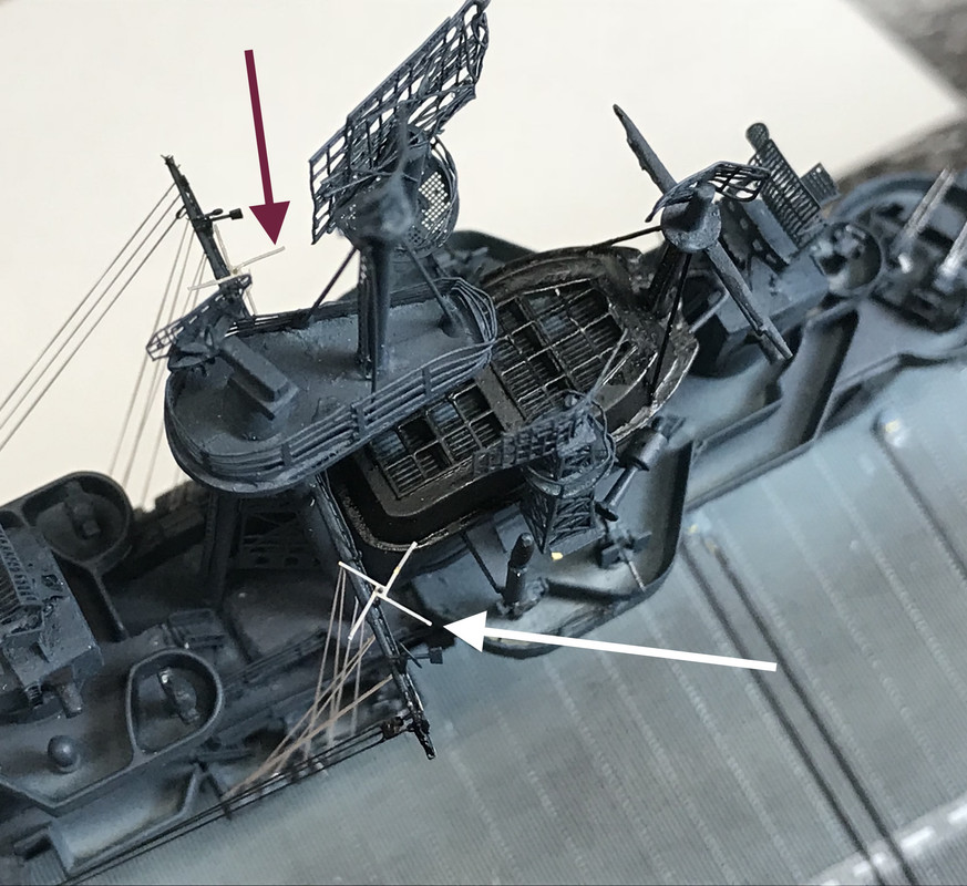
These two also need some paint. Would anyone miss them if they weren’t there. Nope! Do they add to the already wonderfully complex appearance of a WW2 capital ship. Definitely yes! There’s actually two more antenna that go onto the yardarm which look like little steering wheels. I may or may not put them on. They’re really small.
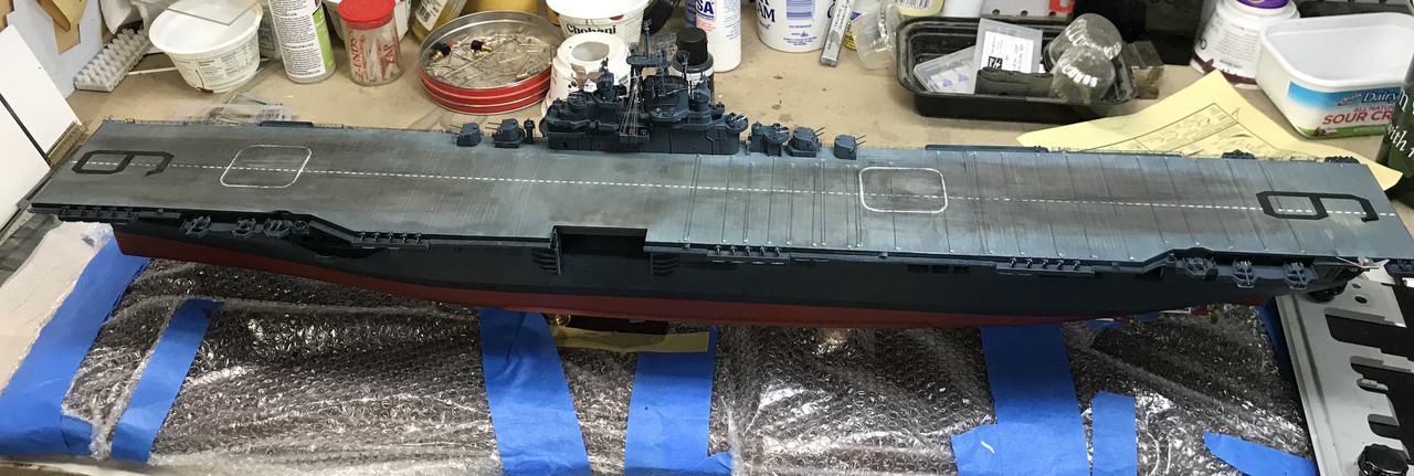
Here’s an overhead shot showing the ship with the island in place. Look’n like an aircraft carrier. Next work day… paint and install elevator, build the new radio towers, install the remaining 20s when they come from Free-Time Hobbies, and add a zillion floater net baskets which I even have more of with this nice shipment from GMM.
I still haven’t decided how I’m going to fasten the air wing to the flight deck so they won’t come loose when they’re not supposed to. If I really wanted to be goofy, I could use E-Z Line and actually tie them down to the deck. It would look great and drive me to an institution in the process. I could use some ideas from the gang on this.
Happy Monday! Unlike most mortals, I like Mondays since it when I can get back in the shpp and build models. As a retiree, I made a deal with my wife that I would not work on models during the weekend, and I keep my deals. So… my fun begins on the weekdays. When working, of course, it was just the opposite.
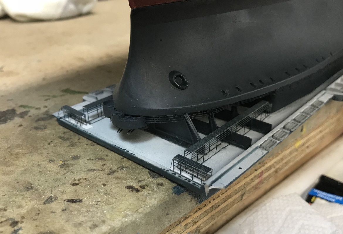
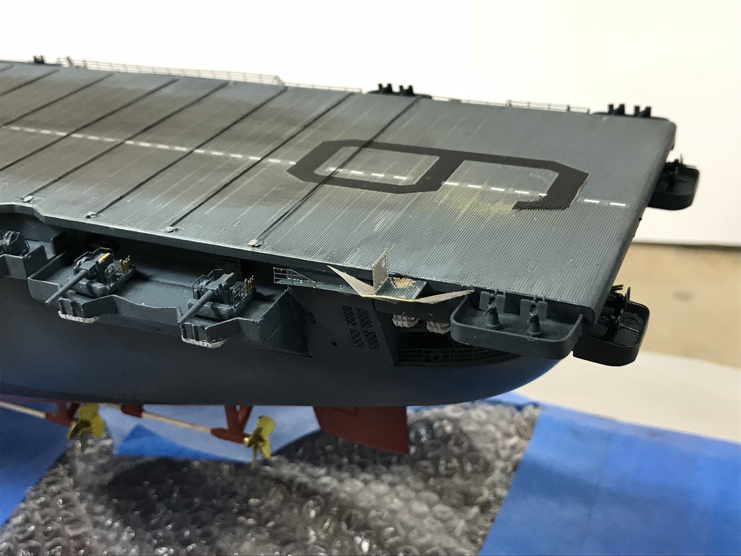
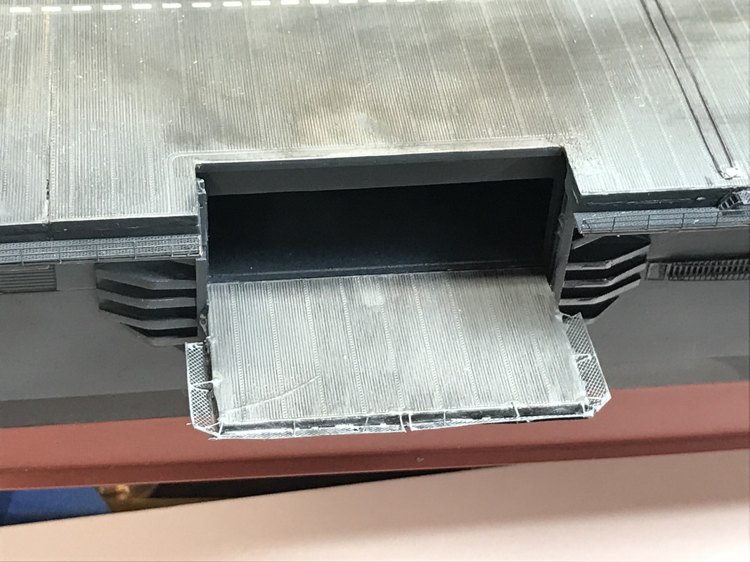
I added to the newly re-built elevator the safety screens AND the ridiculously finicky horizontal braces. There are miniscule PE pieces that get glued between the upper edge of the elevator to the leading edge of the canted screens. I used Bondic for this since it sets solid in a couple of seconds by UV light and not CA accelerator, meaning… once you have it positioned you don’t have to physically get near it to set the cement. It worked pretty well.
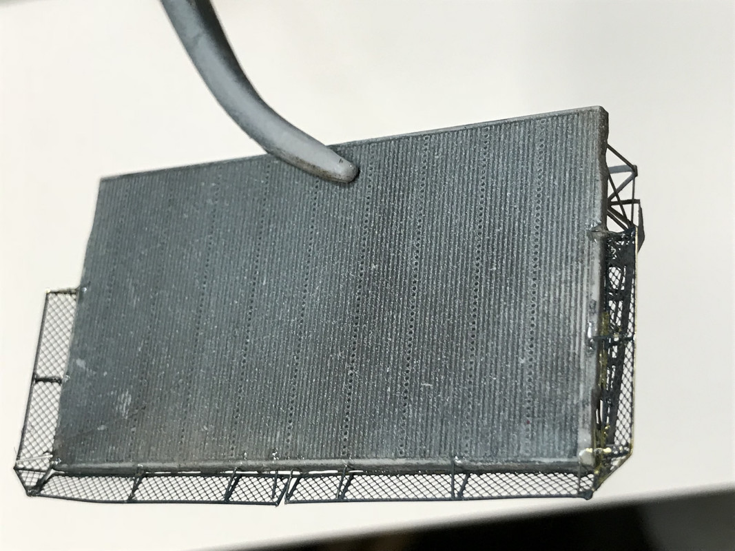
It looks pretty ragged in this ultra closeup, but it views better from normal distances. I stuck the upper side to some masking tape and primered and then airbrushed it navy blue. Then I dropped it on the concrete when separating it from the masking. The drop didn’t do terminal damage, but it did disturb some of the lattice work and broke loose some of these finicky cross braces. I got it back in shape (mostly) and sprayed the upper side with flight deck blue and weathered it lightly with Vallejo dark gray wash. I put it on the hull with gel CA.
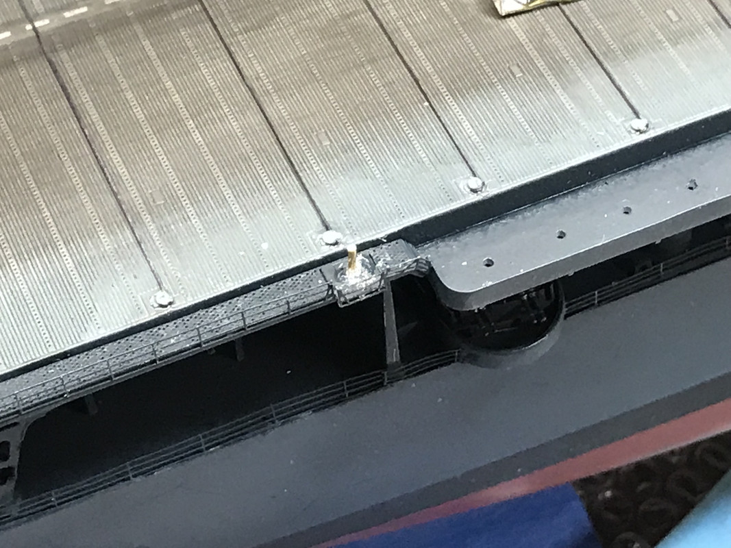
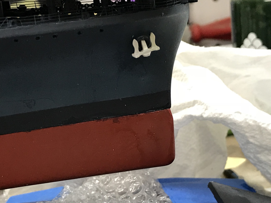
With the elevator finally on the ship, I did some other stuff. I got the anchors mounted. I drilled the hawse holes first so the anchor’s shank would nest up inside. The way the anchor glued on without drilling really wouldn’t have worked. I will paint and weather (rust) soon.
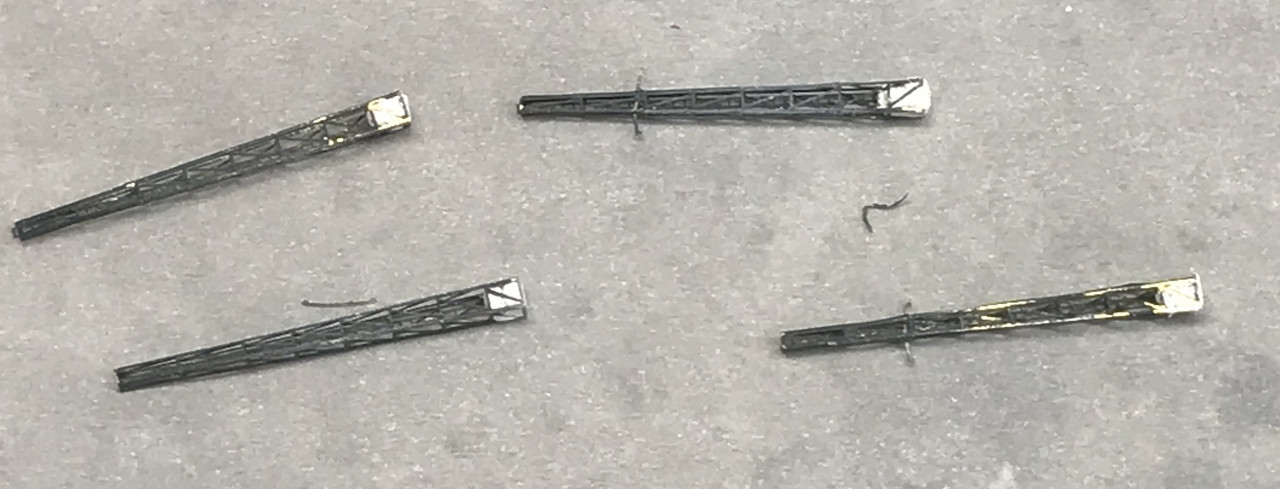
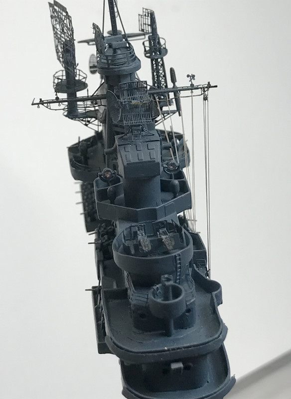
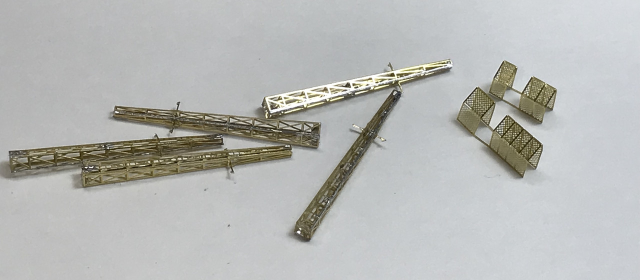
Finally, I built all five long-range radio towers. This time, I pre-tinned the mating edges to facilitate soldering them together and then also soldered the vertical ladder to the tower. I did not, however, solder the tiny antenna spreaders. In this case I used a combination of gel CA and Bondic UV. I wish I could solder them, but they’re just a little to small and difficult to contain to make soldering a useful approach. I don’t trust the glue since E-Z Line does exert some tension which could break them loose.
The last thing I did, which I learned in the first, aborted set, was to fill the bottom with Bondic (not epoxy putty) to prepare for the drilling and subsequent mounting on the ship. I just filled the bottom with the Bondic and shot it with the UV light and Poof!, solid plastic bottom. You can barely see it in the pic since it’s very transparent. I also folded the protective screens that surround the towers with the radio leads heading downward. These parts were wrecked on the first sprue because they had disconnected before I was ready to use them.
The Bondic is terrific stuff and I’m glad I finally discovered it.
Next session: These antenna towers will get painted and installed and then I’ll be ready to rig them. Although there are tiny eyes in the spreader bars, I’m not going to attempt to thread them, but will attach the E-Z Line around them. I think I got glue in some of the and it would be very hard to successfully remove. The extra 20mm guns arrived today so they’ll also be installed. That leaves floater net baskets and some minor weathering, and the ship will be done. In this new set of PE from GMM I have another full load of floater net baskets so I’ll be able to do the whole enchilada.
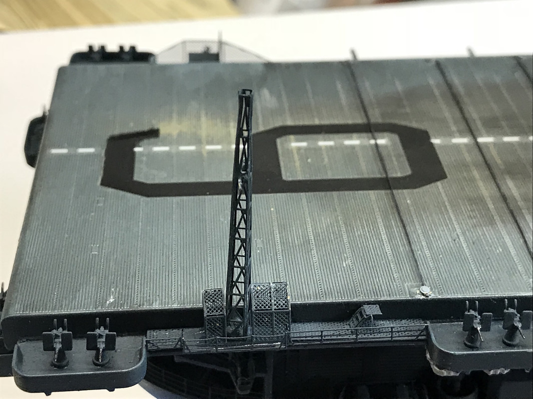
Got the Radio Towers installed today without mishap. Sometimes it’s really good to get a do-over. This was one of those instances. The previous PE got so screwed up, that it reached the point that none coulld be effectively used. One got totally lost, 3 were distorted and the Farraday Cages (I think that’s what they are) screens were ragged or completely destroyed. This time, I was able to carefully build them, keep the fret from getting damaged, paint and install them so nothing got damaged.
I drilled the hardened Bondic plug with the carbide 0.032" bit, but realized that the 0.032" brass rod that was already glued into the catwalk was not a slip fit. It was pushing the last batch over that pin…forcing I should say… that caused all the distortion. So I went back and re-drilled with a bit that was a few thousandths oversize. I used gel CA which filled the space and gave full support. I pocked some round toothpicks into the holes and painted all these parts, first with primer and then a couple coats of force-dried navy blue.
I was concerned about slipping the Farraday Cages over the towers since they could damage those delicate antenna spreaders, but there was sufficient clearance to carefully maneuver the cage around the installed tower and glue it down. I thought about putting the cages down first, but was concerned about getting the glue onto the pin or damaging the cage.
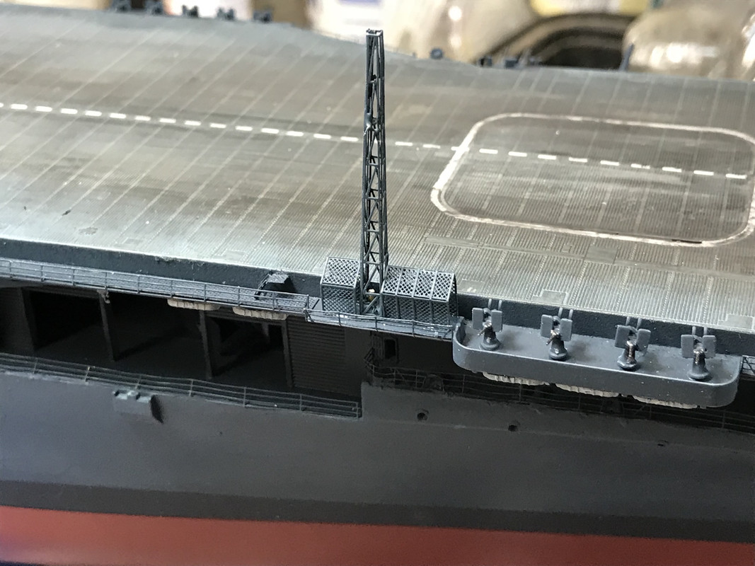
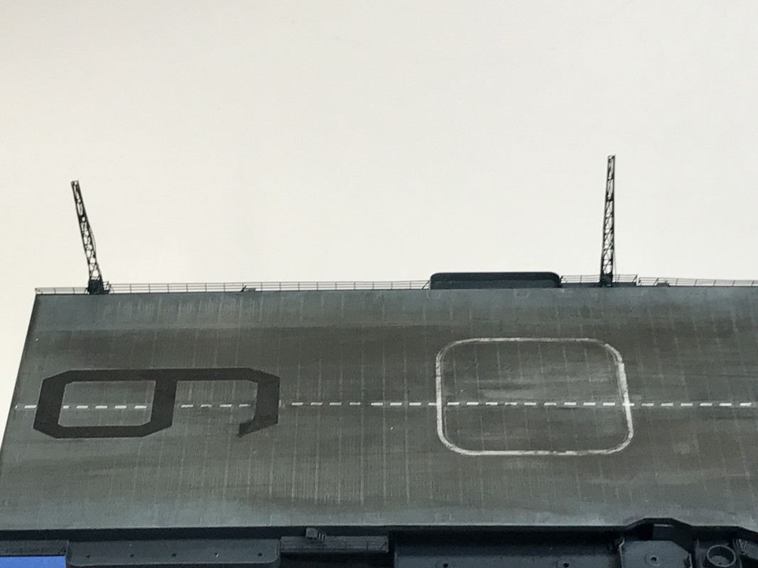
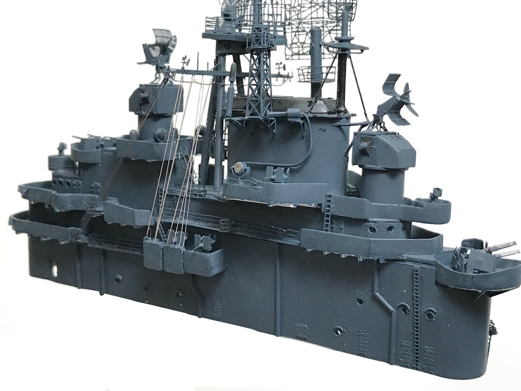
Here’s the front view showing an array of towers. The ship’s too long to get full views without losing a lot of detail.
 While most of the Essex class lost some or most of those antenna towers, the Essex herself, kept all of them for the duration of the War. I thought I could get away with installing less thinking that the Essex didn’t have them all, but that was not the case. The ship was not cooperating. I had screwed up so many that I was hoping that I could authentically leave some off. Now, with the new batch, I finished the ship as she should be.
You’ll notice in the above pics that all the slots are filled with 20mm guns. I also primed and painted them today and installed all the rest. The ship now has it’s full compliment of armament. I painted the anchors and will do some minor weathering tomorrow. I got all the frets of floater net baskets (from now on FSB) painted and will be ready to fold and install them next time also. I have to put small end railings at the ends of all the open catwlaks and I keep forgetting to add a tiny railing leading to the boat deck on the port side.
Then I’ll rig the long-range radio antennas and putting on the air wing. Saving that for last because it will be in the way and surely get whacked. And she’s done.
[/quote]
It looks pretty ragged in this ultra closeup, but it views better from normal distances.Then I dropped it on the concrete when separating it from the masking. The drop didn’t do terminal damage, but it did disturb some of the lattice work and broke loose some of these finicky cross braces. I got it back in shape (mostly) and sprayed the upper side with flight deck blue and weathered it lightly with Vallejo dark gray wash. I put it on the hull with gel CA
[/quote]
The elevator safety nets abord ESSEX when I was aboard (and most carriers I ever saw) were always bent up a bit. Ladder rails, railings, just about anything that could be bent, was bent a bit. To my eye, if you are going to go for a weathered look, a few dings and bends look realistic. I wish someone would do a kit hull with the plating “oil canned” a bit, as most ships look that way too.
Your build is looking great.
EJ