USS Essex 1:350 Trumpeter Build

Well… howdy! You can do PE without building brass masts, etc., but… and it’s a big but… I’m trying to build a model that will stand the test of time and plastic masts with plastic cement can break down over time. I also find solder in small junctions has considerably more strength than CA. I do use J-B Weld when I can’t solder and it’s pretty trust worthy too. I also must admit, I am not a very good PE installer. I’m not really very steady. Thank goodness my son is… he’s an eye surgeon. So I wrestle with it sometimes.

Today I built the mizzen mast and substituted a bigger radar system at the top. The one that was supoosed to go there was tiny and didn’t go well. I have this sheet of miscellaneous WW2 radars from Tom’s Model Works and took advantage of it.

I also built the secondary yardarm that goes under this mast. The mast is 3/64" brass rod, the platform was turned on the lathe and the ladder is from my left over Eduard set. The Eduard ladders as narrower and seem more prototypical.

I’m getting really good at making the hybrid yard arms. This was was a piece of cake even though it was a much smaller build than the main yard.

I added a soldered bushing on the mast’s base to increase the gluing area and enlarged the hole in the funnel to accept. I enlarged it a little too much and glued in some plastic filler strips. I’m going to J-B Weld this in place when it’s time to put it together. It also will have guitar string guy wires and will need an outrigger at the funnel’s rear to accept the back guy. Similarly to what I did on the Missouri.

I started putting on the island’s railings and of course, the inclined stairs got a bit beat up. The GMM stairs are particularly delicated and I kept bumping into the their railings. I’m running out of the Eduard version (a little more rugged) and am going to buy more of them. I also lost a few porthole eyebrows and one WTD. I’ll go back and fix these later.

Tomorrow, I’ll keep adding details…

Looking really good, both your Essex and your Missouri.

Enjoying your posts very much. [:D]

Thanks Steve!

I have only one picture today. That’s because things went soooooo badly that one picture was all that was worth publishing.

It all started with trying to bend the stair treads on the GMM PE inclined ladders using an idea that was published on the Ship Modelers Forum. I found it searching to buy more inclined ladders since I was destroying them faster than creating them. I found that GMM sells a fret with just ladders. The idea to bend the steps didn’t work on GMM or Eduard ladders, but was designed for Tom’s which actually makes a provision in the etching to enable step bending. I did have some Tom’s steps, but the fret was badly etched and the details were too thin a cross-section to permit adequate handling.

In my searching for more inclined ladders to scavenge, I found a neat piece of Eduard PE that could be pressed into action as the outriggers for the mizzen mast. I drilled it to accept the mizzen base and then drilled it with a microscopic 0.015" carbide drill to accept .011" guitar string. Believe it or not, I did not break this drill and did drill both holes. Now that I figured out how to take really tight closeups, that guitar string looks huge. It ain’t! The extra solder was deliberate to reinforce the Eduard etched bend lines since I wasn’t bending those angle pieces as they should have been if used as the piece was intened to be use.

When I attempted to solder the mast into this hole, it didn’t take. Furthermore, the yard arm detached. That when the proverbial stuff hit the fan.

As I messed with the yard arm, the PE laminate started separating and it was getting munged up pretty badly. I decided to remove the bad PE and use the other yard arm PE that I had. When GMM sent me the new main yard PE it was attached to part of the fret that also had the smaller PE yard arm. I soldered this onto the existing made yard and then went to solder it to the yard arm. Oh… and the ladder broke off.

Each time I attempted to solder the yard on the mast had a problem. They were (and could be more than one problem at a time):

  • Off center
  • Canted
  • PE not oriented correctly vertical
  • PE separating from the yard arm

I tried to put this together four times (at least), and of course, the PE was getting munged up like the first one.

Then I tried to free hold the assembly in the RSU’s tweezers to just heat it enough to move the yard to the correct orientation, and the whole deal flew out of the tweezers. I found both parts. Then in another attempt to hold the mast in the tweezers since the platform at the top had re-melted and was now canted, and the mast flew out of the tweezers again, and the sound I heard from across the shop was the sound of a piece of brass entering the quantum rift. I wasn’t able to find it. I’ll find it where the radio tower ended up.

So now I’m starting all over again. This time I won’t have PE to add to the yard, but I’ll figure something else out. All in all, an almost totally frustrating day. You have them sometimes.

The nice thing about scratch-building is that when you really screw something up you have the abilty and where-withal to make it again, and that’s what I did with the mizzen mast. This time I formed the yard out of a solid piece of 1/32" brass square stock. I clamped the piece in a vise grip and ground the tapered portions with the 1 inch belt sander and then finished up by hand. The mast was made the same as the first on with one exception, I turned the base to be a tighter fit in the hole drilled in the funnel.

To solder the yard in place I clamped the mast to the solder pad and went at it with the RSU. Again it took 3 tries (at least) to get it centered and square to the mast. But this time, the solid bar without the PE was a bit easier to manipulate. That being said, I also soldered a piece of bent 0.011" guitar string underneath to act as a place to belay the flag halyards that go up to this mast. That piece of wire was a pain. It de-soldered a few times, got lost 2 times (made new ones) and finally got it to behave.

The first time I soldered it with TIX, but TIX seems to have a problem. If you get the joint soldered right the first time, it holds nicely. But if it breaks away and you try to resolder, it seems not to hold at all. I tried several times to get it to work, and then reverted the Kester soldering paste which is a higher temp solder. I was reluctant to use a higher temp since I didn’t was to de-soldered the platform, or (and this would be worse) de-solder the radar screen. To help forestall this, I clamped a spring tweezers between the heat and the screen to act as a heat sink. It worked. It never de-soldered through these multiple attempts.

I added back the ladder and the base using CA to not tempt the fates and keep the soldered stuff soldered.

It looks kind of crude in this extreme closeup. Since it about 1/4 this size, and painted it will look okay. The Missouri’s masts looked the same before they were painted.

Next up I’ll be finishing up the railings and steps on the island and then start putting it all together prior to painting. Glad to have this mast finished. I wasn’t happy on Friday.

A pretty good day…

All work was entirely on the island. I added some Eduard small ladders to a step on the upper decks. Eduard PE instructions are among the best (if not the best) so I printed out their Essex set’s instructions to use on this model. Their set is for the Ticonderoga, but much is very similar. I had these small ladders left over from the MO, but they were still too long so I cut them shorter.

I made some long platform railings using GMM’s railing stock and some PE Fret brass from Tom’s MW. I soldered the two together and then CA’d them to the island.

It should have been one long 8-section railing. I made a 4-section railing set and then checked my photos and realized that the catwalk went all the way to the WTD on the island side. I then made another 4-section piece. As it is, I would have had trouble soldering that long of a railing to that long of a walkway. There is a loudspeaker that goes right in the middle of that rail which will hide the joint between the two.

I changed the contour of the left most ladder way since it didn’t allow a GMM inclined ladder to correctly sit. I took off part of the plastic rail and then widened the space and put a newly bent ladder in. This worked much better and cleaned up a mess.

I decided it was time to add the mizzen mast and its guy wires since it would take some manipulation and I didn’t want any more stuff in the way.

I glued in the mast with thin CA and then back filled with medium CA. After it kicked, I built the outrigger out of 0.021" and soldered it using the RSU plus standard 60/40 rosin core solder, held in place on the soldering pad. It was an easy build and believe me, I needed an easy one. I cut the legs to length and drilled the funnel with a #75 carbide drill for the three legs. I angled all three holes to correspond to the legs’ angles.

I glued the outrigger in with thin CA.

To hold the guy wires (high E guitar string - 0.011" dia.) I used a divider to space out their locations and drilled with a 0.0105" carbide drill. This drill is so small that if you pick it up the wrong way, accidentally touch the side of the drill, or drop the pin vise on your leg, the drill will break and disappear. It will also put a needle injury on your thigh. Ask me how I know…

I put a kink in the bottom end of the wire, fit it in the hole and then cut the length so it tucked under the platform on the antenna mast.

I used this length to approximate the length of the other foreward guy, and then used J-B Weld to glue them in place. I put a kink in the bottom of the rear guy so it would sit flat on the outrigger, measured its length and glued that in place also.

This all has to cure overnight. Tomorrow, I continue detailing the island and get ready to start adding the big assemblies before painting.

The Island is coming together… in fits and starts, but it is getting together. I first added a very small rail at the stair landing at the top of the left most ladder. I find that small rails like this, instead of being easy are a royal pain in the butt. They’re very springy and if you grab them the wrong way they fly. They also want to glue too quickly before they’re sitting just so… and then when you just want to tweak them a little teeny bit, they fall off and you have to start over again. I did that five times before I got one to be where I wanted it without being a distorted mess.

Boy, these models are not meant to look at this closely…

The J-B Weld cured nicely for the mizzen mast guy wires so I was ready to start adding more stuff. Next up was the whistle platform. In this case, I soldered a piece of flattened 0.021" brass wire for the mounting pin. I also did the same on another small antenna platform. I am so glad that I spent the effort to add these brass pins to the PE platforms. The angle brackets are useless, and are almost always bending and breaking off. You CAN NOT DEPEND ON THEM TO ACTUALLY SUPPORT THE PLATFORM! The whistle was scavenged from the old MO and I drilled the back of it to accept a piece of fine gauge solder that simulates the steam line to the whistle. I the line originates in the funnels fore port side. I can probably dress that line a bit better.

And then it was time to add all the rest of the antenna systems. The SK’s railing was a mess and was interfering with installing it properly. I trimmed away part of the funnel top plate and then re-arranged the ends of the railings to wrap onto the funnel. It’s not great, but cutting the GMM rails in the middle creates a non-controllable mess with the three bars just flopping around. It doesn’t work. And I’ve tried soldering another vertical post in the middle to give a shorter section. It didn’t work, but it could. I just have to perfect it a bit. CA’ing the vertical is a non-starter. The 0.032" pins worked, but they were a bit of push into the holes which worried me that I might use too much force, slip and screw up several hours of work on those antennas.

The tri-mast went in without a hitch. And I added the piano wire guys to that top mast on that platform too. I didn’t attempt to drill any tiny holes in the brass. All that would have done was break a $1.50 carbide tiny drill and probably destroyed some antenna or another, so I just placed them there and will led the J-B do its stuff. It’s starting to look really cool especially if you don’t dwell on all those twisted railings. When it’s painted and rigged with radio wires and flag halyards it’s going to be very convincing.

While the J-B was setting up, I started detailing the structure that sits directly aft of the island: a two-deck tower that supports a 40mm quad gun tub and director. My research shows a couple of vertical ladders, a WTD at the 2nd level, and a landing and inclined ladder at that door. I was having a time making the small platform, again because you can’t really have GMM rails in half-sections. I get this finished tomorrow and show it.

After sleeping on the problem of making that little ladder platform, I did attempt #4. This time, I did two things differently: I found a piece of railing in the leftover Mo set that was a short railing with another even shorter segment. And then I shaped a brass platform to match this configuration. I also added to folded angles to act as brackets to increase the gluing area many fold and solve that problem of not relying on the railing itself to aid in gluing. This closeup makes it look terrible. It’s really not bad…a little off kilter, but it will work. The inclined ladder has to go on after it’s glue to the deck… I think. I may want to glue it on now so I can paint it before installing it.

I then added the 40mm gun mount and the MK 51 director so this piece is ready for paint (except for the aforementioned inclined ladder).

The latest guy wire gluing went well too with the guitar strings firmly attached to the mast and deck. I then decided to add the wind deflectors. The GMM wind diflectors looked to me as a complete exercise in futility. It consists of some etched strips with little relief cuts and then a ton of little pieces to serve as the supports. I cannot, for the life of me, figure how to a) attach all those parts without going nuts, and b) then bending it around the deck rails and glue it in place without all of those tiny pieces breaking loose. I thought about soldering them in, but I’m not that good.

This image is bigger than it actually is. I can even imagine cutting all those pieces off the fret without losing half of them to the Rift. Sometimes with PE, just because you can draw it, expose it and then etch it, doesn’t mean a mortal (like me) can build it.

So I did a plan B. You can really see the slats holding it on, so I took some wine bottle foil and a piece of 0.020" Evergreen round styrene rod to use as a spacer. I measured the PE strip at 0.037" and used the same digital caliper to scribe a line of that distance on the foil. I held a straight edge up to that line and CA’d the styrene to the foil, BEFORE CUTTING THE FOIL STRIP since I could not imagine getting the two aligned with that wiggly, strip moving all around. When the CA set I then cut the foil with a sharp #11 blade and the same straight edge.

By using the styrene as the spacer I was able to use Tamiya cement to glue it to the ship.

A little forming and shaping was needed once it was glued. Again, once it’s painted it should do what was intended.

Lastly, I started laying in all the added stuff on this complicated sub-assembly: Mk 51 directors, signal and search lights, MK 38 directors, 40mm guns, etc. Starboard Side -

Port side -

I did straighten out the steam line to the whistle. There’s also a smaller diameter pipe going to that same area that I may add. Still to do are all the 20mm gun sets for the island (and the rest of the ship). One of the side-of-funnel searchlights is missing. There were supposed to be two of them, but the sprue attachment was very weak on these parts and both fell off (one of each of two identical sprues). I captured one for safe keeping, but have lost one. I’m going to scratch build one. If it works well, I may scratch build both. It goes in that sponson with the half railing next to the funnel.

I almost had a heart attack… notice how close my outrigger for the mizzen mast aft guy wire is to the Mk 38 director aft of the funnel. It just fit. In real life this outrigger would have been much, much smaller. I could have made it smaller since I was just winging it. I didn’t even think about the director going so close.

I’m going to paint and detail all of this before gluing it to the deck. I may also add all the rigging that is contained within the island since it’s much easier to do this while holding it my PanaVIse than to do it leaning over the ship.

Spent a lot of time today making some very small things…

I made another searchlight to replace the one that’s missing. I turned a cylinder the diameter of the prototype, 36" = 0.100" approx. at 1:350. I then turned a pedestal. This came out nicely, but as you’ll see it’s a bit tall. I could have made it shorter, but didn’t feel like making another. The only way you know is if you look at the ship head-on and see port and starboard lights at the same time.

Before parting the cylinder off the stock, I took it out of the lathe, put it in a v-block, filed a flat on the circumference so the center punch and drill would skitter off the circle, and then drilled with a 0.032" carbide drill in a pin vise. I had to drill through the center hole and had to be careful to keep it aligned and not break it. I use Tap Magic for brass when drilling and turnind which helps prevent grabbing which is notorious when machining brass with positively-raked cutting tools. Normally, brass tools are ground with 0 or negative rake angles to scrap the surface rather than cut into it. The rake angle is the back slope of the cutting edge. Positive rake has an acute angle falling back from the cutting lip. Even with drills, if they’re large enough to do this, you can grind a small flat behind the cutting edge to reduce the rake angle.

I made the bail with a piece of PE fret brass and turned the base with a 0.032" base pin and pin for the bail. I needed to set the hole spacing for the trunions. The cylinder was .100", and the trunion pins would lie on the diameter, so I multiplied .100 X pi, and then cut that in half and added 0.020" for some clearance. I could have added more, but the bail did fit over the pins. After soldering it all together, I trimmed the bail and filed off the trunions. I filled the center hole with solder to make a face. I was going to leave the hole, but the trunion passed through the middle.

Here’s the installed search light.

Next I built the GMM PE loudspeakers. They’re a three-part affair with a folded box, a perforated screen and a small folded bracket. I decided to solder these together after messing around, unsucessfully, with CA. The first one I made (which eventually flew out of a tweezers into the Rift) I soldered the screen and then attempted to solder the bracket. This was a mess. The next one, I soldered the bracket first and then soldered on the screen. This worked. But I lost a couple of the brackets, so the next two I made a bracket with a strap of PE brass. This actually worked even better. You can’t see that microscopic bracket anyway.

So I only had three of them at that moment. I CA’d the first one to the front wall of the flag bridge as shown in one of my diagrams. The other goes on the rail in the island’s middle. This didn’t want to settle down with CA, so I went with J-B. Since it sets very slowly, I laid the island over almost horizontal by swiveling the Panavise base into that position. It will be cured on Monday when work begins again. You can just see it below the radar antenna racks facing upward. The 3rd loudspeaker, which was supposed to go on the aft end of the island, flew out of my tweezers on the way to put some CA on its bracket and went into the Rift.

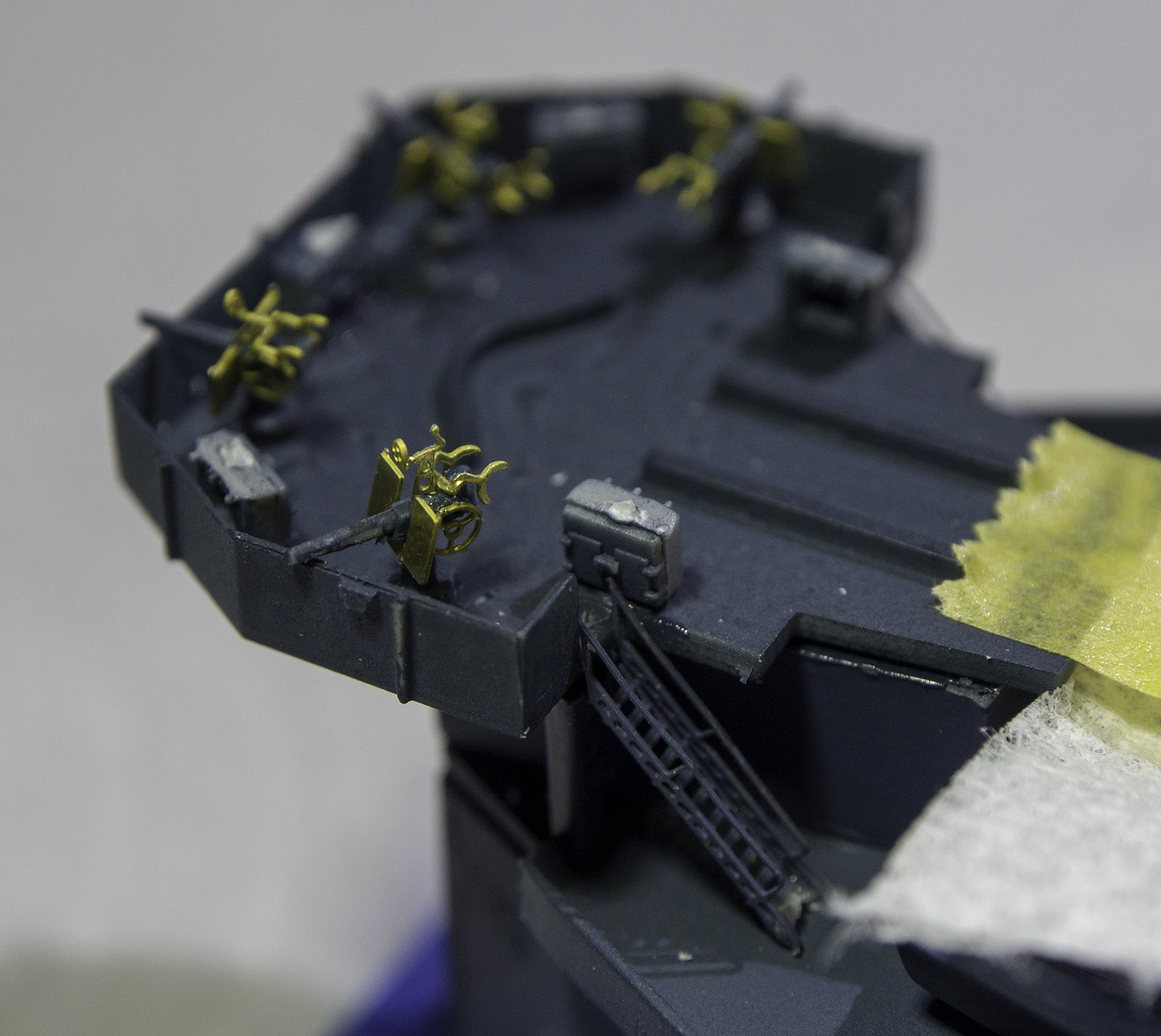
I started building the 20mm gun sets. GMM includes four PE pieces for each gun: shield, shoulder rests, gun sight and elevating wheel. Of these, the easiest to install was the shield, but I did have to rough up the brass at the glue site to give the CA something to stick to. I also put on a set of shoulder rests. I tried, successfully at first, to install the tiny gun sight, but it fell off and then got lost. I also tried to install the hand wheel, and it too fell off. So it took quite a while to get one done. I got the second one underway before dinner time. I’ve got to build 13 of them just for the island. I have a full set of 20mm PE guns left over on my MO Eduard set. These are a folded deal that already includes the shoulder rests, but lacks a base. The base pin is about 0.020" and could work (maybe) with the Trumpeter bases, or I could just turn a set of custom bases and solder the whole deal together including the shields. I have to think about this over the weekend.

That’s an #11 blade in the picture for scale comparison, so you can get a good idea about just how small that gun site is AND you have to rotate the circle site so it’s perpendicular to the barrel. It just has that tiny base to hold it to the gun barrel. It’s not a pretty thing and I’m not so sure it will be successful, at least for me. I am sure there are builders some where out there in this wide world that have the steadiness and techniques to build these micro-PE assemblies.

Here’s the completed one. The Trumpeter barrel is WAY out of scale. The Eduard ones are much closer to scale, but they lack that base. Nothing’s perfect. I’ve looked at some of those Korean and Chinese PE company products which have turned barrels and so much detail, but I can’t figure out how you’d build the darn things. At 1:200, you’d have a chance, but at 1:350, it seems almost impossible, based on my experience.

Builder,

Thanks for posting all these details shots and telling what you are doing. They really are a help! It is times like this that I wish I had taken shop in high school! I really need to bone up on my so “called” soldering skills.

I hope you’re feeling better after your fall.

Steve

A lot of nice metalwork there.

I taught soldering to about 2,000 people with some significantly positive results, so I could put together a pretty good tutorial on the subject. There’s lots of soldering clinics on YouTube… some good, some dead wrong. You have to separate the wheat from the schaff.

I did an article in Classic Toy Trains in November 2001. It was the cover story. It was mainly concerned with doing effective soldering of power leads to model train tracks. For soldering PE, the techniques and tools are somewhat different. I’m still developing techniques for this, since PE, by its nature, is very delicate and tempramental. (this site doesn’t have a spell check, and I think I spelled that wrongly).

You may wonder why a whole week went by without a post on the Essex. I had a stomach (intestinal) flu that was quite strange in that it was all cramps and nothing else. No nausea, diarrhea, vomitting… nothing. But the pain was significant and annoying and I didn’t feel like sitting in the basement building those %@(*% 20mm guns.

So instead, I decided to trade my time and frustration for $$$ and bought some new Blue Ridge Models 3D printed 20mm single gun mounts which include nicely formed barrels, shields, shoulder rests and ammo cans. They come 24 to a rack so I bought two. I’ll just have to add gun sights (if I want to) and I’ll have nice, scalish 20mms. I would have spent the entire week building the others anyway, so I probably didn’t lose much productivity.

These things should work pretty well. Painted, they will look terrific. I can see you have to very, very careful cutting them loose from all the 3D supports. They’re not cheap at $20 per unit, but I spent that much ($40) for the 3D printed architectural details for the Bronx Building, so I guess that’s not too bad.

As a result, I was looking at what it would take to have my own 3D printer. There is such a variety and now that the Chinese are flooding the market with functional filament deposit machines, there’s a lot to choose from and a huge price range from less than $200 to multi-thousand and still be 100 micron resolution. I feel that for 1:48 work, you probably need 50 micron (or less). For 25 micron, you at the limit for filament machines and probably are looking at stereo lithographic ones. They are dear ($3000+) and are out of my price range by an order of magnitude. I’m not looking to make trinkets and curiosities, but want to make real functional parts for buildings and models. For instance, it would be great to print the two turret domes for the Nighthawks Cafe and not have to attempt to turn them on my tiny lathe.

There is a maker’s club in Louisville that has 3d printers and laser cutters to use, but it is a $50 a month membership. I’m not happy with that and would have to think seriously about spending a third of my hobby budget just on the membership.

On the other hand, I’m not looking to get into another hobby. I don’t want to buy a tool that has a steep learning curve and intensity requiring all that attention and experimentation. And, while I have all the skills to build a kit printer, again, I’m not sure I want to take the time.

I’ll take some feedback on this…

Meanwhile, my alimentary canal is working normally. I had a blood test to rule out any pancreatic or gall bladder nonsense and the numbers were all perfectly nominal. So it was just a bug, and a strange one at that. Tomorrow, I’m back in the shop.

Back in the shop! Whoopee!

And the Blue Ridge Models 3D printed resin 20mm gun mounts arrived today. I had already started back building the modified kit guns, went upstairs for lunch and my wife said I had a small box arrive.

Here’s another closeup of the array. They’re held to the base with 6 supports.

They’re very, very delicate for two reasons. First, they’re very small, and second, they’re resin which is brittle. If you clip the supports with too much force, stuff can break. If you grab then a bit too hard, stuff can also break. I had some trouble with the shoulder rests and lost one side on three of them. I also broke the splinter shield on a few which I replaced with PE.

This is a telling shot. It shows the PE modified kit guns with their “massive” gun barrels and the complete 3D printed one. It was worth the $40 already in that I installed all of the guns in the island in the time it would have taken to cobble together two more mounts. And there’s really no comparison about the overall effect.

Being resin, you must use CA to install. I finished up the island in a couple of hours.

In this next picture, you can see the ones where I had to replace the shields. I didn’t want to scrap them becuase I’m going to need every one. The GMM PE shields are a bit shorter than the 3D printed ones. Will it matter… I don’t know. Right now with the brass shining away, it’s quite obvious, but when all paint navy blue, you may not notice the slight size difference unless someone told you.

You can also see those with missing shoulder rests. As I get more experience in preparing these little pieces and should break less of them.

On one, I broke off the tiny barrel. I drilled the stub with the tiny, 0.0105" drill and inserted a piece of guitar wire which was just about the right diameter. It was a bit long, so instead of pulling it out, cutting it and putting it back in, I (stupidly) tried to cut it with the Xuron hard-wire cutters and the shock broke off the gun top from the base and sent it into the Rift. I was left holding the base in my locking tweezers. Next time, I do it right. Incidentally, don’t ever attempt to cut guitar string with normal Xuron cutters. You will be left with two half-moon grooves in the edges and probably an un-cut piece of wire. (experience talking here. “Good judgement is the result of experience which is often the result of bad judgement.”)

The island is finally ready for a final cleanup and paint.

I’m going to start building the flight deck. Instead of putting the three pieces onto the hull separately, I’m going to fully assemble it with reinforcement at the two joints. I started prepping the joinery before the 20mms arrived. I intend on installing LED lighting on it and that has to be done on the total deck. There’s a ton of added detail that goes on the flight deck sides including catwalks, added railings and small steps.

An odds and ends day…

Started by preparing and gluing up the flight deck. There were mold imperfections at the junctions, so even after filing it as flat as I could it still showed some significant gaps. Since I was not putting the decks into position on the hull and was going to be handling the entire glued up deck, I had to reinforce the joints as much as I could using Plastruct heavy H-beams… very stiff and glues well to styrene. When I first put the beams on, I had one in a place where the hangar deck structures impinged with it. I tested it again after I moved it and added another, and that too got in the way. Luckily, the glue hadn’t set and I was able to move it to a better spot.

You can now pick up the deck anywhere and it holds together.

Here are the gaps which I will judiciously fill so they’re be less noticeable. I will mask the deck area when I sand the filler if I need to so I won’t sand off all the deck planking details.

Next up was putting the PE railings onto the 5" single mounts. Funny… it appears that trumpeter made these guns backwards. The guns load from the left side and the rammer wall should be on the right side of the breach area. In this molding they’re on the left side, while the instructions show a drawing with the loaders on the correct side. As it is, the left rail which has the fuze setting machine is on the correct side.

As usual, no mortals will notice this.

Then I modified the 5" twin mount bases to accept a nicely perforated base replacing the thick plastic version. To do this you had to cut the base away from the top and substitute the PE for the removed plastic. I did this using the micro razor saw and then a #11 blade on the inside to inscribe the cut line.

The pin on the mounts was slightly larger than the hole in the PE so I used a #40 drill to open it slightly and the gun fit in perfectly.

There is also one of these screens that goes next to each deck-mounted 5" twin, but first you have to remove the plastic version sticking out from the deck. I didn’t do that today since the flight deck was not securely cured. I’ll do that next session.

Lastly, I built the PE boat crane replacements using my fold-and-solder technique. It’s moderately complicated fold, plus there’s a separate piece that gets curved and installed in the crane’s crotch. I really can’t imagine how unstable this would be if you had to rely on CA to hold it all together, almost all the joints were handled with the RSU.

The PE part to fill that gap was the exact size and it kept falling inside when attempting to solder it. I cut some PE brass slightly oversized and made a lap joint which is much more secure, soldered easily and will not detract from the effect. You’re required to cut parts from the ship’s plastic cranes to mate the PE version to the ship. I’m going to think about this and take a look as some detail pics of the real cranes and maybe do it in brass.

Builder,

I think it’s great that you found those 20mm guns on eBay. I wish I’d found something like that when I was working on my USS San Francisco. Such a PITA to have to put those guns together with the GMM PE!

You did them great! And they are a royal PITA! Like I said, it was worth the $40.

Finished building the hybrid Boat Cranes. GMM calls for removing the base and the upper works. I machined and soldered the bases, but did cut away and CA the upper works to the boom. Stuff actually went pretty well and was not stressful.

The hooks was a one piece PE that is CA’d into a small slot etched into the boom bottom. I didn’t machine the base pin very carefully… it didn’t matter… I just adjusted the hole size on the hull.

Next up was the flight deck. I removed those plastic outriggers next to the lower twin turrents and prepared the edge to accept the folded PE replacement. I also removed some of the alignment ribs under the deck that were supposed to mate with the hangar deck houses. They didn’t fit well and I read a review that said the same thing. It was taking much to much pushing and shoving to get it to sit down and it would mean probably breaking something to get it together.

I used a sanding drum on the flexi-shaft and then cleaned up with a plastics chisel and files.

It fits much better with these guides removed. I’m sure if it was Tamiya or Hasegawa kit instead of an old Trumpeter, I wouldn’t have to do this.

Lastly, I started adding the under-FD details, including some lift rafts and the box sections that support the catwalks. There are ejection pin marks on all the catwalks, but I think they’re not going to be see when the PE goes in. I’m going to add the FD PE AFTER the deck is glued down. There’s too much handling to get the deck in place and the PE would get whacked. I do have to add the forward 40mm mount and director before the deck goes down since it’s really occluded by the deck overhang. That’s the reason why later Essex series ships were built as “long-hull” ships with the flight deck moved back a bit so the forward 40mms had a decent arc of fire. As it is with the early Essex, they could only shoot pretty much straight ahead. You would have thought that they would have seen this in the design phase.

On the hull side, there is a door and a slanted raised rib that corresponds to an inclined ladder that I’m going to install, but I needed to have the FD in a near final form to see if it clears the upper ladder hand rails. I didn’t want to glue this is only to have it crushed when the flight deck goes down. I also need to add the ribbing supporting the side elevators runners and detail the whaleboat.

This was a pretty short session today, but it was productive. Tomorrow I will start adding the lighting, and then paint the interior of the flight deck white before closing the lid.

It’s Sunday, but I’m reporting on Friday’s session…

Filled the flight deck gaps with Tamiya putty. I didn’t want to damage any of the FD engraving so I masked (with Tamiya tape) very close to the gap itself, filled the groove without worrying about the overlap, and when the tape was pulled, it was just in the groove and nowhere else. It just took the lightest of sanding to smooth it out.

There were expansion joints on carrier FDs so these will be those.

I then wanted to attempt to fit the FD to the hull. I spent a lot of time doing this since I wanted to figure out where the clamps had to go, what was impinging on what and planning out how (and when) to do it. I had to remove more raised alignment lines that were going to be a problem. When I got it so it so it would almost drop in place I stopped since I’m gluing it on yet.

It was time to get the lighting in place. Let me start by saying, the end result of Friday’s session is not satisfactory. My lighting scheme is too over-designed and bulky. I’m using CL2N3-G LED drivers to manage the 5 VDC input. These little packages take anything from 5 to 90 VDC and feed it to the LED at 20 milliamps. You can string as many LEDs in series as the input voltage will allow. In this case, I can probably drive 2 in series. They won’t reach full brightness since each LED drops 3 VDC. To run them in parallel you have to gang these devices, since they only put out 20 milliamps. In a parallel circuit with two legs, each leg pulls 20ma, so the total current draw is 40ma and you’d need a driver on each leg.

The input side is on the left side of the flat. The center lead is no used, but supports the package if it’s mounted in a printed circuit board.

I’m using small 2mm LEDs which I wanted to face towards the ceiling and then reflect downward to provide a more diffused lighting. So I drilled 2mm holes in some styrene, and CA’d and then epoxied the LEDs into the position with their lenses through the hole. I put down some aluminum foil with some pressure sensitive adhesive to make the ceiling more reflective. I let the epoxy drill all weekend. It’s a composite picture which accounts for the slight distortion.

So here’s the problem… I thought I needed to raise the LEDs off the ceiling to give enough clearance for the light to escape, which is technically correct, but when I put the deck in place on the hull to see how it all fits, it was terrible. The light assembly is too tall and almost touches the flight deck floor. When you peer inside through the side elevator opening all you see is lighting assemblies. Yuck! No room for airplanes and completely destroying the effect I was looking for.

So what to do? Ideally, the lighting should come from fiber optics (which I don’t have). If I can’t do that, I will probably mount the LEDs directly on the ceiling and have them facing downward not worrying about indirect, diffuse lighting. I can mount the circuitry very tightly to the ceiling so it won’t be seen unless you’re lookin up into the hangar bay. Otherwise, I’m going to scrap the lighting altogehter. I don’t want to invest in fiber optics, although I may research it to see what’s what. Tomorrow, I will rip it all out and go for plan B. With fiber optics, the light box can be below the hangar deck and I could bring the bundle up through the pipe I’ve installed to bring in the power wiring. I think I’m talking myself into this…

Addedum to post: found that I can get 100ft of 1mm fiber optic filament on eBay for less than $10.00 so I ordered some and will give it a try. I found a place called the Fiber Optics Store, which also advertised on eBay, but their website cart was not functioning properly, so I went onto eBay and bought from another supplier. I read a blurb on how to attach LEDs to the fibers using shrink tubing so that’s how I’ll do it. More about this when it comes in a couple of days.

I had a site for lighting that looked like sheet styrene. Can’t find it now but will keep looking.

Found it. Look at these. I’m going to use them in my vintage 1/530 Revell ESSEX in the hangar bay.

http://www.microstru.com/Experimenter-Kits.html

That’s an elegant solution… and here’s another. It was suggested by Ken_NJ, one of my faithful followers on one of the other places where I post this odyssey. It was to use surface mount LEDs soldered to adhesive copper foil. It’s a cheap solution. The LEDs are $0.29 each and 100 ft roll od adhesive foil was $8.00 on Amazon. It came yesterday so I had to test it today. Needless to say, it’s an awesome process for interior lighting. I don’t use the word “awesome” lightly. These things inspire awe!

Their design for machine insertion and soldering, but with careful attention can be hand soldered. The electrodes are on the bottom. The longer one is the negative side. There is a small gap (1mm) separating them. I placed the copper foil on a piece of scrap acrylic about that far apart, tinned a tiny spot onto each side of the gap, held the SM LED in place over the solder pads with a tweezers and heated the foil adjacent to the LED on each side. It took seconds to melt the solder and attach the LED.

Boy! These things are bright. They are wide dispersion (120 degrees) so they’re going to illuminate a wide area. Because of their diminuitve size and the care needed to solder them, I believe you’d have to assemble the circuitry on it’s substrate off the model. You could never effectively solder them in a vertical position. They are meant for machine insertion and automated soldering, but as you can see, you can successfully solder them.

I’ve ripped out all of first attempt lighting on the flight deck bottom and will used this method to illuminate the hangar. It will be bright and the lighting will be totally obscured. I’ll be back on Essex work next week.

Even though I don’t work in the shop on weekends (as a rule), I did get some serious thinking time and I do most of my thinking in either SketchUp or CorelDraw. I drew up a pictorial schematic of the foil pattern that I’m going to use for the SM LED lighting. I can’t mount the foil directly to the styrene flight deck because it won’t handle the soldering heat, so I’m going to build the LED circuit on some thin ply. The soldering is quick, but it’s still hot.

You can see the gaps for the LEDs. I had to work around those big chunk of Plastruct H-Beams that are reinforcing the fragile FD joints. I’m not going to have the five current limiting resistors on the foil. They’ll extend too far into the hangar space. Instead, I’m going to attach the negative leads onto the foil, bundle all five wires together and bring them down the wiring tube and add the resistors below decks where they’ll be out of sight. The ends of the buss bars is where I’ll do a “Burglar alarm window foil turn” which I learned when I was moonlighting as an installer in the 1970. In that case it was lead foil, not copper, but the idea is the same, make a 90 degree turn without breaking the circuit.

After soldering all the LEDs and connecting leads, I’ll glue the ply to the FD styrene. After is glued I’ll liquid mask the LEDs themselves and paint the hangar ceiling and walls white and the hangar deck some other color.

Just what color is the hangar deck? Is it deck blue, or is it some other color and that ends at the doors? Then I’ll join the deck to the hull and continue building.