Steve and I were discussing the pedestal for the gun tub being square; but the pedestal for the director platform is most definately round. That I have actually seen. On the ship today (or when I was there back in the 1980’s) you can’t see the pedestal for the gun tub as it is under the silt that has accumulated there. the silt ‘bank’ starts about even with the forward side of the #3 barbette, and builds up to about 2/3’s the height of the bulkhead at frame 88. Back in the day, with the poor visibility, it looked like the tub nearly sat on the deck, but the director pedestals stick above that.
The 1.1" director mount PLATFORM is 6’ in diameter with an appromimate 2’ diameter base. (Possibly only a 12" diameter. It is said to be a narrow pipe.)
The 1.1" GUN TUB is stated to be on a Square base as in the USS Oklahoma plans.
Based on the Arizona’s 1941 Booklet of General Plans, the measurement for the 1.1" Gun Tub is 14’ in diameter. The existing belief is for an approximate 8’ Square base as in the USS Oklahoma plans and as shown in a photo of USS Maryland.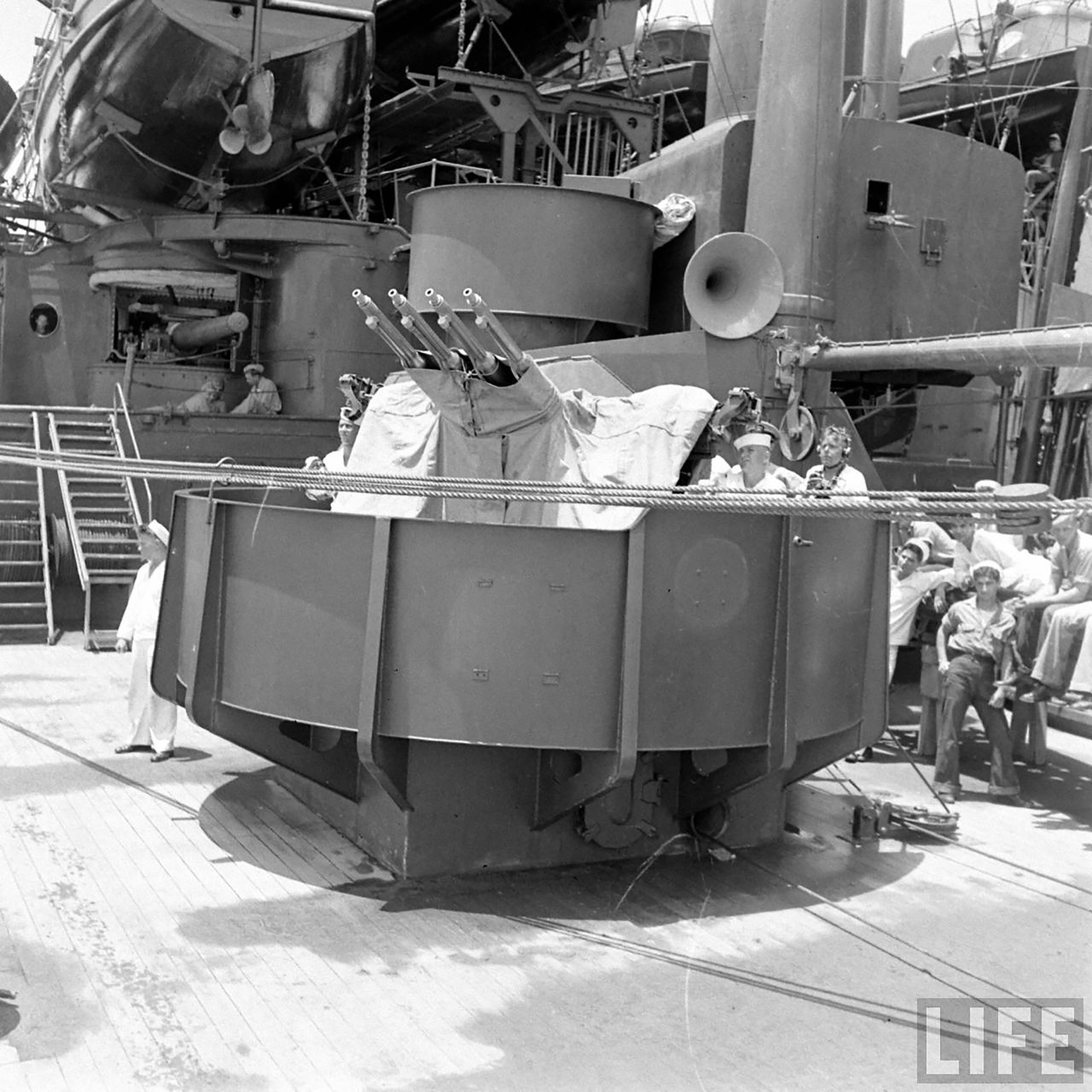
Here is the USS Oklahoma’s plan section, (in white), overlaid alongside the 1.1" mount on USS Arizona 1941 plans:

(For those interested…in “flogging …”)
To clarify, Some may believe the Arizona plans show the support base for the 1.1" gun tub as round.
The USS Arizona plans that I have, do show a round “base” but this is the “mount interface for the 1.1” gun". It is not the base for the gun tub platform. The square base is shown on the USS Oklahoma plans.
Here is a link for the Oklahoma’s plan showing dotted lines under a similar Gun tub. It indicates a square base for the gun tub and a round base for the actual gun mount.
http://www.researcheratlarge.com/Ships/BB37/BOGP/RG19AlphaOklahoma157370-3_a.jpg
Tracy White discussed the base of the Gun tub on another forum. He had written that they are “round on Arizona’s plans”, but was unsure if that was the support underneath the platform or the “mount interface” for the 1.1" guns. ( The circular lines were solid, not dotted)
He reviewed further evidence, (Including a photo of USS Maryland), and posted his current conclusion of a square base. Also, another posting on that same Forum stated the 1.1" gun director platform was mounted on a “pipe” of 9-12" diameter. This conclusion was based a photo of USS Pennsylvania:
Link: http://www.shipmodels.info/mws_forum/viewtopic.php?f=47&t=12942&start=1860
Another member interperted the plans to indicate a 22" diameter pole to support the gun director platform.
Somethung extra…
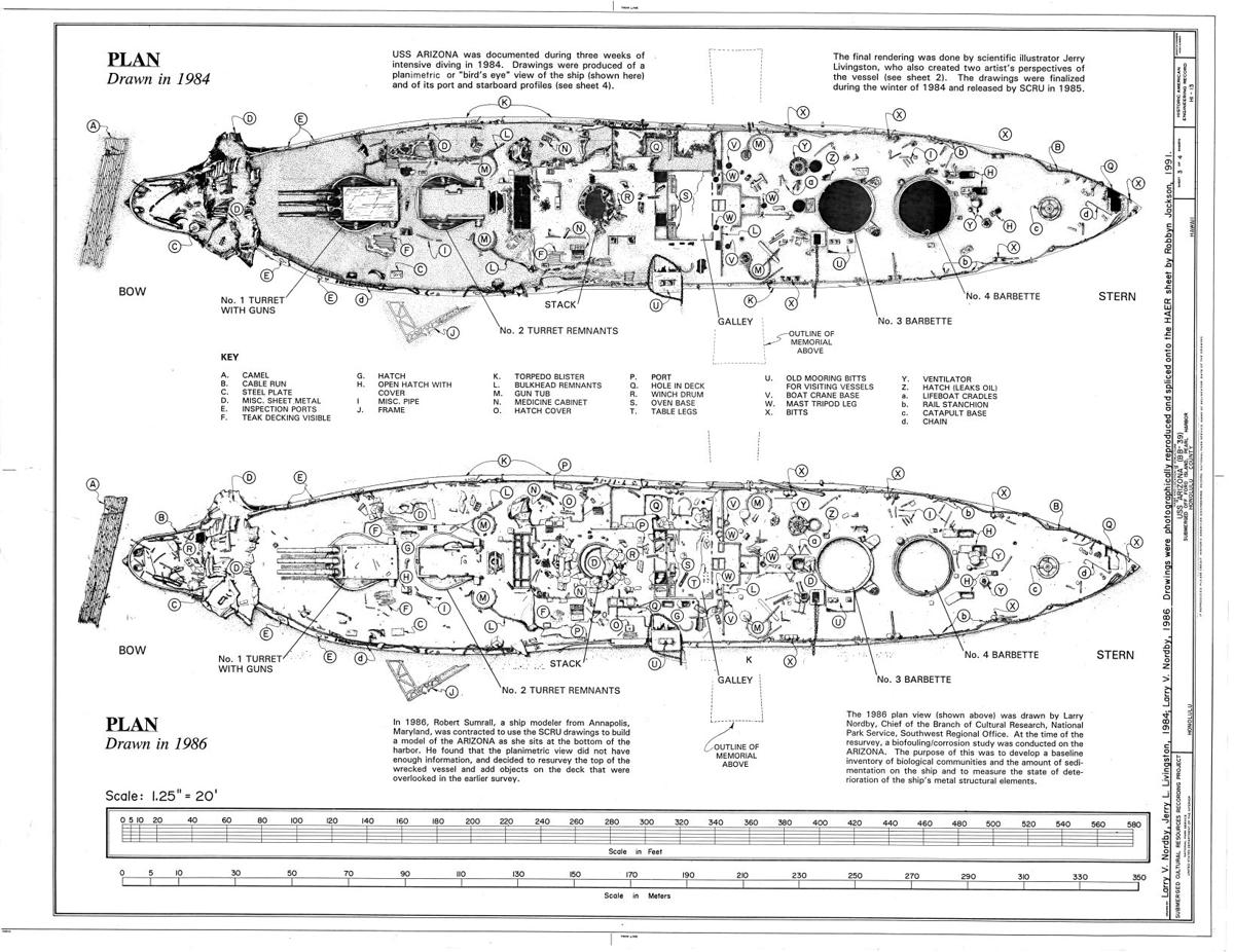
I did not recall these two Drawings being posted here before.
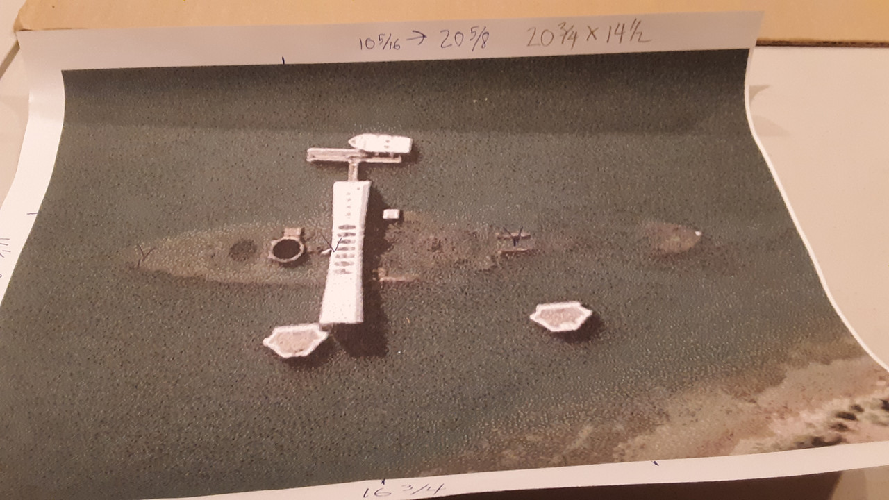
Arizona “submerged” :

Alt link for image: https://bloximages.chicago2.vip.townnews.com/tucson.com/content/tncms/assets/v3/editorial/8/ac/8acd8a1c-ac2b-11e6-830a-0bc5709966ce/582ca71966c76.image.jpg?resize=1200%2C926
.
For a better perspective of this photo…

Nino
At the risk of sounding callous, and that some of my work is reflected in those drawings, the NPS drawings are started on a blank sheet of paper, so to speak. This means that if someone mis-measures, then it gets draw in, still incorrect. Some of these measurement were done under real poor visibility conditions whic caused some errors. For examples, on 1984 drawing (the upper one), on the port side of barbette 4 there is a hatch laid out at an angle. That was because the diver measured off the gunnel, but did not realize that the deck edge is ‘scalloped’ there. so they drew his data in incorrect. Also, on both drawings turret 2 gunhouse sides have chunks ‘missing’. In actuality they don’t. and any picture postcard photo of the ship will show that.
What this all says is that despite drawings noted as ‘official’, they may not be accurate. One must use a variety of source material and gleen what you can, with an open mind.
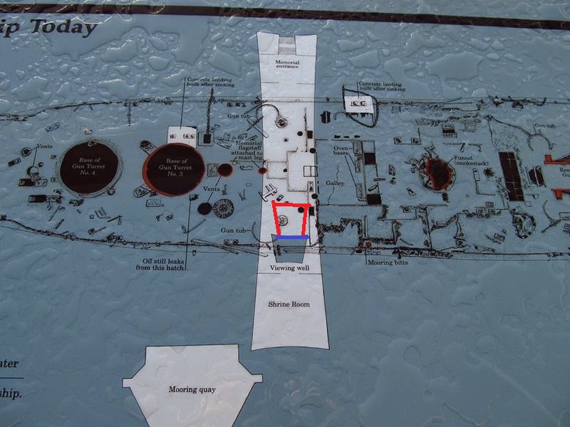
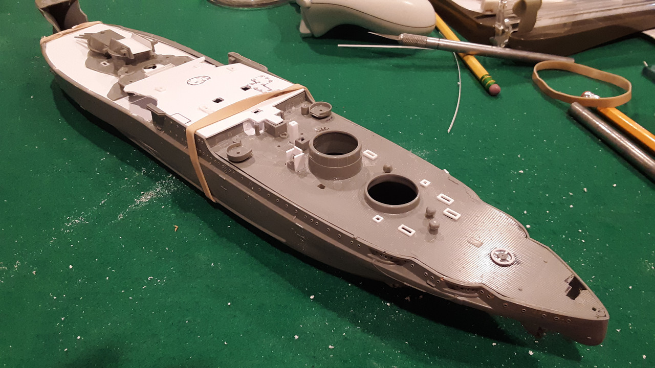
Working on the hull and getting ready to glue decks on. Also I’ll post a photo of the drawing on the memorial that shows the correct position of the viewing well and where HooYah’s photo was taken.
I purchased some 1/2 MDF and will be starting the base of the diorama.
Here are reduced-size scans of two of the architectual builder’s plans of the Arizona Memorial including the mooring quays drawn by Naval Facilities Engineering Command (NFEC) at Makalapa, Hawaii, recorded 30 August 1977. The drawings may be helpful to you.
Larger scans of these drawings and other NFEC drawings were used to create the Model Monkey 3D-printed Arizona Memorial and mooring quays.
The plans show the correct location of the viewing well, the correct shape of the quays, and their relative position to the wreck, the Memorial and each other. The viewing well position in the 3D-printed Arizona Memorial model matches the position as recorded in the official Navy blueprints.
Hope this helps!
Thanks Steve, you don’t how much this helps. I will be working on memorial soon and your Model Monkey’s moorings!
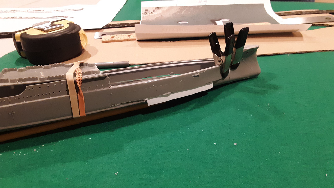
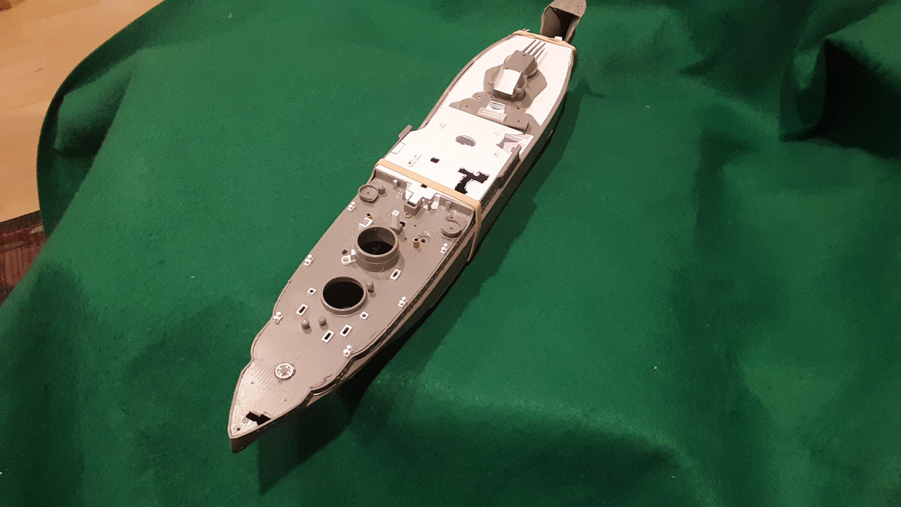
Making a little progress on the USS Arizona.
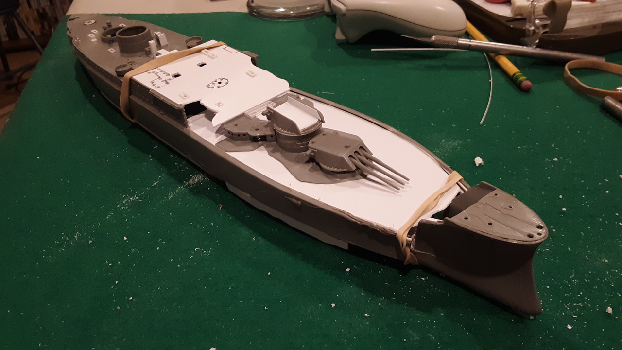
Working on the details of the aft deck and put a coat of paint on the Memorial!

Still adding details…
Amazing research and detail!
I wasn’t able to go to the memorial when I went to Pearl Harbor a few years back, but I was able to see it from the deck of the Missouri.
I needed to make larger bollards for the Arizona. I had planned to cast duplicates from a scratch built bollard, but I decided to just build them assemble line style.
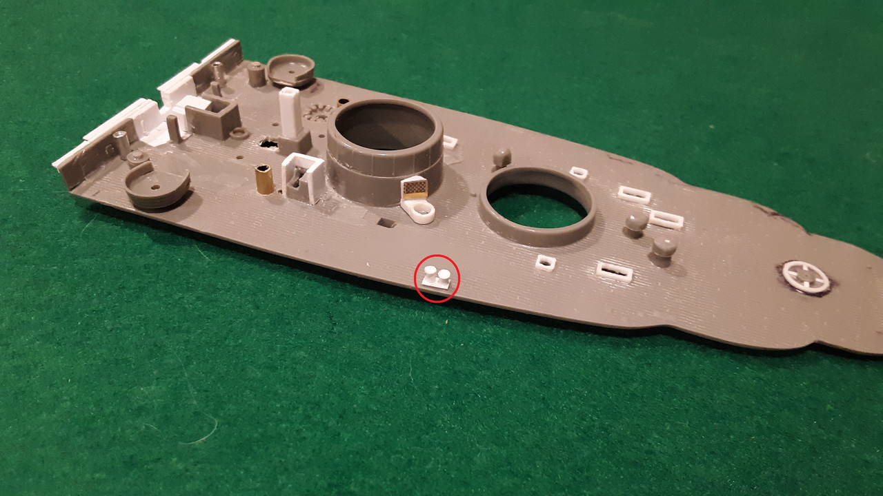
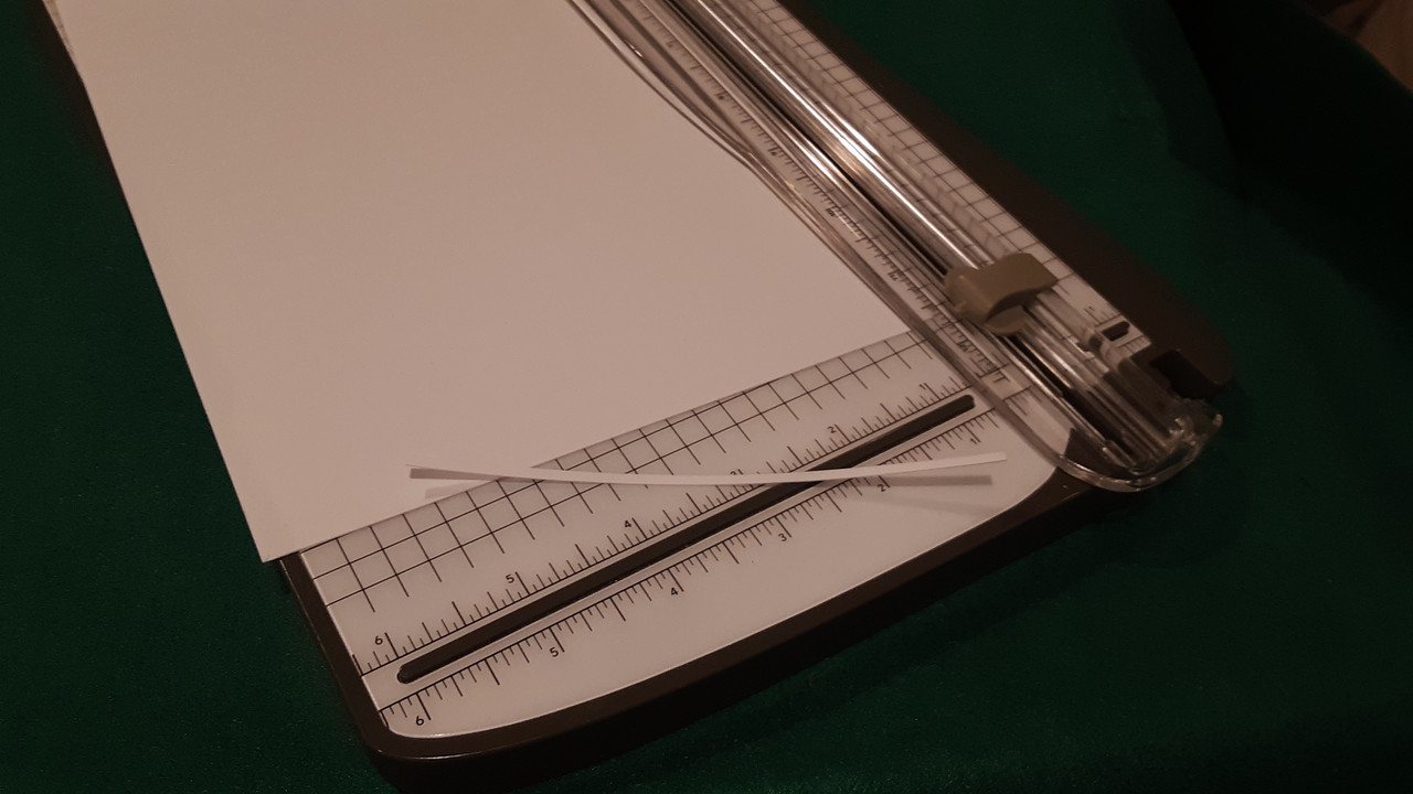
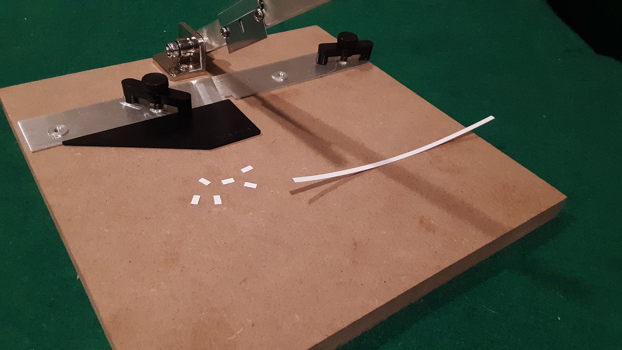

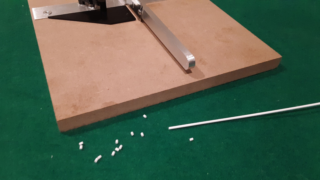
Now I just need to glue them together.
I got the bollards done on the aft deck.
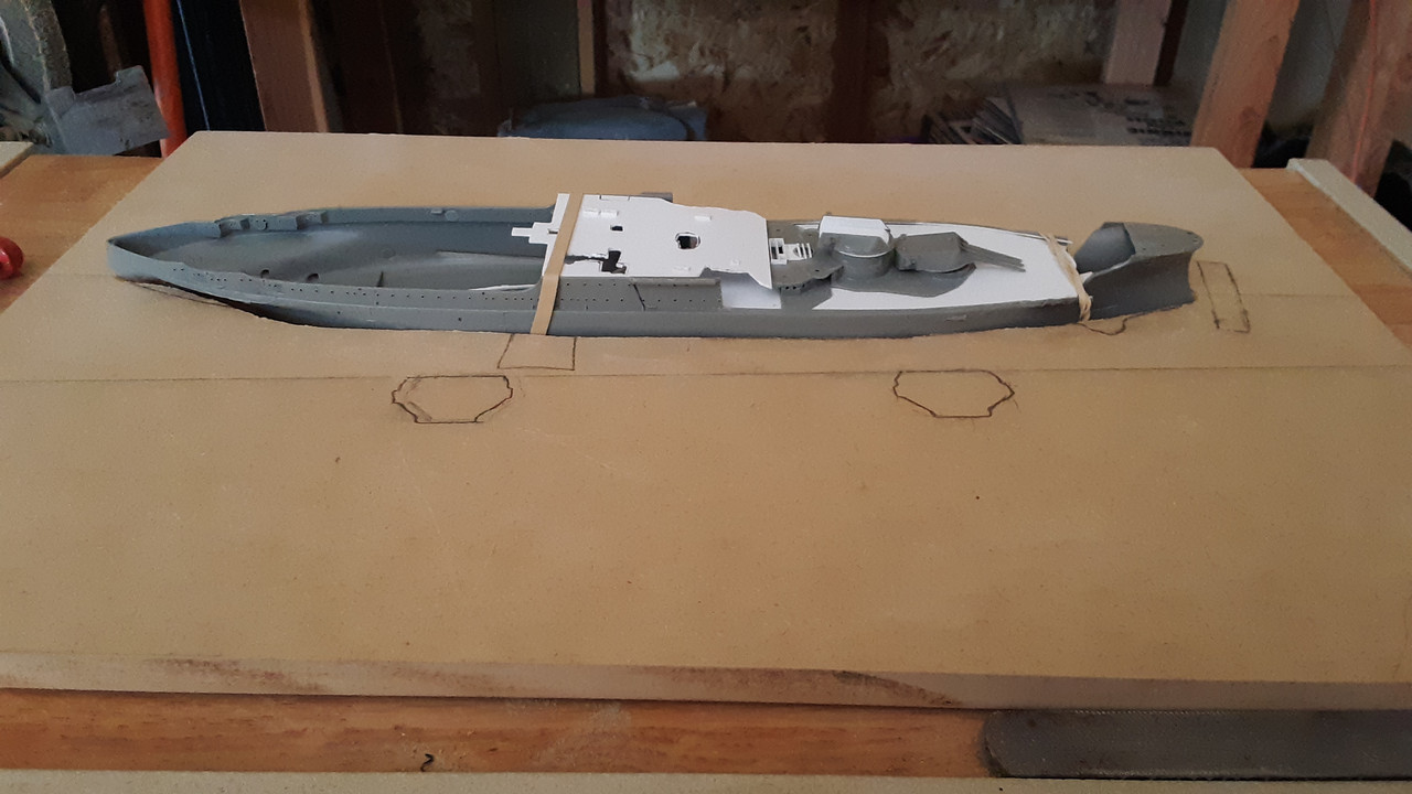
Working on the base.
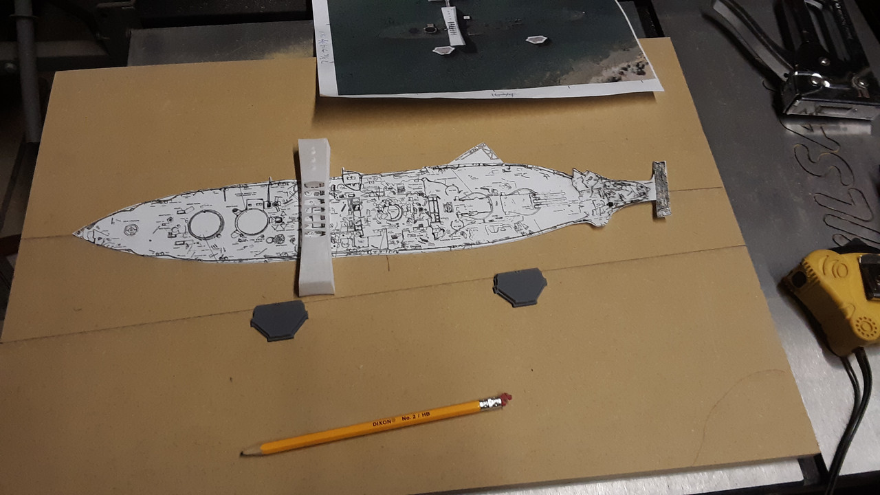
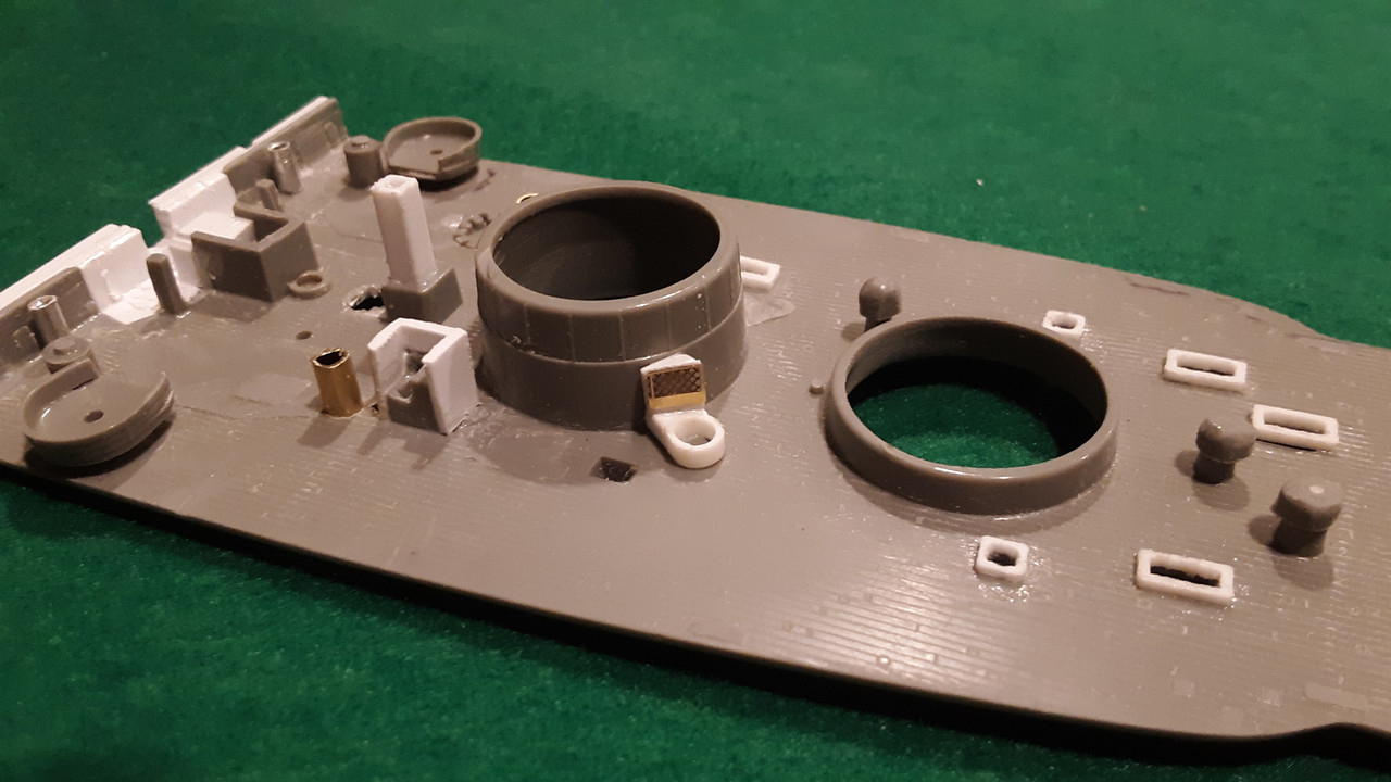
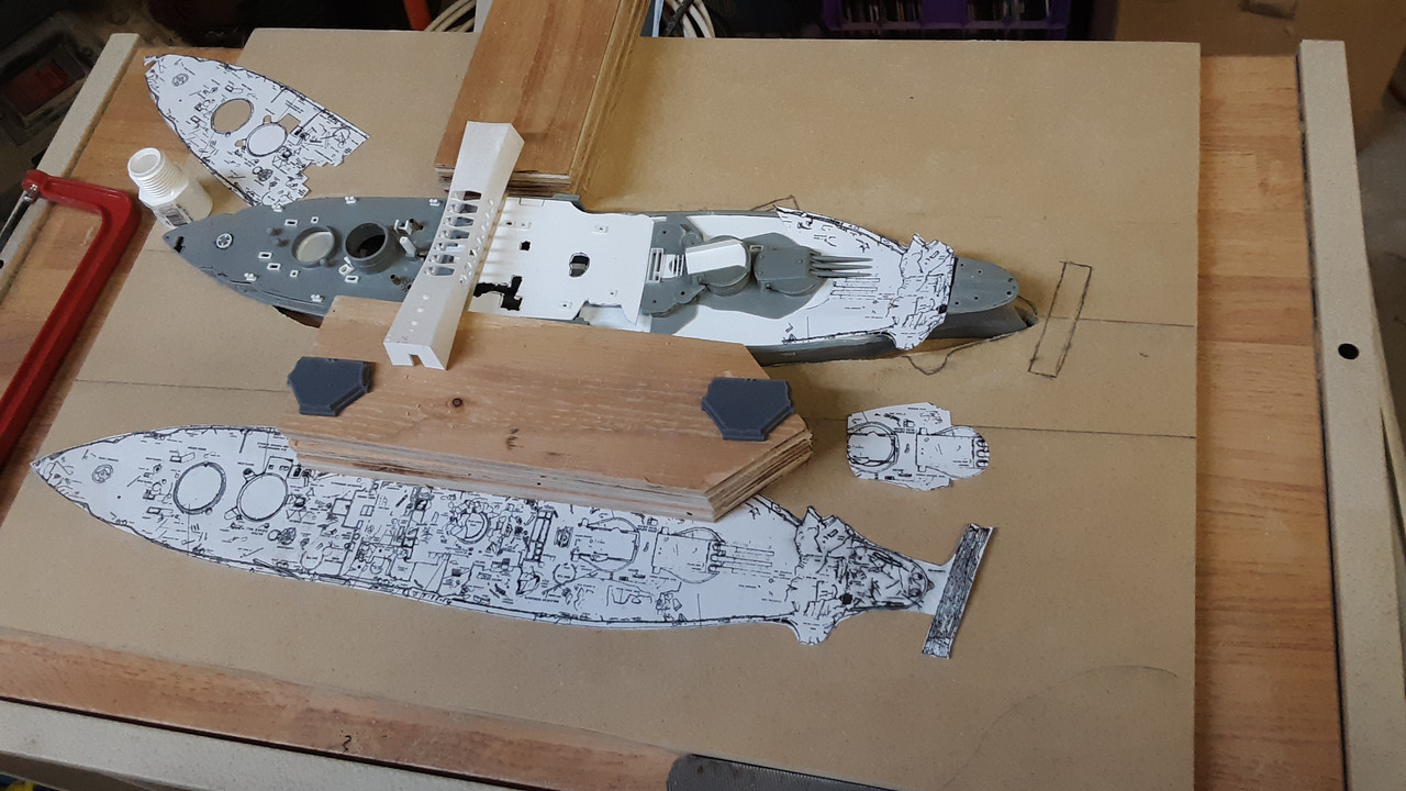
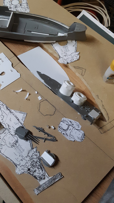
I started working the Arizona again,
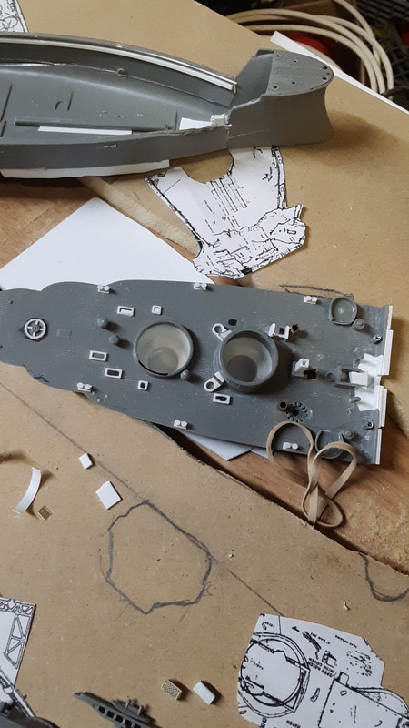
Cut the base to fit the model and did a rough water depth, also I modified some PVC fittings to add detail to the turret ‘holes’
Thats coming along nicely. I like what you are doing.
Glad to see you back at it, this is an amazing project.
BK
Hey You!
It’s nice to see someone doing it like I do! Your project is coming along nicely!
Thanks everyone for the kind words and shown interest, I will post more updates
nice to see you back on this , looking forward to the rest .