Amazing work! Just amazing!
Toshi
Amazing work! Just amazing!
Toshi
Britt, you may not care, but the engine you have is different from the R-1830’s in F4F-3’s and -4’s, which have prominent distributors on the upper front. Vector does make that version, here’s a link to one at Sprue Bros.
http://store.spruebrothers.com/product_p/vec48007.htm
Wright or wrong, the one you’ve built sure looks good!
Outstanding!..especially that Pratt and Whitney. I must get that app too,
Outstanding work! I built the dash 4 last year as Jimmy Thach’s a/c, but it was pretty much out of the box, except for the Eduard cockpit PE. This is just beautiful.
Thanks guys. I’m actually getting more and more excited about this build. Once I get passed the gearbay and wings, the rest ought to be a breeze. John T, I actually plan on building Jimmy Thach’s Wildcat as a detailed aircraft when I get around to it. I’ve been creeping on EBay for a while now. lol =]
John, about the engine…I’m actually glad you brought that up. I take my time researching builds and since obviously I’ve never worked on or flew any of these aircraft, there’s still something that’s going to escape my attention. So with regard to the R-1830, I took my time looking through everything that’s out there and I came up with a lot of references that didn’t help me decide which engine belonged to the -3.
I’ve seen the one below stated as being used in Wildcats, but I haven’t seen any other designation with it.
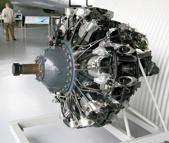 Untitled by Britt Vallot, on Flickr
And then I’ve seen this one as well with the -86 designation.
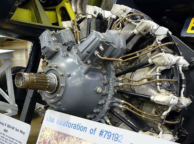 e77be2d947cdfe3c4f66b4877d14aa74 by Britt Vallot, on Flickr
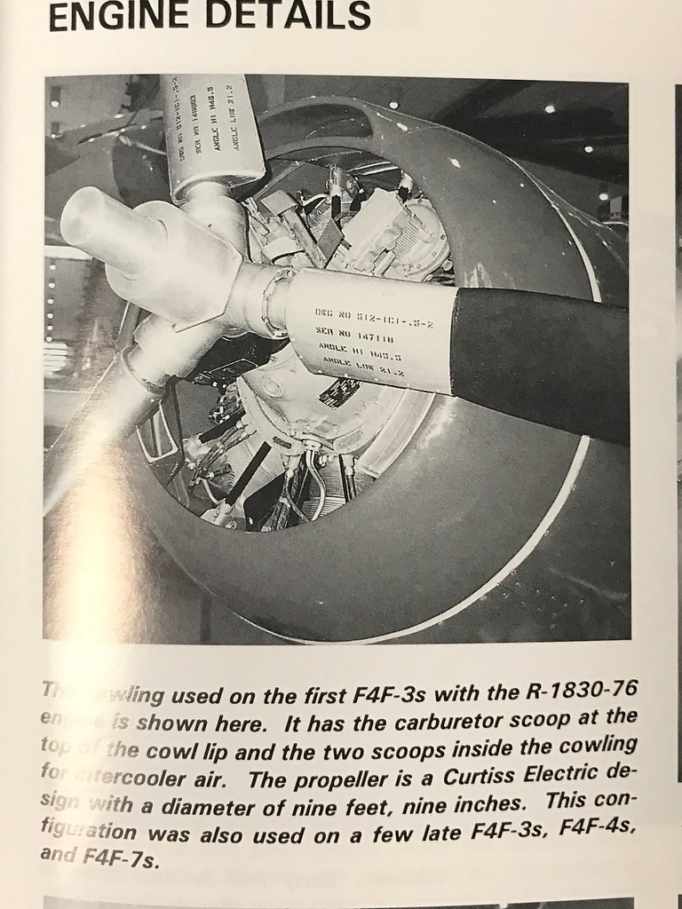
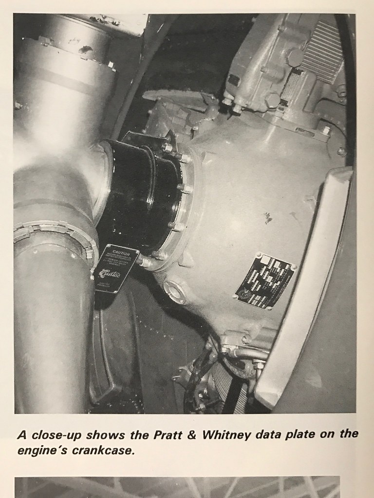
What I settled for was based on a Squadron/Signal Wildcat in detail book I picked up a while back where they discuss all the data on the Wildcat. They have the -3 listed as using the R-1830-76 and -86 and -3As with the R-1830-90. These are the pics from the book:
 Untitled by Britt Vallot, on Flickr
 Untitled by Britt Vallot, on Flickr
They include the two large Distributors as seen on the kit part. So I felt that was the safest route. Also, thanks for the help with the name. Before now I hadn’t actually had the proper name for that particular part. I understood it’s general function with the electrical component of running the engine, but now I understand it a little better with having the name.
So have I missed something? I do enjoy accuracy in building these scale aircraft and I’m always happy to have the help and experience of those who know it better.
John, I think I may have misunderstood what you were getting at. I first pulled up that link on my phone and figured it for the other model they make (being the first picture I included in the last post), but after looking at it a second time it appears to be the model that I purchased…which is the Vector 48007.
I feel like I missed something.
Britt, I think you have the right engine after all and I did not look far enough down in your photos. Sorry for the confusion.
That engine looks like it’s ready to start up
No worries John. =] But you did have me worried there for a moment. The way I figure it, I’m a young man in this game. At 35 years old, I’ve still got plenty to pick up on in the way of what was used, where it was used, how it operated, and how it might’ve varied in a changing wartime environment. So no sweat. I’m always happy to learn something new.
=]
And thanks silentbob33. When I’m done with her, she’ll be able to fly at least once! =P
I want a video of your firing up that engine!!
Incredibly detailed and painted. As others have said, it does look like a real engline. Many kudos for a great job on that power plant. [t$t]
Your unique style falls into another genre of modeling, pro modeling. I’m astounded!
Toshi
Thanks Toshi. I am aspiring to do so. =] It seems there’s always that one hang up that keeps me from pulling off exactly what I aim to put together, but I suppose that’s what keeps me coming back, right.
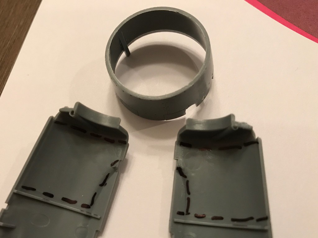
Progress is slow, but she’s coming along. Lately, I’ve had just enough time to sort out one component and size up how it’s going to fit. Here’s where I’m at…
 Untitled by Britt Vallot, on Flickr
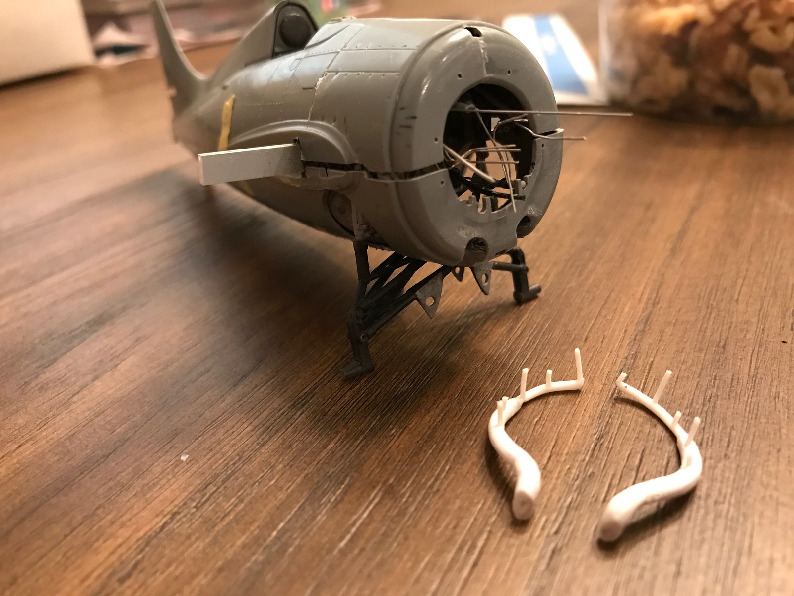
I plan on thinning out these marked off areas with a dremel so that they will bend a little more easily when I’m poking at them. I’ve noticed how the panels on Wildcats would bow out along forward top of the wing root. In the past, I’ve tried my hand at doing this by carving away at the surface, but I’ve never been able to sand it back down appropriately. So, I’ve come up with this idea to leave the surface relatively pretty and scrape free while still putting in whatever warping I see fit to include. More to come on how this worked out. I also removed the forward part of the cowl that included the carb scoop since this series of Wildcat didn’t have one. The JPS conversion set has included the proper replacement. =]
 Untitled by Britt Vallot, on Flickr
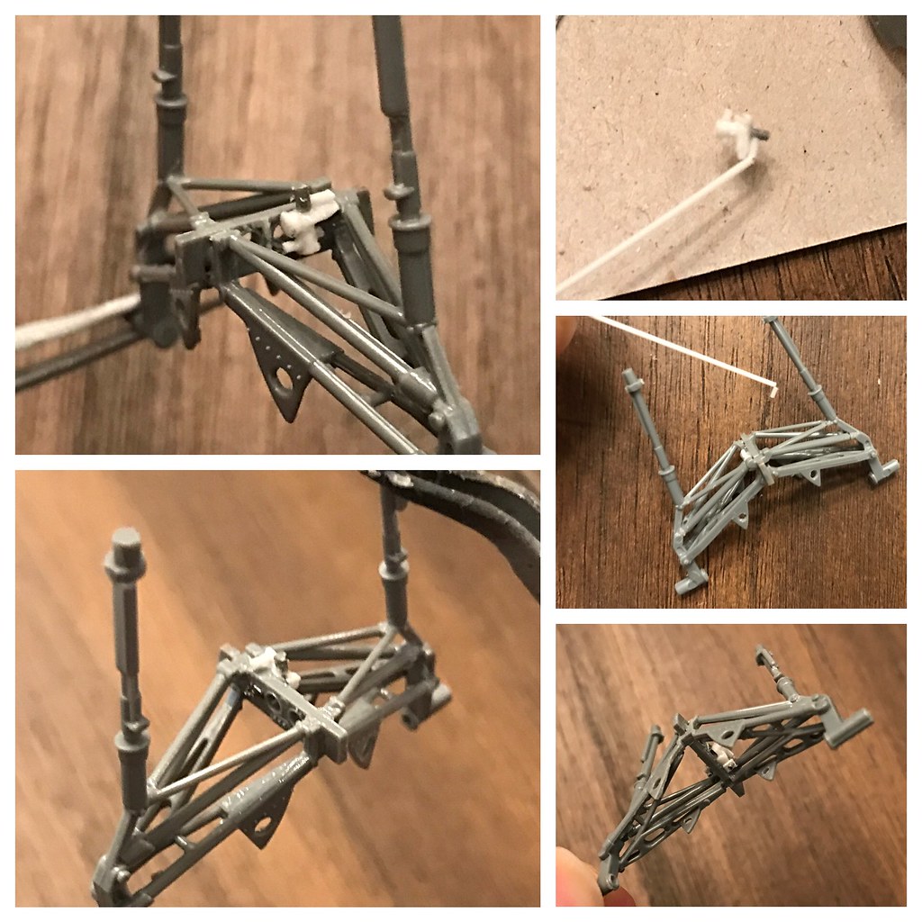
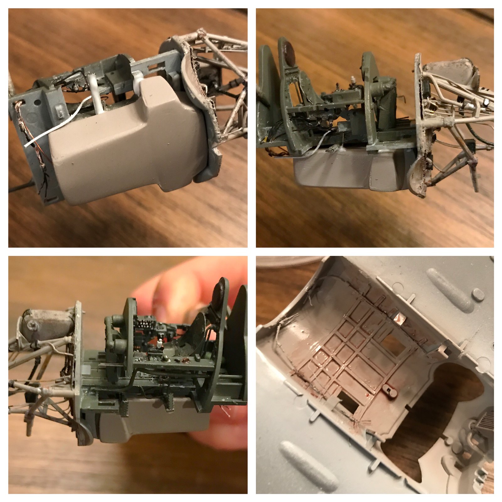
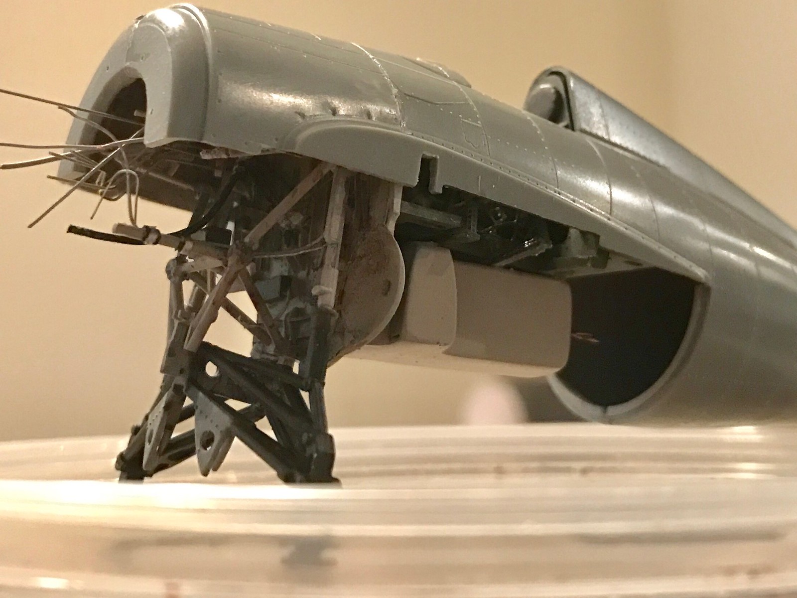
I went ahead and built the landing gear now so I could paint everything together. I corrected the fuel pump found on the center drag link supporting the landing gear. The detail looks a little soft right now with the light glaring off of the white styrene, but after a coat of paint and some weathering, this will work a whole lot better. A hose will come straight from out behind the firewall where the fuel tank is stored and will fit onto this later. I also added some PE fittings that will run the brake lines through this area. I think I will just get all of everything attached now with the gear bay and mask it for painting the fuselage. I don’t want to try getting in there late in the game when it’s dark and closed up and break something down the road. Some very minor modification was done here and there to various bushings and joints to add a bit more life where it was lacking.
 Untitled by Britt Vallot, on Flickr
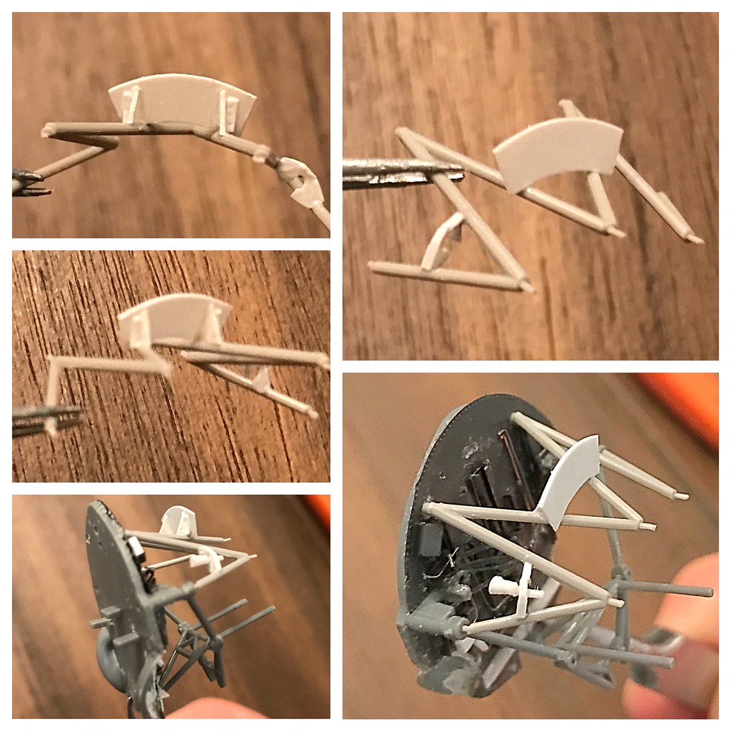
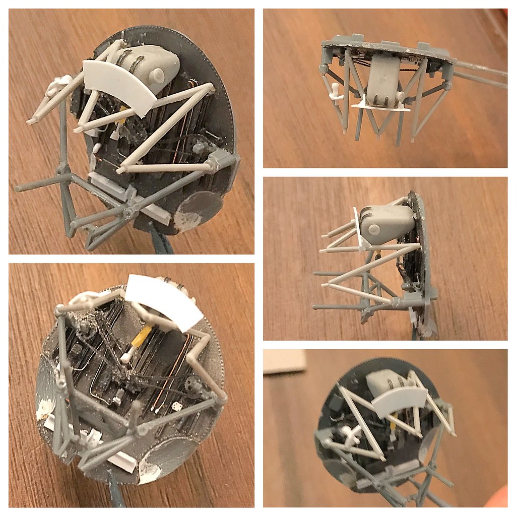
Here I built up the armor plating in front of the oil tank and have it attached to the engine mount as well as a mount for a conduit that ran some of the engine’s electrical needs.
 Untitled by Britt Vallot, on Flickr
This is how it’s going to fit up with the rest of the firewall.
 Untitled by Britt Vallot, on Flickr
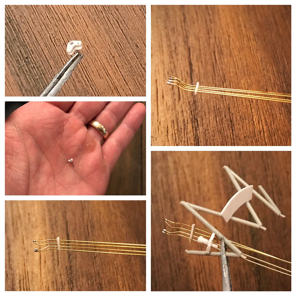
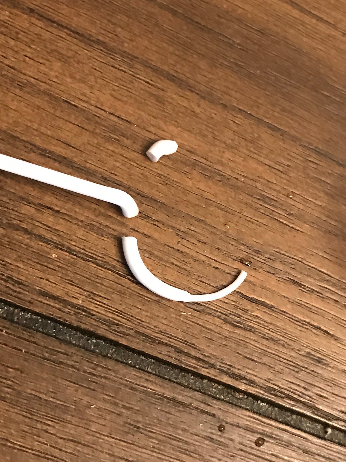
The rest of the plumbing with the harness to help with the mounting of all this. The part in the top right frame is the linkage for what is the throttle I believe. I’ve been getting in the habit of making things easier for myself by leaving a little something to work with like the extra bit of length from the stretched styrene you see. Instead of clipping this part off immediately, I can use the length to grab it with a pair of tweezers to help with fitting where it goes and priming/painting and so forth. Just some piece of mind for those who need it. =] Consequently, following the snapping of that picture…this part shot out from my tweezers and landed behind me without making a sound. Searched for about 5 minutes and gave up. I got lucky when I began picking all this up and found it on the floor. Took one more picture just to show you how tiny it is…from the safety of my hand. =P
That’s about how this section is going to break down. Just a few odds and ends to attach in the way of hoses and wiring. Then, prime and paint!
Aaaaand finally! Paint!
I’m happy to get this section wrapped up. There are just a couple of knick knacks to tie up in some later steps, but this is pretty much it here. Next will be the engine ring, intercoolers, and matching up the engine to kit fuselage…then hooking up all those damn wires and hoses! =]
Here’s where I’m at.
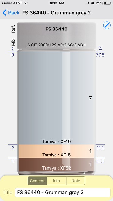
I made my own Grumman Grey based off of FS36440. After reading around, I’ve found this to be a close place to start. Here’s how I mixed it up.
 Untitled by Britt Vallot, on Flickr
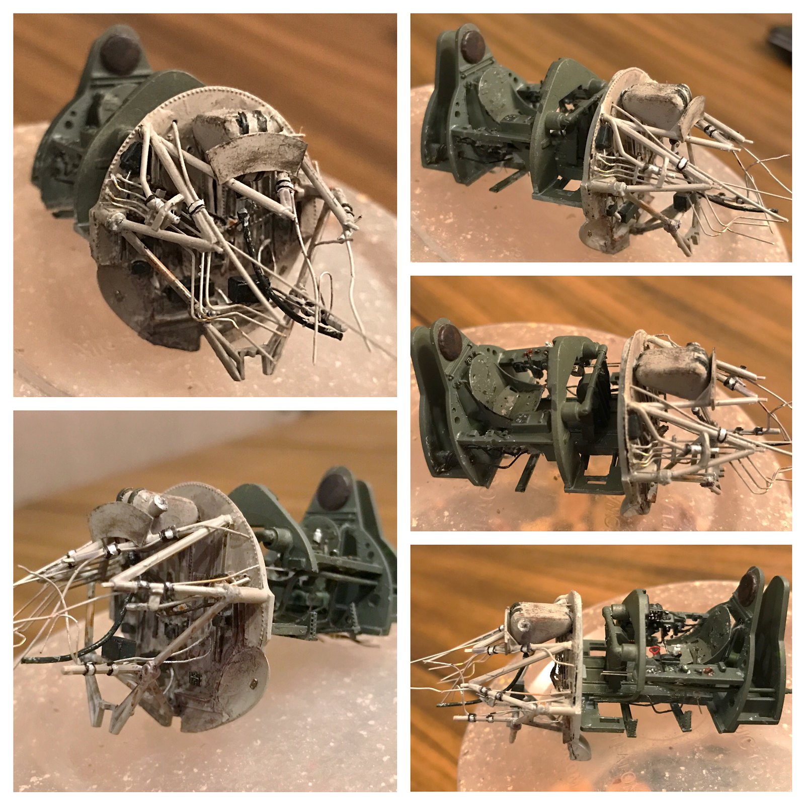
Here’s everything dressed up.
 Untitled by Britt Vallot, on Flickr
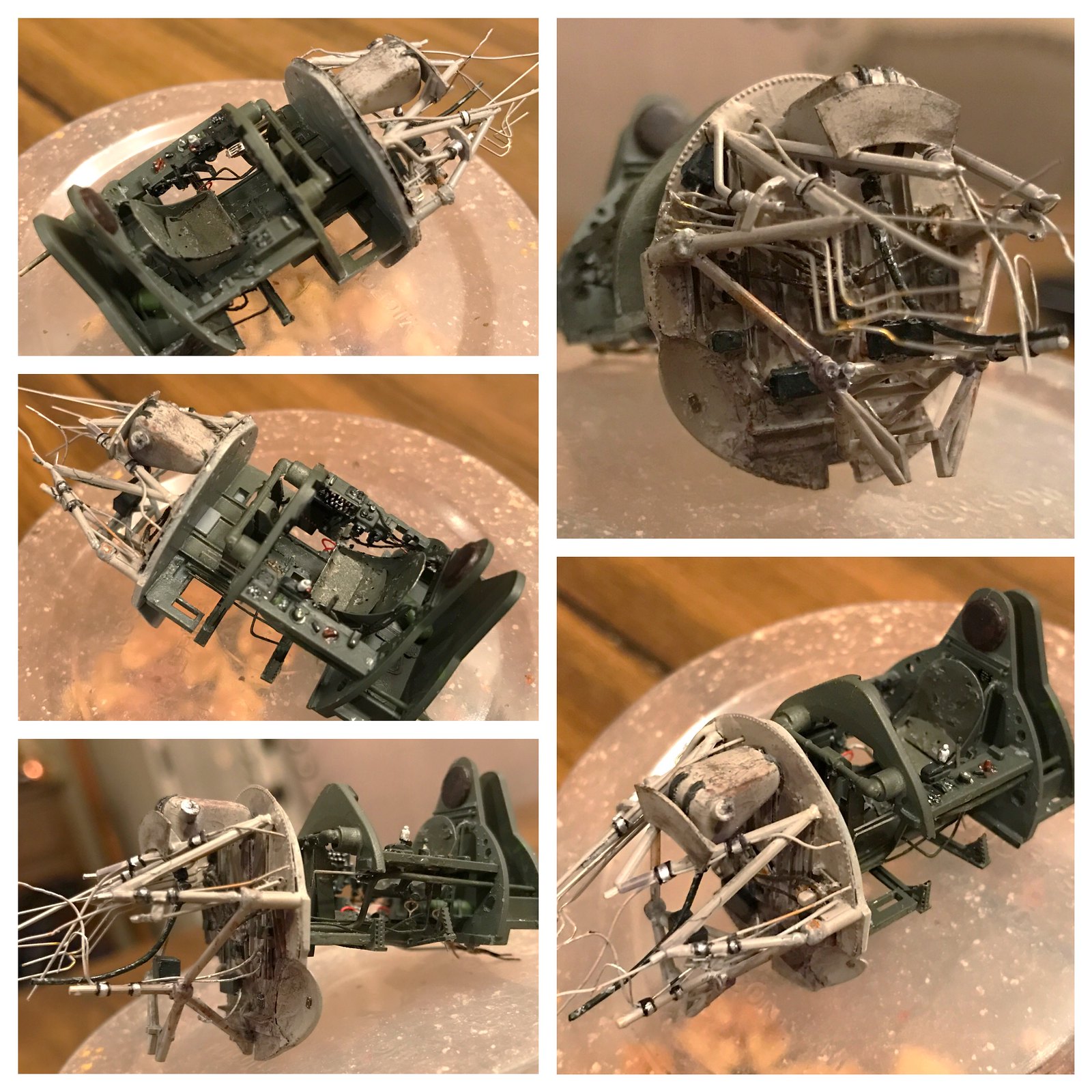
This is the actual color of the Bronze Green I mixed. Without brightening the photos, it shows a truer color. The Eduard PE has placards for this area. You may notice the “Grumman” nameplate behind the seat and the Dataplate on the bottom of the firewall. Nice additions.
 Untitled by Britt Vallot, on Flickr
 Untitled by Britt Vallot, on Flickr
Here’s the fuel tank fixed to the bottom of the cockpit floor…the glue is even still wet =P
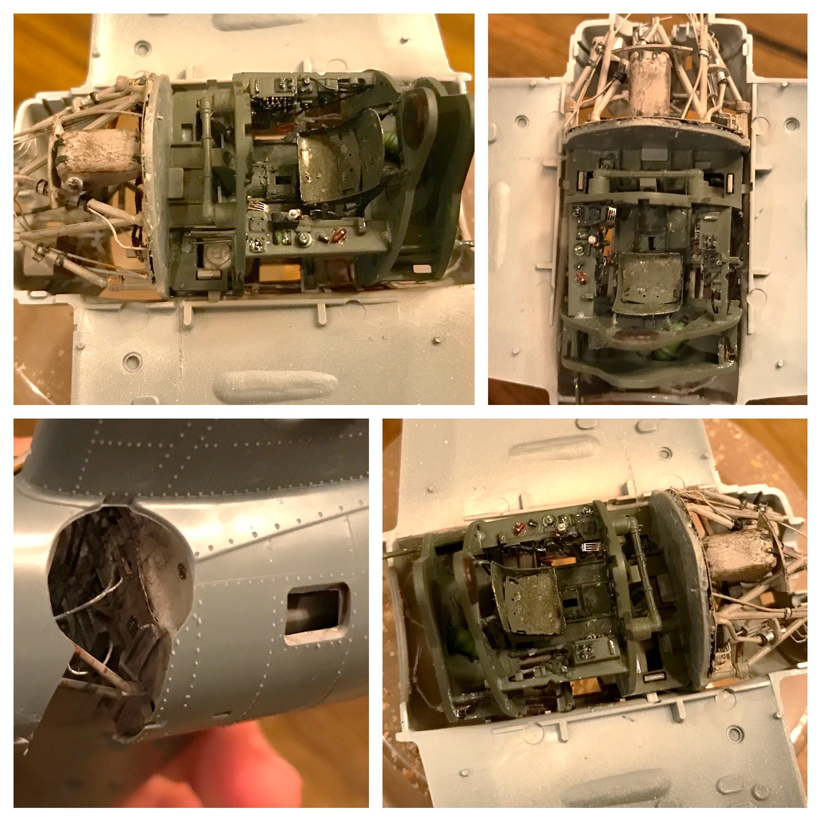 Untitled by Britt Vallot, on Flickr
And here’s how it all fits into the fuselage. I’m actually quite happy with how all this turned out. I wasn’t 100% convinced I’d get everything right on the first go around.
Firewall and Cockpit - done.
Impressive, Britt!
That work looks SOOO good and that engine…WOW !!! This is amazing stuff.
BK
Thanks guys. The fun part is about to come next with getting these wings on and the engine fitted. Then the PAINT! =]
Wow - very nice ! A lotta detail in that little package.
Chris
Wow…that looks amazing! I had to go and double-check the scale on this
Finally back with enough content to actually have a post. The busiest part of my year is finally coming to a close and life begins to become more enjoyable. Still plenty to do…but definitely more enjoyable.
Cranking out an engine!
 Untitled by Britt Vallot, on Flickr
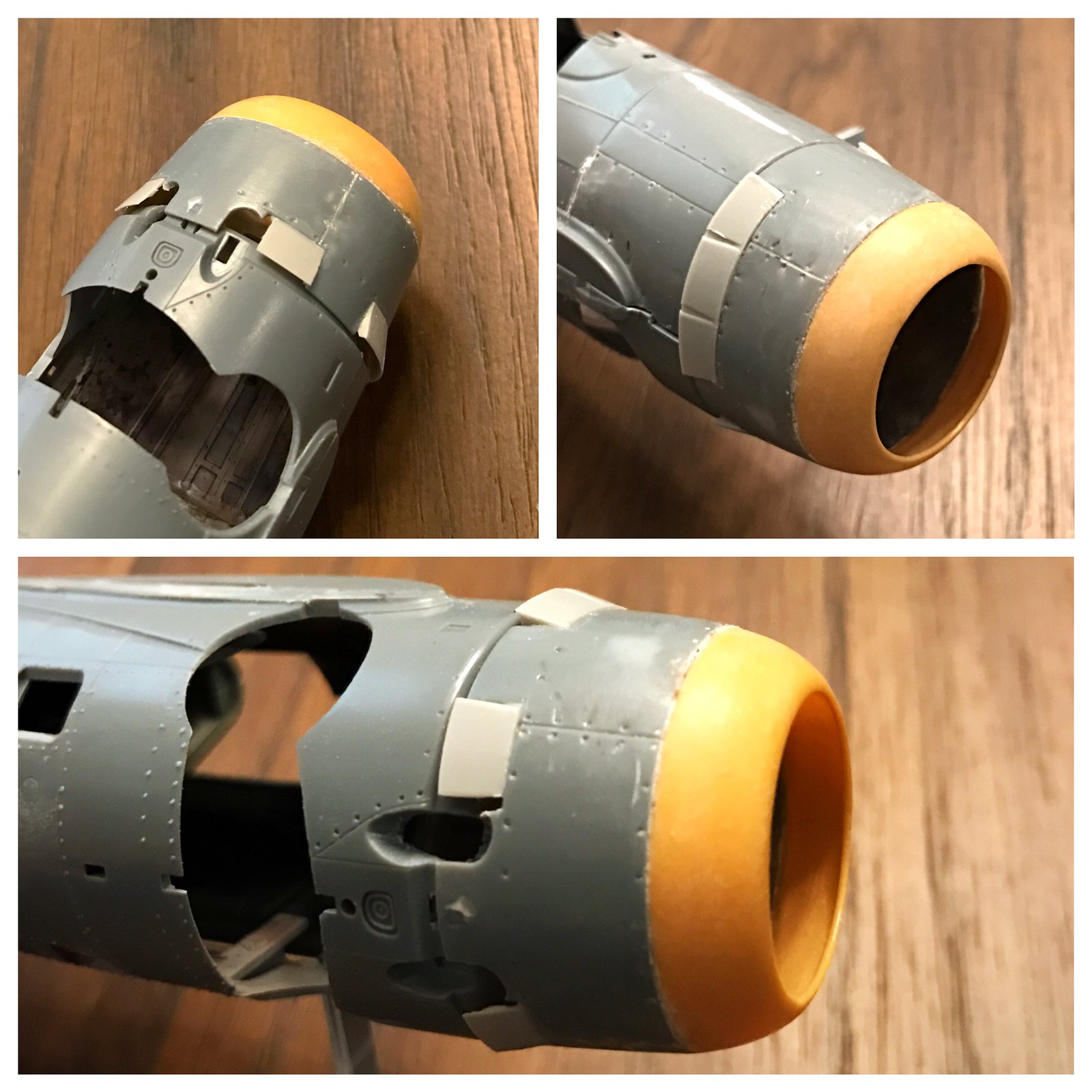
So, I’m finally getting this Wildcat to a point where I can address the Vector Pratt & Whitney engine I’m dropping in. Any time you change the script it usually means the fit is going right out the window without some adjustments. Luckily, for this kit it wasn’t so bad. The JPS replacement cowl ring for the -3 series without a carb scoop goes on like a charm. No real surprises with this part.
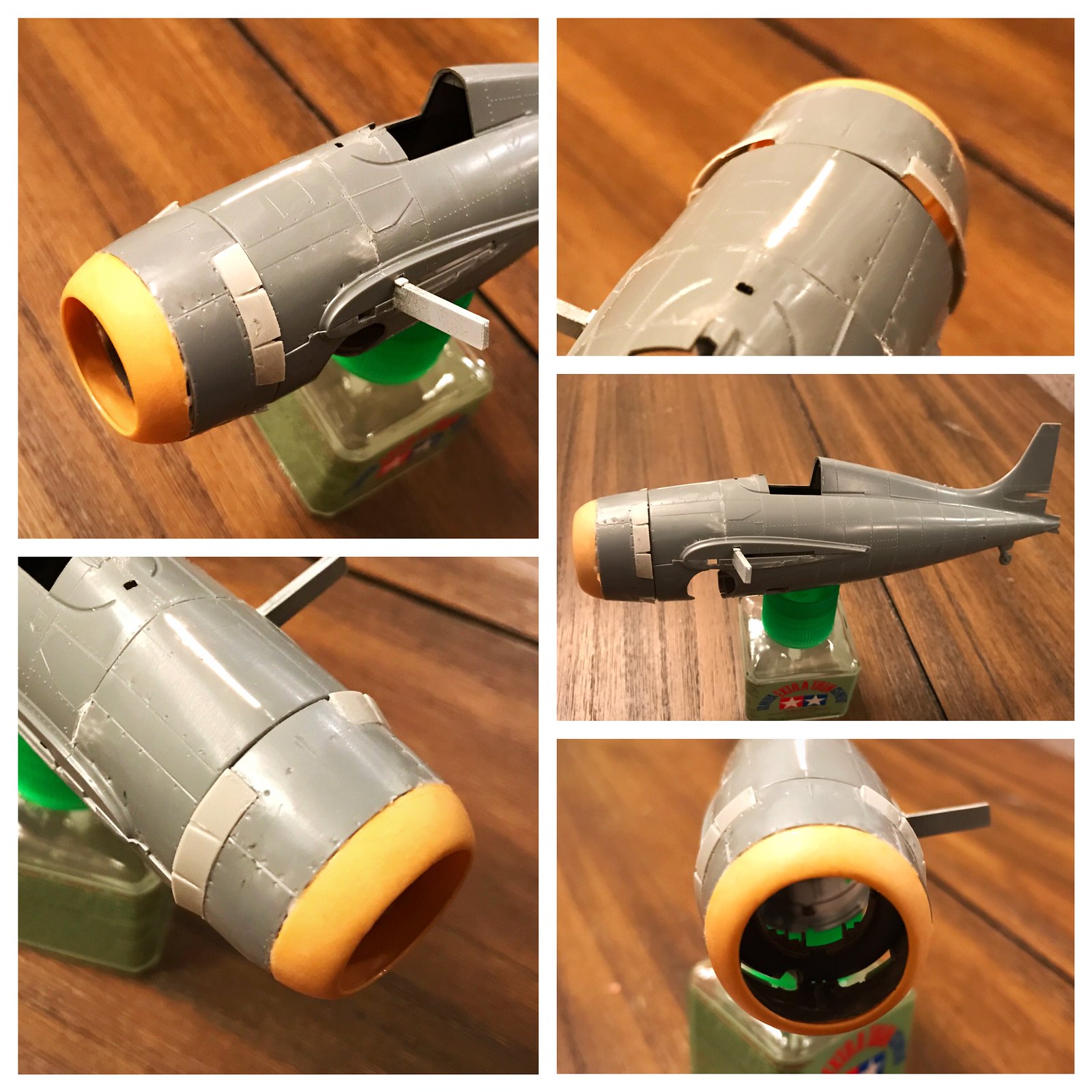 Untitled by Britt Vallot, on Flickr
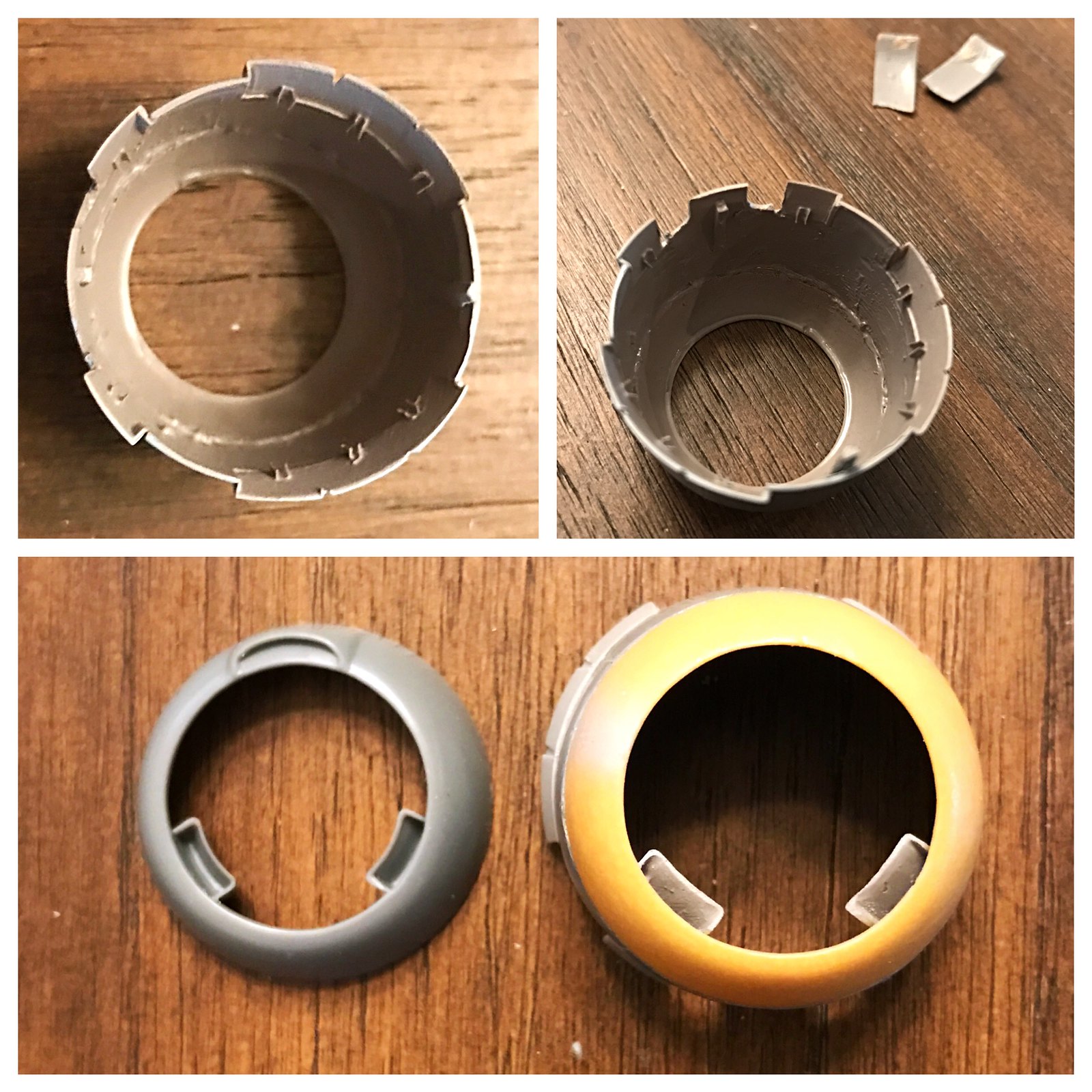
A few touch ups here and there…some CA to fill some gaps…sanded and smoothed…and voila. =] I have sanded the interior of the cowling down very thin so I can make use of “denting” the outside as seen in the warping of these sheets of metal after continous removal and replacement from servicing the engines. This worked out much better versus cutting and sanding on the exterior surface.
 Untitled by Britt Vallot, on Flickr
You can see the lighter colored plastic cowl flaps are from the Hobby Boss kit. I had a small issue with sanding that bit down a little too much and caused me to have to redo them. Since I’m already robbing more than a few parts from this kit, I figured I’d measure it out and give it a shot…wouldn’t you know it’s a pretty good match. =] A little Tamiya ETC and done. I’m glad I did it too because originally I was going to leave the flaps closed, but that would further limit seeing what little of the exhaust was going to be visible anyhow. So it worked out. The interior cowl flaps were addressed with thin brass sheet. I’ll leave it right here for this point as the space for all of this is very tight with the engine just barely squeezing in there. I’ll string up these flaps after the fact once I’ve got the P&W engine secured. The intercooler scoops went on without too much fuss either. I have the original Tamiya kit part side by side with the updated and corrected version for Butch O’Hare’s Wildcat. A definite improvement.
 Untitled by Britt Vallot, on Flickr
Here’s an intermediate shot of what’s going on underneath the gearbay.
 Untitled by Britt Vallot, on Flickr
And a quick assessment of how all of this is coming together.
 Untitled by Britt Vallot, on Flickr
I may have a shape issue with regard to the bottom of the fuel tank. I’ve recently seen some where that this tank slants up to the back of the tank. I suppose I’m fine with what I’ve got for now. It won’t ruin anything about this particular build, but just a little FYI for anybody out there following that ever plans to scratch out this part. =]
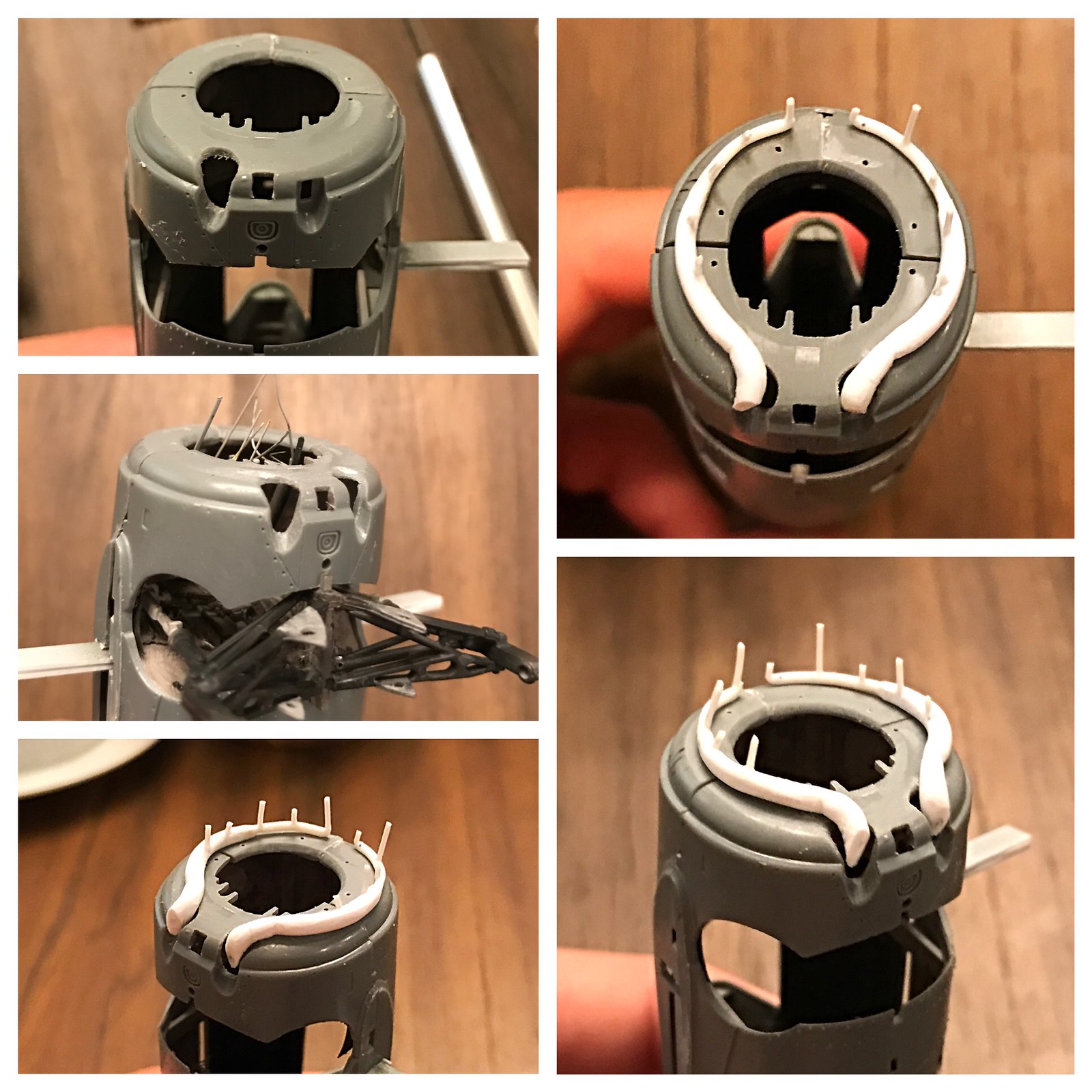
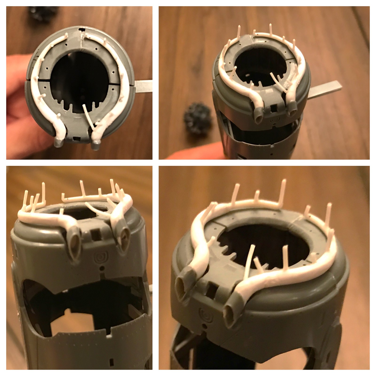
The Exhaust Manifold
A quick step by step process of how I went about this. Last time I did it with brass rod and soldered it all together. This time around I tried to do it all in plastic. I started with a plastic rod that I shaped into a curve using a lighter. This was fitted together into a plastic tube using the same process…very slowly heating the tube so I can get the curve just right without having to over work it. I’ll double check the sizes for these later on. It was all joined together with Tamiya Extra Thin Cement. A couple of intermediate parts were heated and mashed down to give it extra width and were bent with the mashing to provide the last stage before the kit parts Tamiya molds as the exhaust tips. I drilled these out and sanded them thinner to bring them a little closer to scale. A smaller plastic rod makes up the manifold connecting to the engine. A little sanding brings everything looking a little cleaner…a little Milliput makes it all connect together and makes it a happy exhaust manifold. I love this stuff. All it took was just the tiniest bit to smooth around my edges that were a little fussy. None of this was too bad. Took some patience and a lot of double checking to see that everything matches up. Totally worth it!
 Untitled by Britt Vallot, on Flickr
 Untitled by Britt Vallot, on Flickr
 Untitled by Britt Vallot, on Flickr
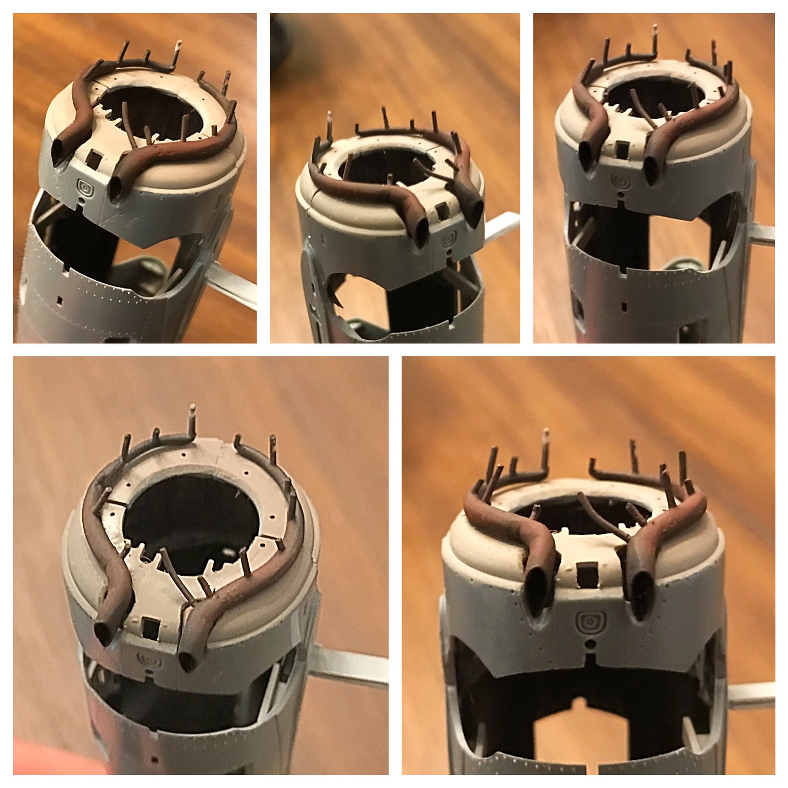
Primed and painted with Alclad’s Exhaust Manifold and some Tamiya NATO Brown to give it a little more character and lighten up the color.
 Untitled by Britt Vallot, on Flickr
Next up, mounting this P&W engine and figuring out where all these hoses and wires go! =]
Thanks for following.
Excellent tips and tricks here. I’ll be using the exhaust tips for sure on my Kingfisher build. This is just a super build you have here.
BK