The first phase of my project is to make a master for casting my warp engines.
Here is a picture of the acrylic sheets before I laminate them together.

This is a picture of a block of acrylic sheets that I have just finished gluing up.

This pic shows the six layers I have laminated together using acetone as the solvent to bond them into a solid block.

This pic shows the finished block laying on top of a drawing that I have had scaled to the correct 1/1000 scale. Can you see the part in there? lol

This pic shows the block clamped into the lathe. I’ll let it sit for a day to let the laminate fully cure.

Let the chips fly! This is the material as the lathe cuts it away from the block.

One more 1/64th off and we’ll be there.

I’ve arrived at the final outside diameter of the part! Now to rough out the shape.

I knew that warp nacelle was in there! LOL
The blue area won’t be part of the final piece.

The finished model will be 9.6457" long and this piece will be about 3-5/8" long.
Note the cooling fin areas are undercut to except styrene rod stock.
That is why the profile might look a bit too thin right now.

All done I just need to seperate the part. I have also scribed guide lines for the main cooling radiators.
See the family resemblance? Rod stock will be used to add cooling fins.[:p]
Maybe I’ll cast up five warp nacelles and make a Baton Rouge based dreadnaught. What would I call it? Hmmmm…How about the Mardi’gras Class? LOL
You may have noticed that this nacelle lacks a Bussard collector.
There is a reason for that.[;)]
I will be turning one the correct size for a possible resin kit (don’t ask, LOL) and one slightly under size to use as a form to thermo-form domes for my build. Here is the waste from the nacelle that will yeild these parts.
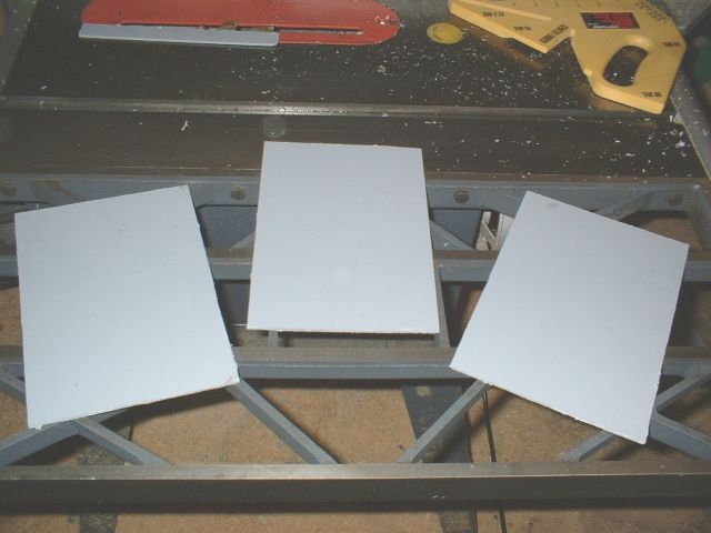
The second step is to build a castable saucer section out of 1/8th inch thick styrene sheet.
I’m lucky enough to be able to glean scrap styrene from work. I used my tablesaw to cut away the edges of what otherwise would have become a shutter.
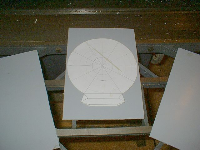
I have prepared a corrected drawing to use as a templet.
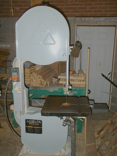
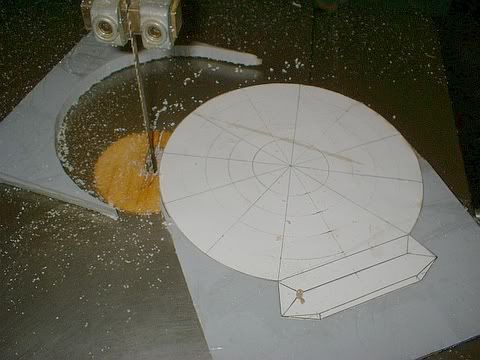
Time to put this bad boy to work. With it’s 105" blade and 1hp motor, it cuts thick styrene sheet like butter! Yes I still have all my fingers.[:D]
I have stacked the three sheets together and placed the template on top. I then tightly wrapped them together with clear packaging tape.
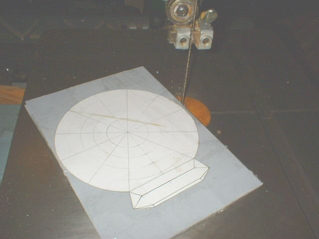
As I cut away a portion of waste I retape that section so the stack stays tight and the template doesn’t slip.
Free at last. I now have the basic shape for my saucer and impulse drive.
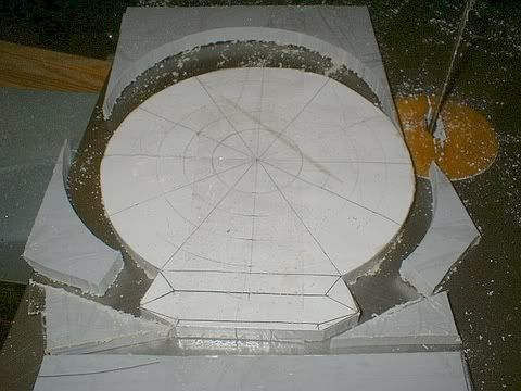
Here are the parts after I have removed the tape and template.
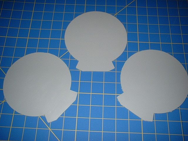
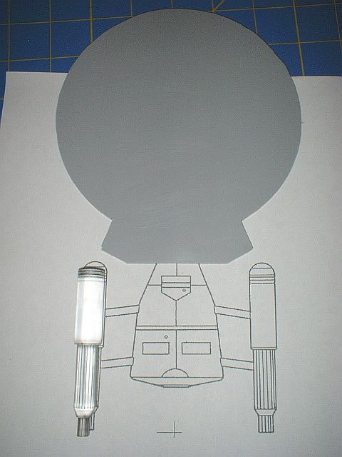
Checking the proportions to my scale drawing.
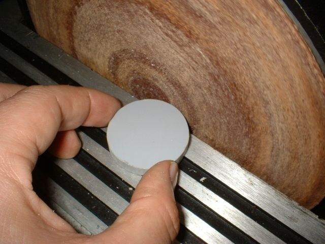
The disc sander is another useful scratchbuilding tool. The area close to the middle of the disc is slower so the plastic stays cooler. This is the bridge section by the way.
Time to do a little scribing. These are some of my favorite tools for scribing.
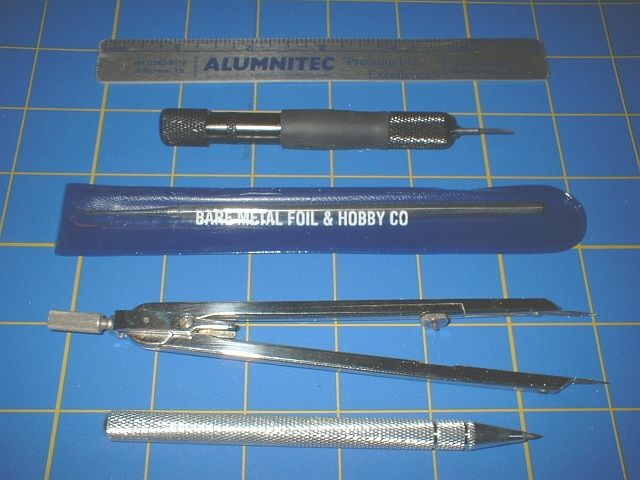
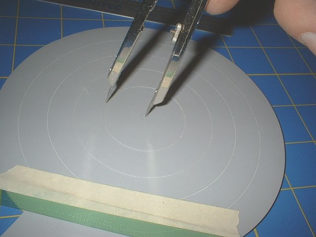
Drafting dividers make dandy circle scribing tools.
This is my favorite tool for crisp straight lines. It is a chisel bit chucked into a pinvise. Note the rubber grip. It’s from a disposable ballpoint pen. I alway steal the rubber grips off these pens for my modeling tools and then throw the pen body in my scratchbuilding parts box.

I use this tool by dragging the tool in reverse. The tool can be turned around and the sharp edge can be pushed through a scribed groove that has started to wander. See the straight edge I have taped to the piece? That is a section of nylon freight strapping used in warehousing and shipping. Great stuff, very straight and flexable, not to mention free!!! I use the steel kind as well.[;)]
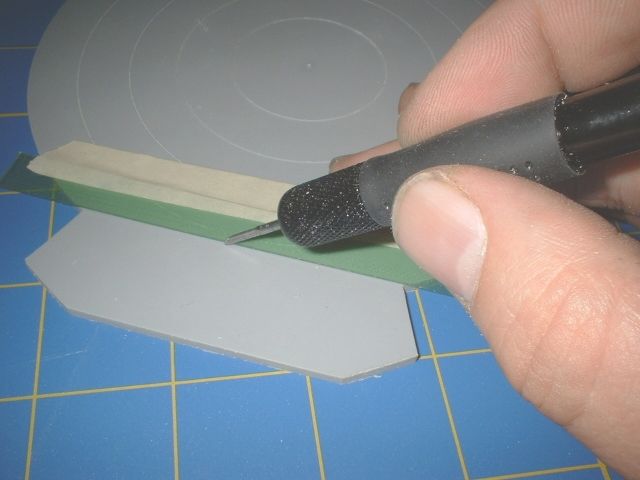
For some details I make templates from scrap styrene. Use a round tipped scribe to keep from damaging the template and start with light passes to establish the groove.
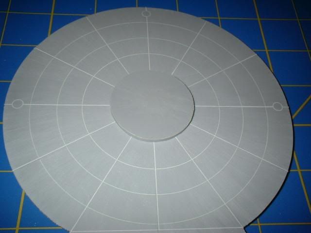
Here is the top side of the saucer section all scribed. Note the bridge section is just sitting on the saucer. It is still just a basic shape needing to be chamfered, bridge dome added, and scribed. Now to do the otherside of the saucer.
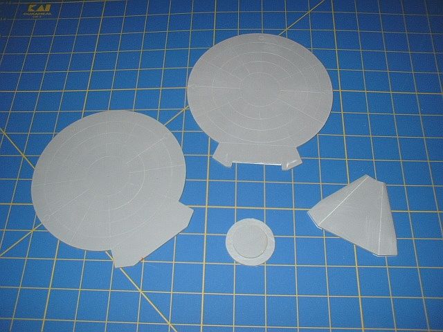
Here are the main pieces of the saucer section ready for assembly.
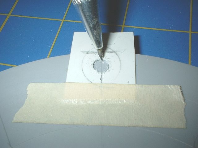
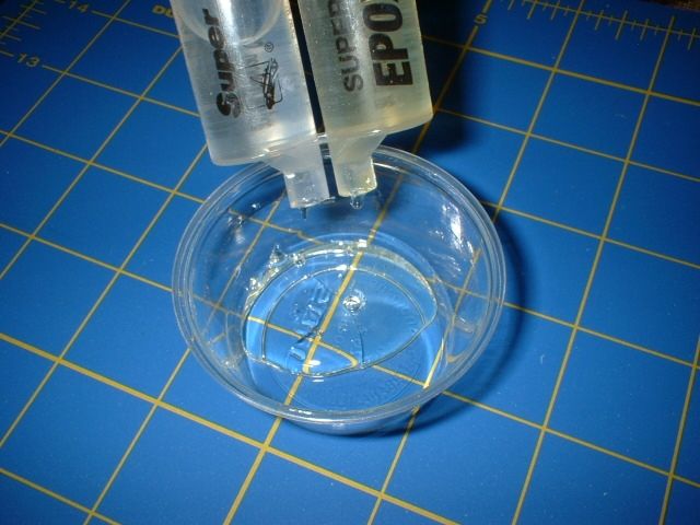
In the picture above you see a small disc epoxied to a slghtly larger one. This is what will be at the center of the disc to give it that slight convex shape I’m looking for. I glued them into place using this two-part 90 second epoxy. I also placed a dab in the center of the impulse drive area, for strength.
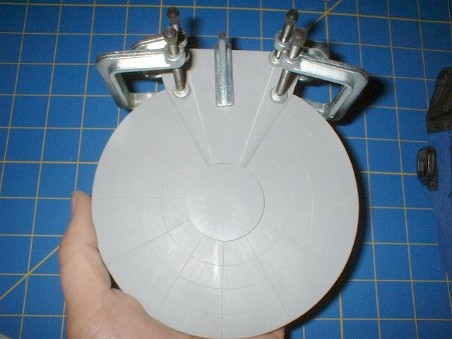
After carefully aligning these four parts, I placed clamps all the way around the assemblies circumference. I started at the impulse drive, as shown in the picture, and worked my way around the whole saucer checking alignment as I went. After the epoxy had set for an hour I backed pressure off the clamps until the saucer halves opened just a hairs width. I then place a drop of CA glue at each clamp location. The capilary action suspended the glue between the two halve until I reclamped that area. I went around the whole saucer in this fashion.
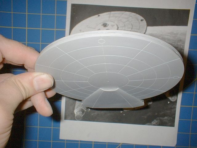
The bandages come off and I check to see if there is still a family resemblance. LOL[:p]
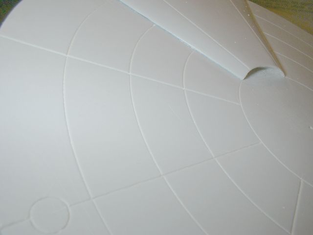
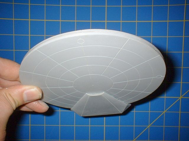
A couple close ups of the saucer underside.
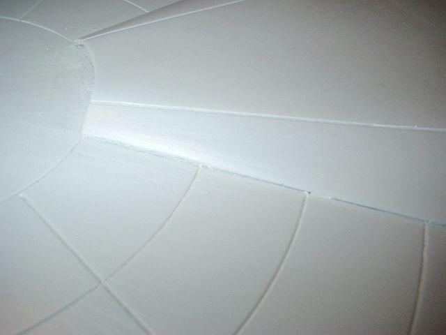
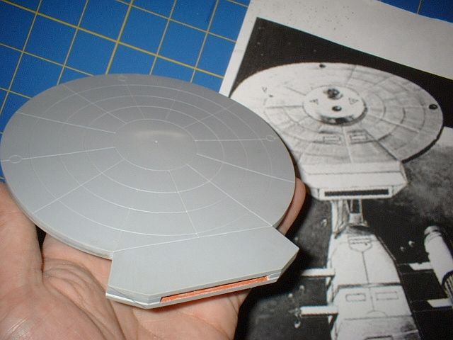
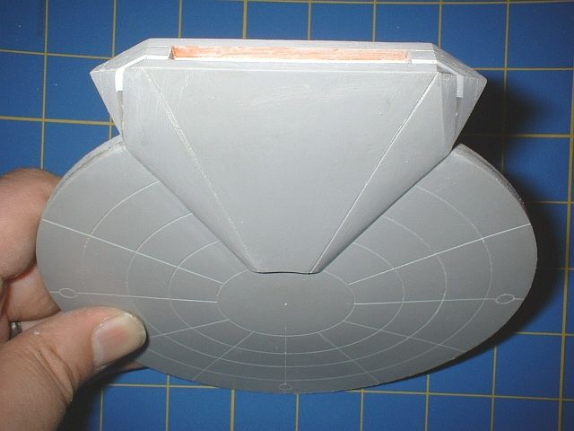
Here is a view of how I treated the underside of the impulse section. The wedge shape is meant to echo the shape of the engineering hull and help give a sense of speed. There is no official view of the underside of the Baton Rouge class of starship so I was on my own here. How did I do?
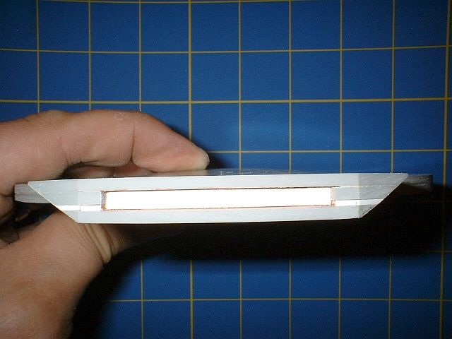
I reshaped the sides of the impulse section to match the painting. The open rectangular area is were the impulse exhaust will fit. In the kit hopefully I’ll cast it from clear red tinted resin.
A couple more angles of the reshaped impulse section sides. Note that I haven’t installed the bridge or sensor pallet yet.
Well there you go, I’m not dead and I’m actually making some head way. [:D]