UPDATE 1
Hi Everybody!
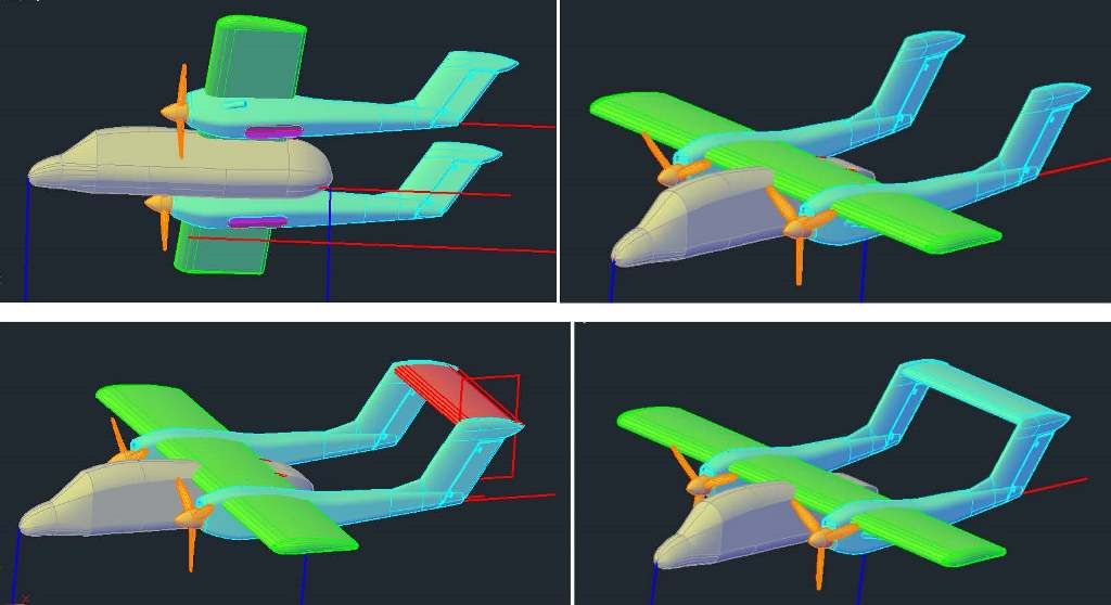
Well, my license must have expired, but I reinstalled the latest AutoCad and everything is working now. I redid the work I lost on the boom and added the vertical tail, as shown below…

Next I added the transition section between the boom and tail (top images, below) and added the part of the foremost segment of the boom (lower image).
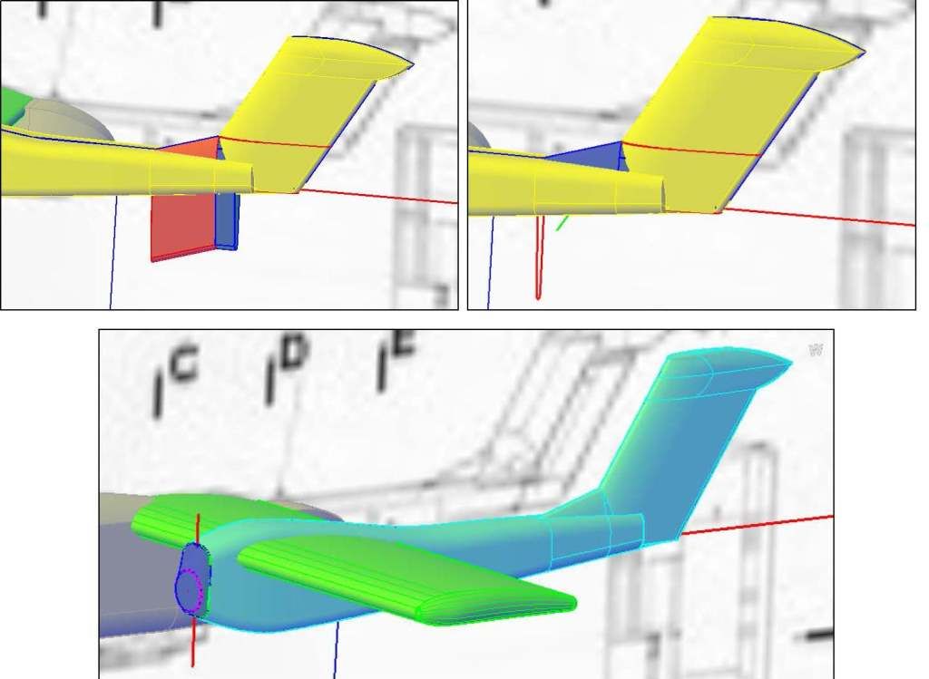
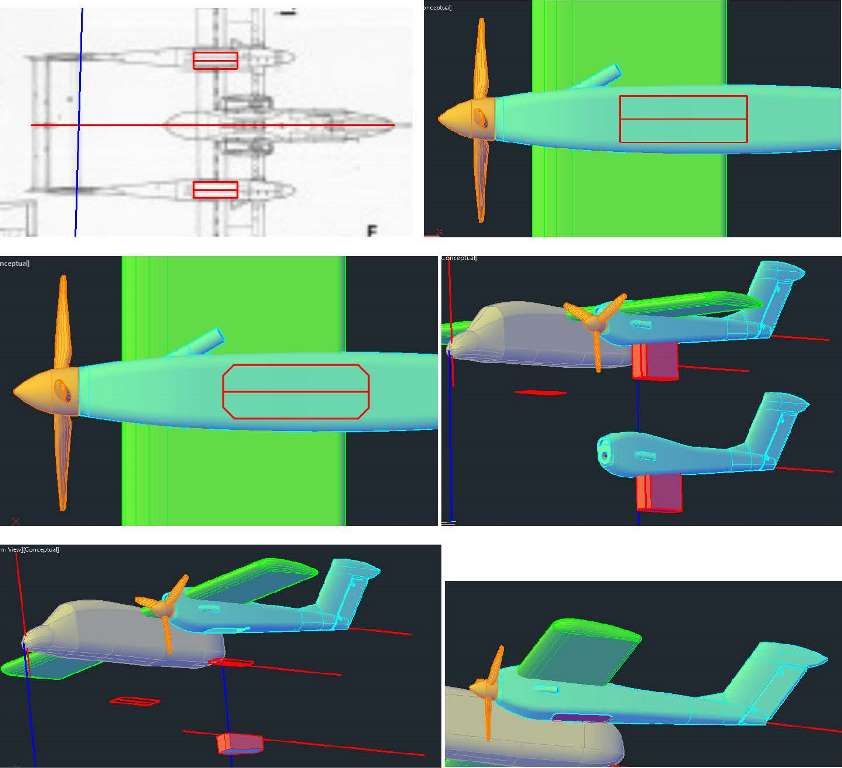
After this, I made the top part of the foremost segment of the boom (upper left image, below), extruded a closed polyline I made for the intake (upper right), then using the subtract command cut out the intake (lower left). At this point I copied a propeller I had made for the 1/144 scale Cessna 421 (http://cs.finescale.com/fsm/modeling_subjects/f/48/t/162600.aspx), and scaled it up just slightly (lower right).
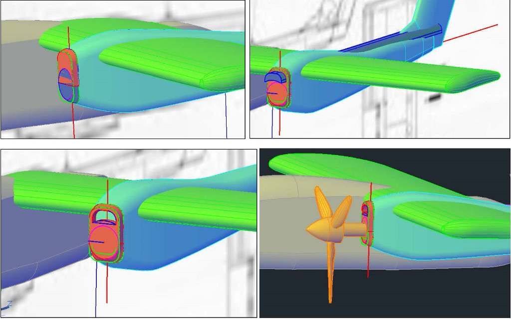
After moving the propeller into position, and cutting a recess for it out of the boom, I decided to redo the aft end of the boom extending it further aft.
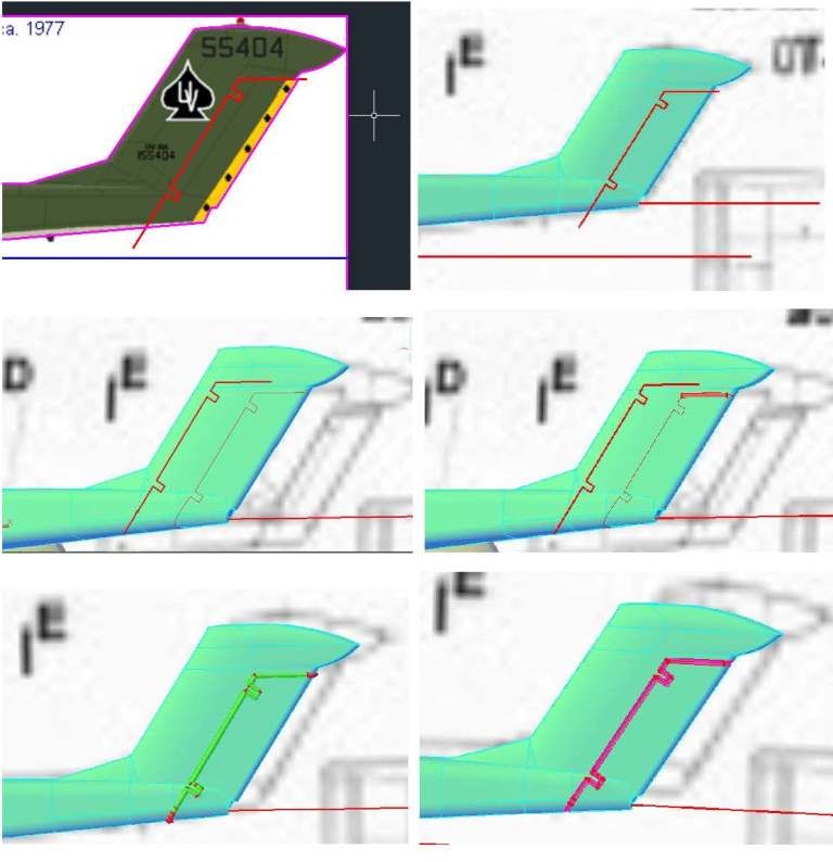
Next I added the exhaust pipe on the side of the boom. The image below show the tracings made on the Wings Pallette plans and copied to the model. There is a circle, a line and an ellipse. Note that I had to change the elevation of the lines so that they appear above the model.

To aid in construction of the exhaust pipe, I used another handy AutoCad command, Project Geometry and projected the tracings onto the boom. I then copied the line I had projected onto the end point of the projected line, rotated the line out away from the boom about 30 degrees, and drew a circle perpendicular to the line, on the end of the line (upper left image, below), and extruded the circle along the rotated line (upper right). The pipe was too far back, so I moved it forward slightly and added the collar by lofting between the ellipse and another circle part way up the tube (red in lower left image). The lower right image shows it after I used the union command to join the parts to the boom.
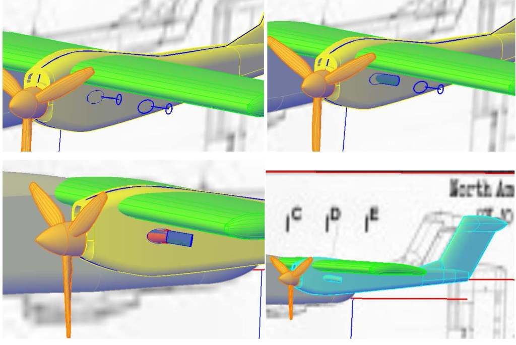
Next, I started the surface detailing by tracing the outline of the rudder from the Wings Pallette plans (upper left image below), copying the tracing to the model (upper right), and projecting the tracing unto the tail (middle left). To “etch” surface details I create solid tubes along the projected lines, using extruded and lofted circles, which I then subtract from the solid, leaving a channel cut in the surface of the solid. I typically make these using 0.004”-0.006” radius circles, with the absolute minimum being 0.003”. In this case, the model is currently at 1/144 scale, but I want to be able to print it at 1/350 scale, so I used a 0.0075” radius circle. The middle left image below shows the beginnings of the tube. The lower left shows the completed tubes. Note the bottom and aft parts are red and not joined to the rest of the tube in green. This is because I could use symmetry to save time and mirror imaged the green bit to the other side before joining all the parts together. The lower right image shows it after I subtracted the tube.
The last remaining detail that needed to be added to the boom was the main gear housing and doors. I started, as usual by tracing them on the plans (upper left image, below) and moving and rotating one to below the boom (upper left). After chamfering the corners (middle left), I extruded it into the boom and copied it, the boom and a reference line down a bit (middle right). I then used the subtract command to create a cavity in the boom, and the intersect command to create a plug (lower left), that I moved up into the boom (lower right). Part of this plug will be used to make the gear doors and some of it will be rejoined to the boom, but this will be done differently for 1/350 scale than 1/144 scale, so this is as far as I wanted to go at this point.
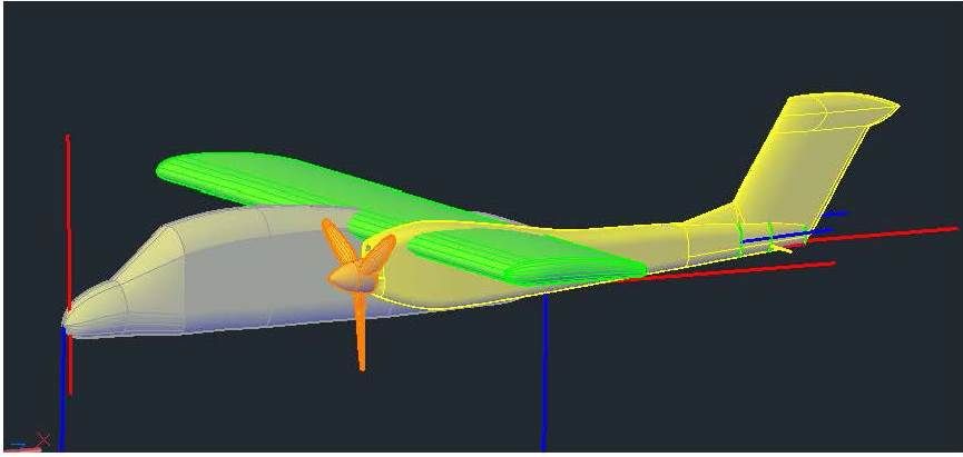
At this point I mirrored the boom, plug, and prop to the other side of the fuselage (upper images below), and made the horizontal tail (lower left). To make the tail, I extruded a copied and scaled wing section. The lower right image shows it after I joined the booms and horizontal tail.
The last thing I did this session was cut out the canopy section, which will be printed in clear glass. I traced it from the Wings Pallette plans and copied it to the model (upper left image, below), extruded the polyline through the airframe (upper right), and used the slice command to slice the airframe along the extruded polyline (lower).

To be continued…