Happy New Year Everybody!
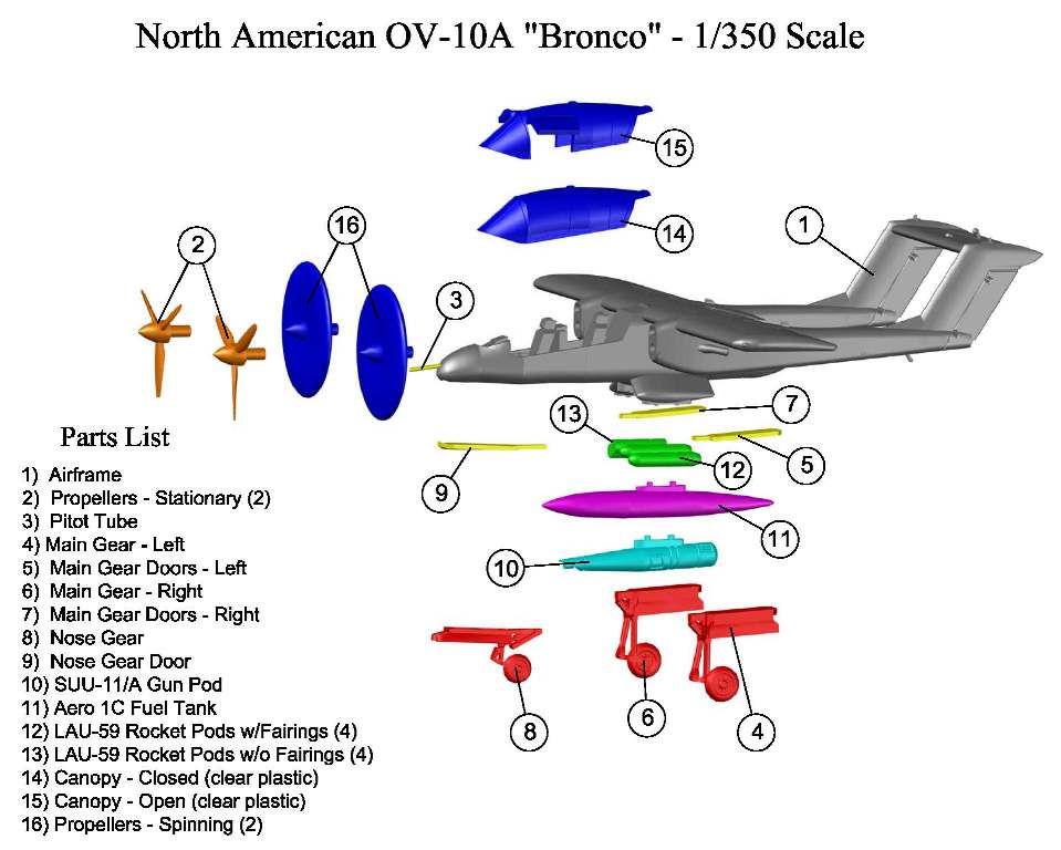
This Christmas I learned that my brother in law spent many hours in the back seat of an OV-10 when he was in the Marines. Since I have gotten into making small scale model kits using AutoCad, and having them 3D printed, I decided I would make a display of the OV-10 to give him next Christmas. I also decided to document the process by posting the WIP on this Forum.
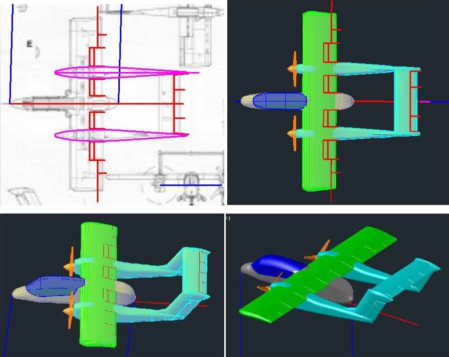
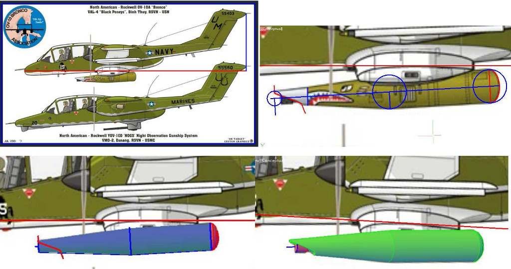
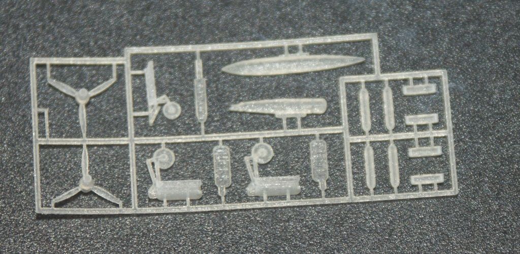
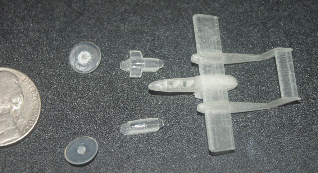
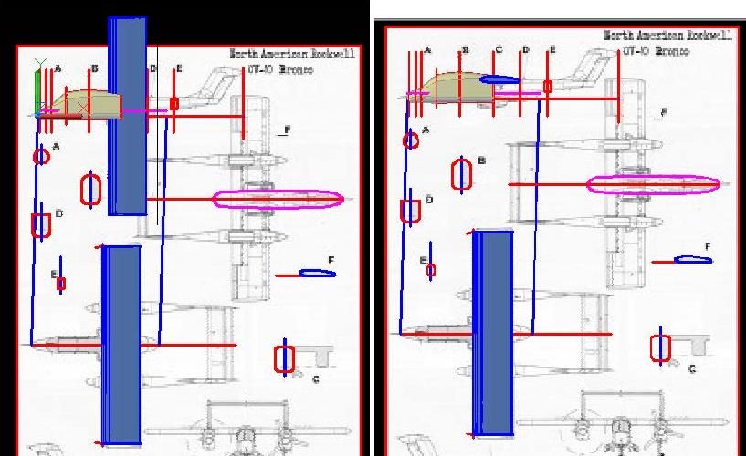
At this point I have not yet decided how I’m going to display the model, or even whether I’m going to make it in 1/350 scale, or 1/144 scale, but it doesn’t matter yet. The initial process is the same. I start by looking on the internet for the best set of plans I can find. Usually, I can find fairly decent plans with 3-views and cross-sections of the fuselage, and sometimes the wings, stabilizers and nacelles. For the OV-10, the best plans I could find have 3-views, 5 cross-sections of the fuselage, and one wing section, but the image is of very low quality. Still, since they were the best I could find, I started by importing the image of the plans into AutoCad and scaling it to size.
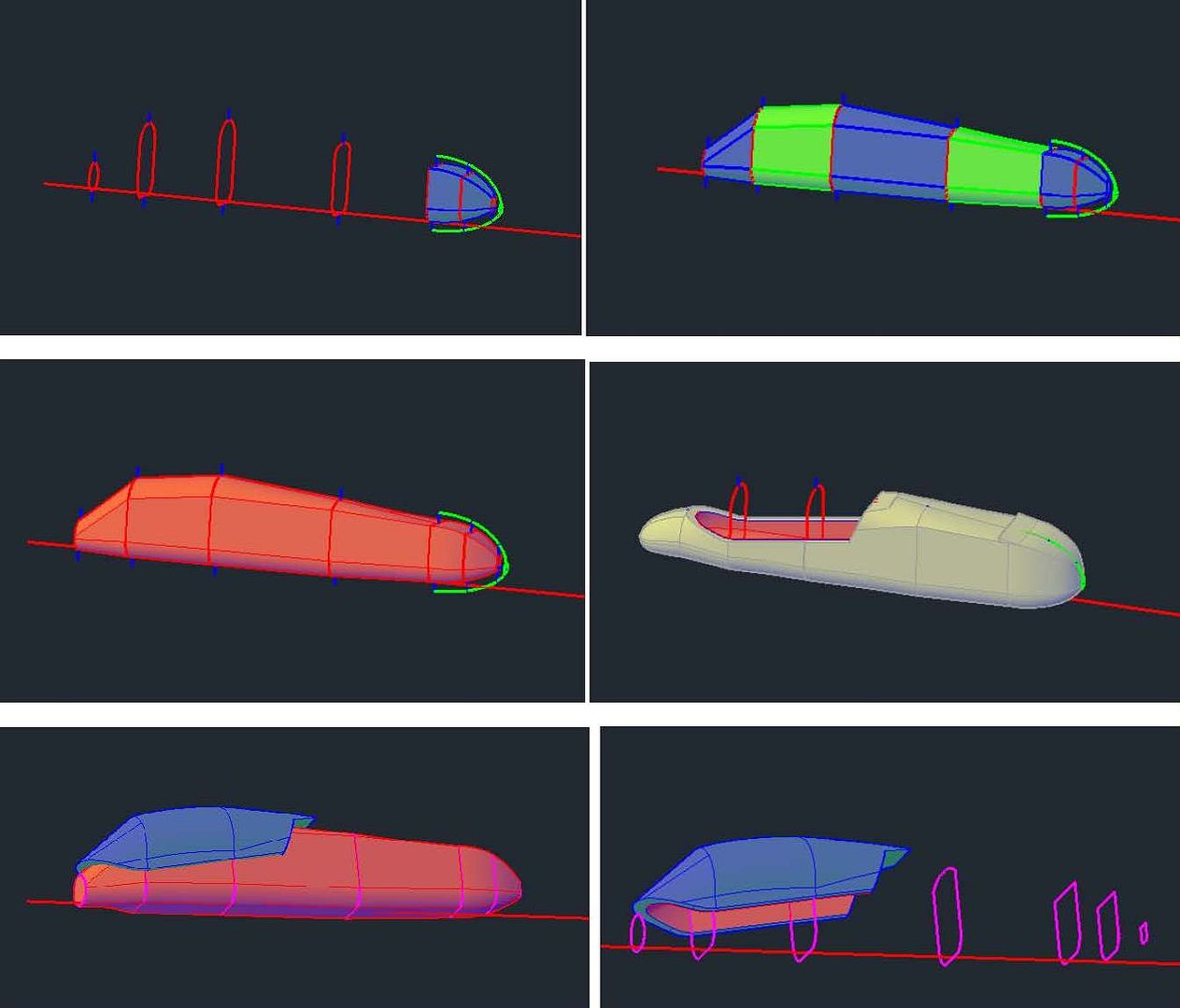
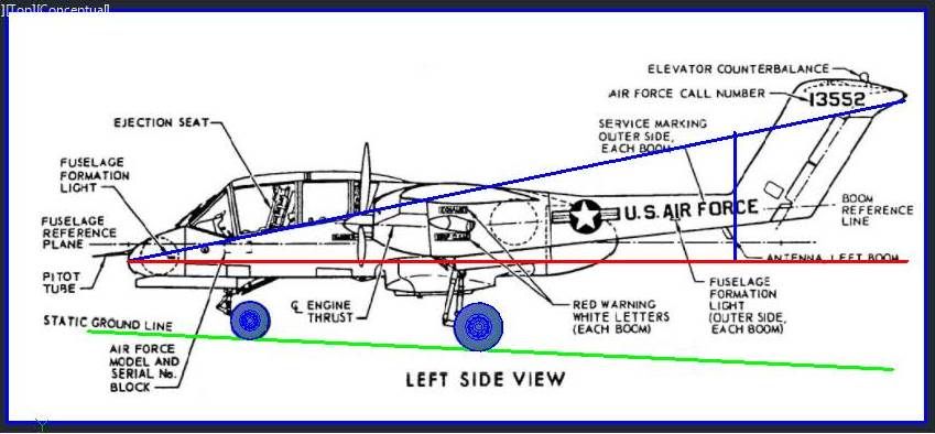
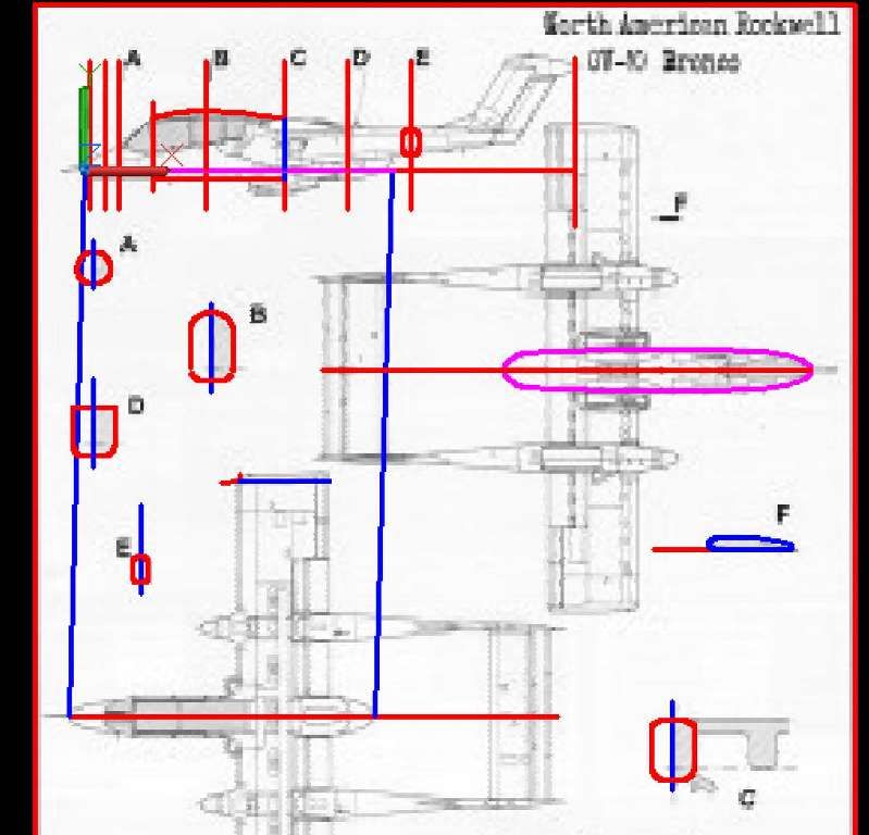
Even though I am leaning towards making the display in 1/350 scale, I decided to make the initial model at 1/144 scale. The length of the OV-10 is reported to be 41’ 7”, which at 1/144 scale is 3.47”. With the plans scaled so that the length of the aircraft was 3.47”, the next thing I did was trace the sections, the best I could from the fuzzy plans, as seen in the image below. When drawing the sections, I only drew one side, then used the Mirror Command to mirror it to the other side of the center axis. I then used the Join Command to create closed polylines for each section. Note that I also traced the top view of the fuselage and the location axes for the sections.
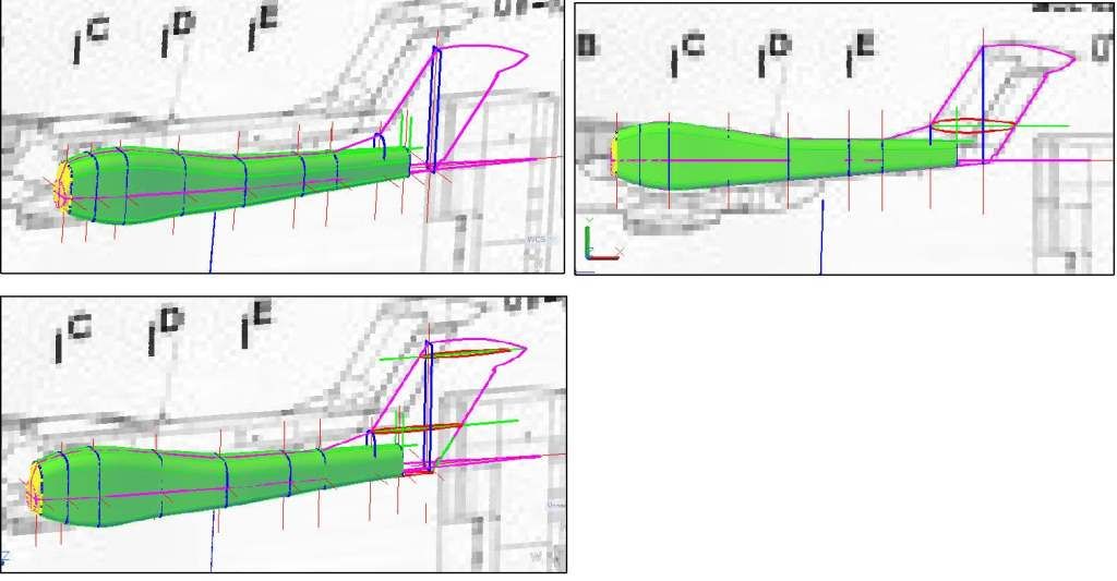
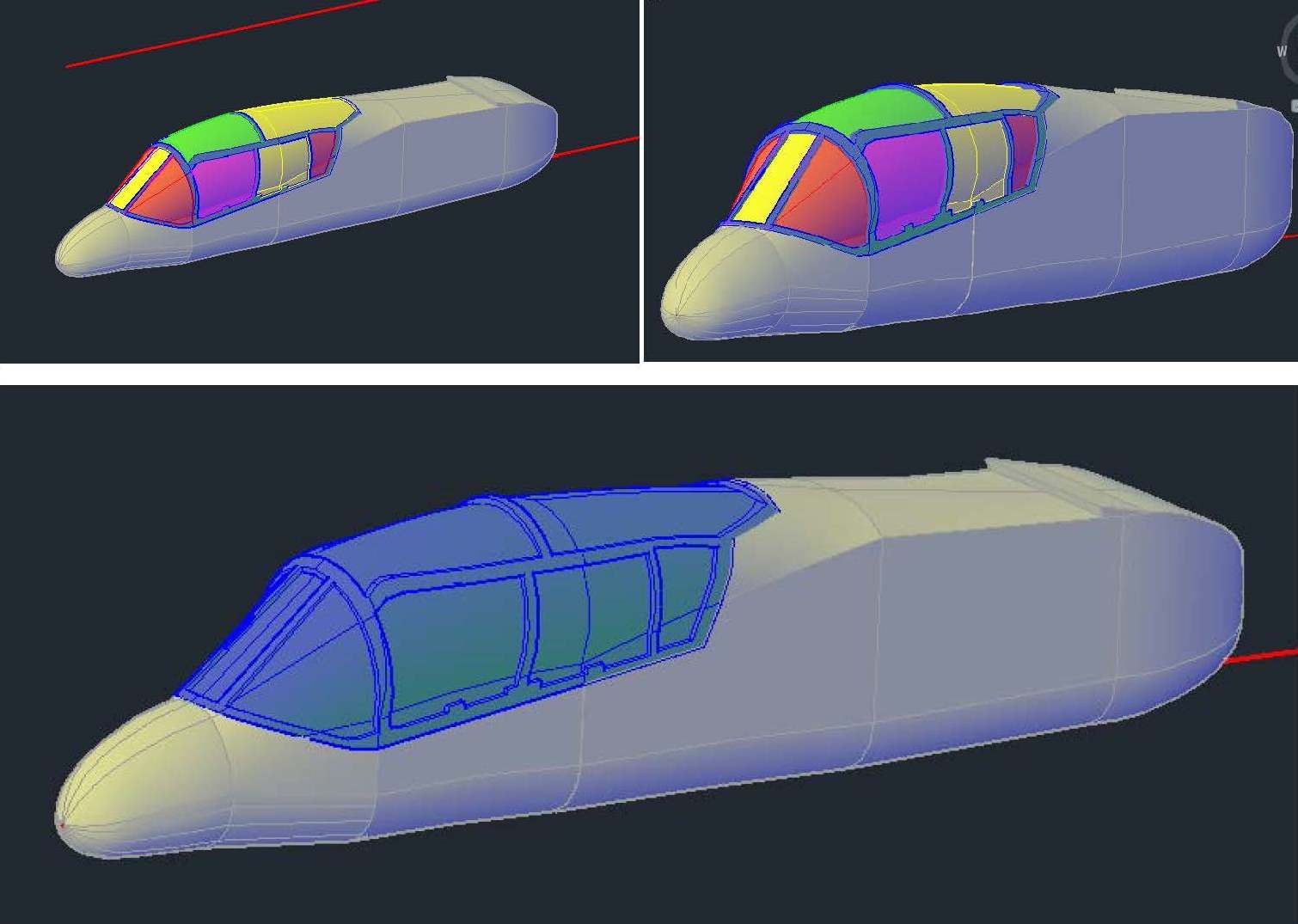
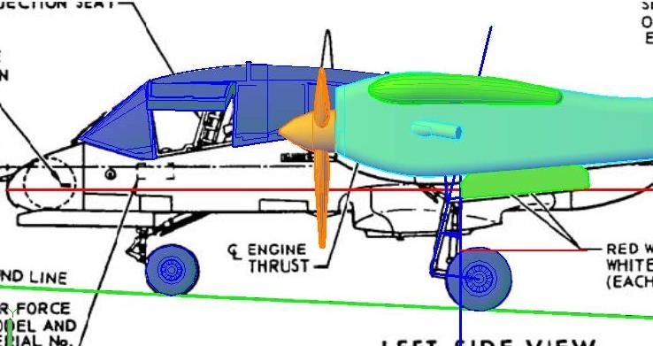
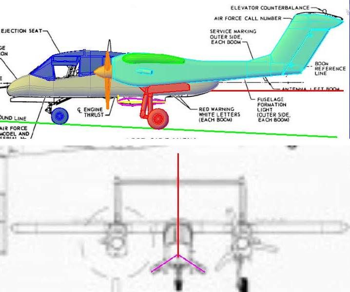
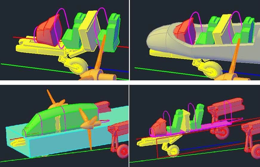
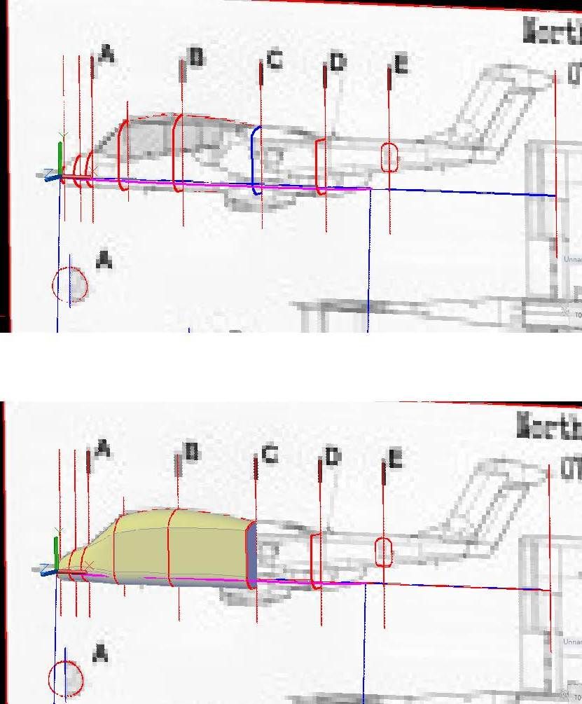
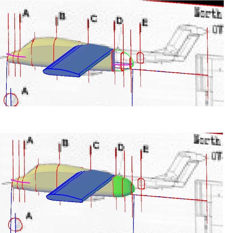
In the top image below you can see the sections copied to their respective axes and rotated 90o (except for section E). Note that I have added 3 sections forward of section A (axes only shown for 2 of the sections) to define the nose, and another section between sections A and B to define the wind screen. The sections forward of section A are just scaled down versions of section A (except the very end section that is a small circle). The section between sections A and B was made by copying section B to the break point on the wind screen (at the top), trimming the vertical lines, moving the lower bit up to match the lower fuselage in the plans, then rejoining them.
To make the sections a “solid” I used the Loft Command as shown in the lower image below. To properly loft between the new section and section B and between sections B and C, I drew arcs defining the upper fuselage and lines defining the lower fuselage and used them as guides.
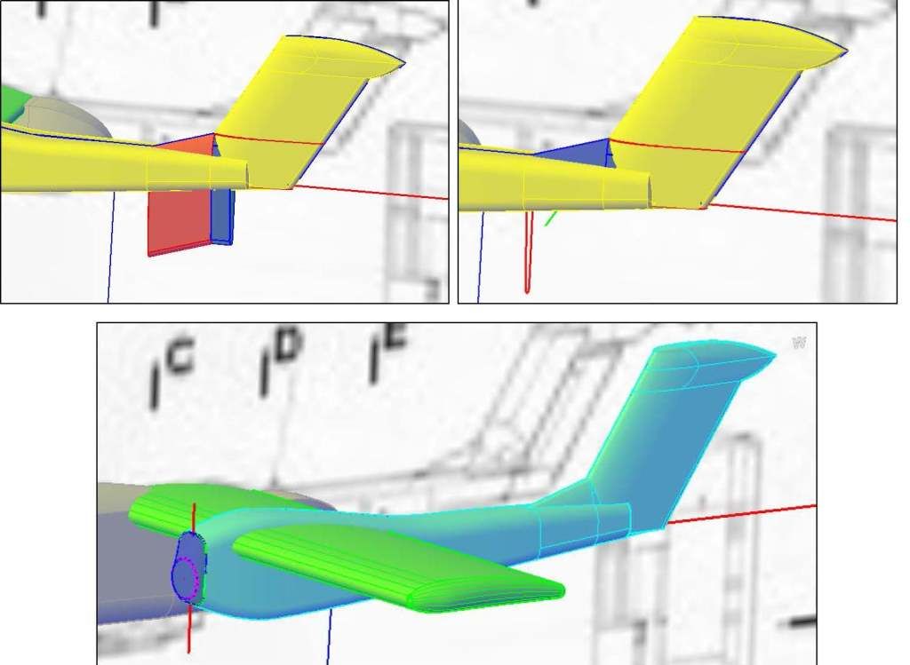
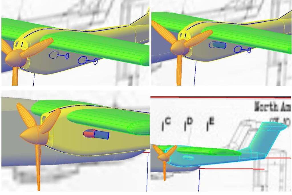
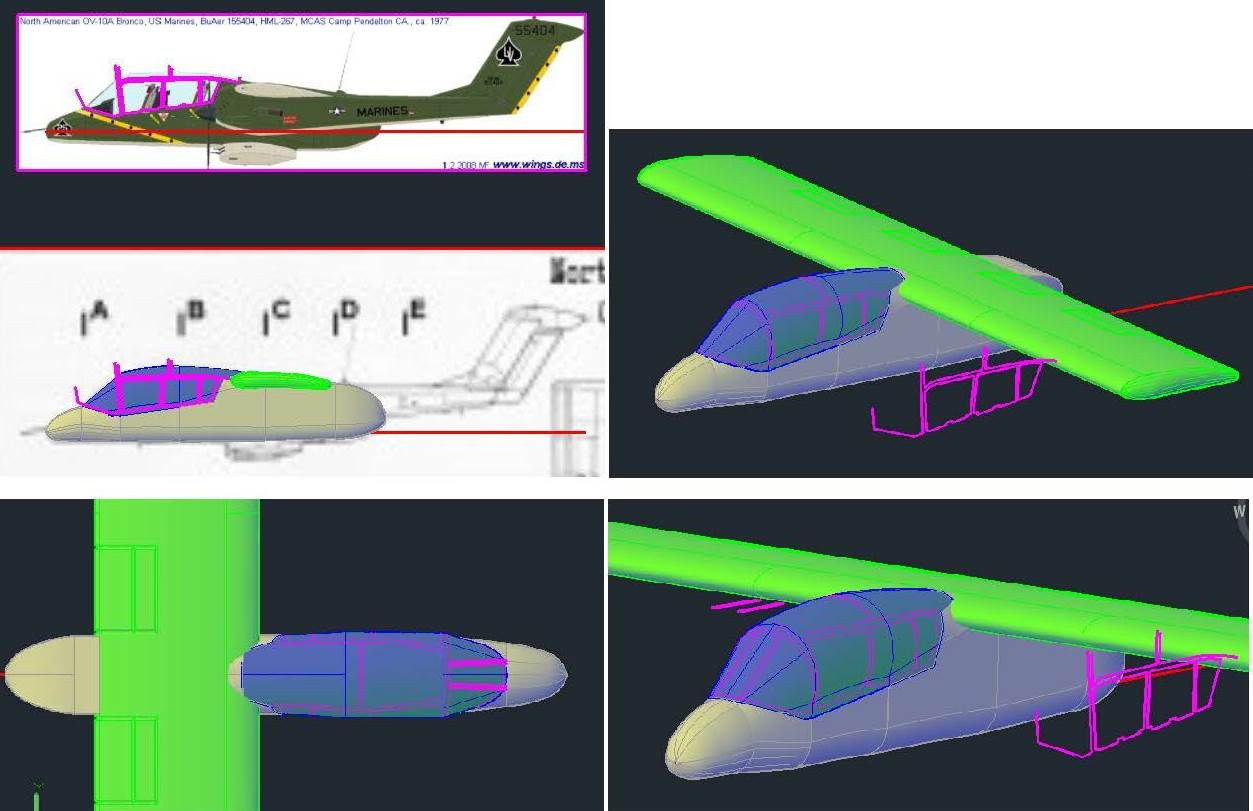
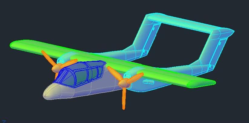
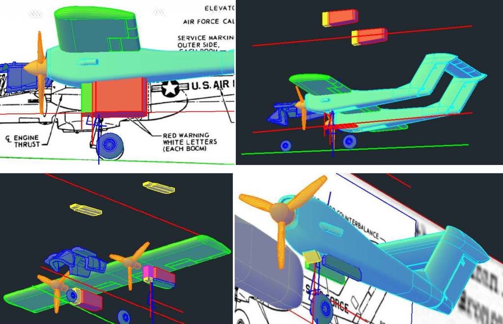
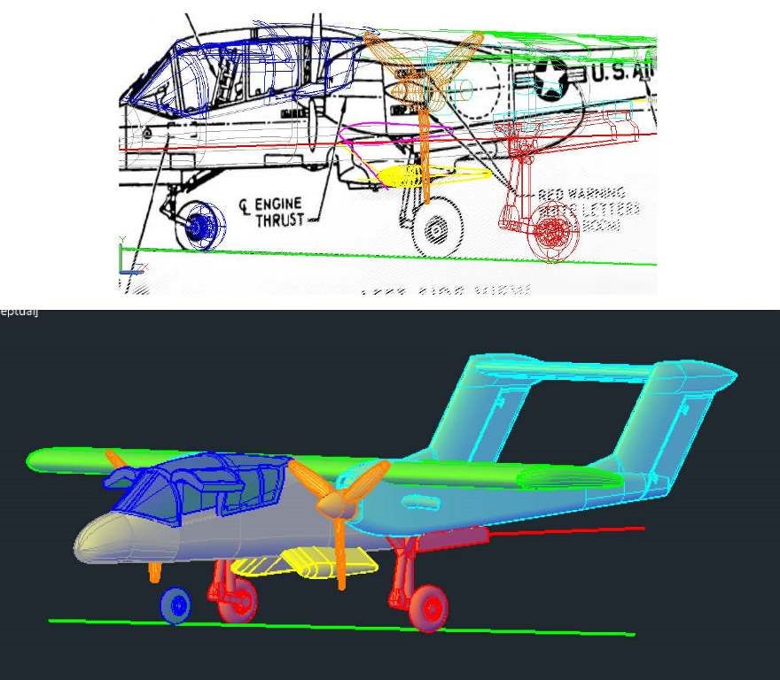
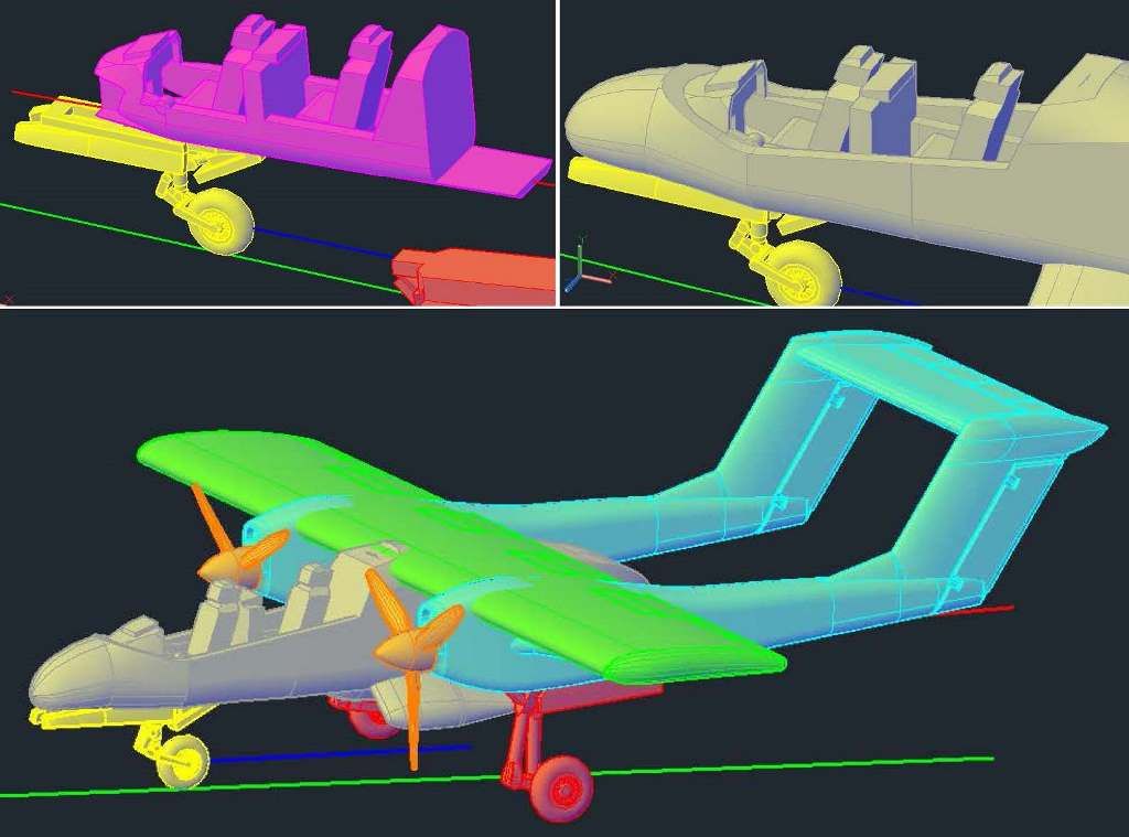
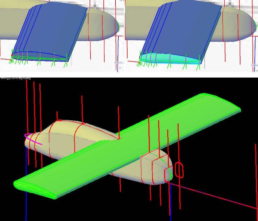
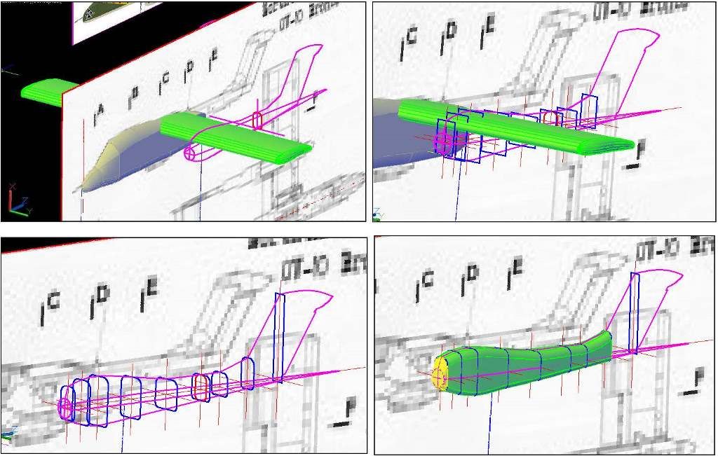
The images below show construction of the wing. The image on the left shows the wing as it was traced from the plans and copied to the airframe. The image on the right shows it after the wing has been rotated 90o and positioned properly vertically.
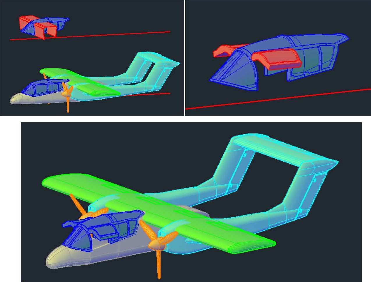
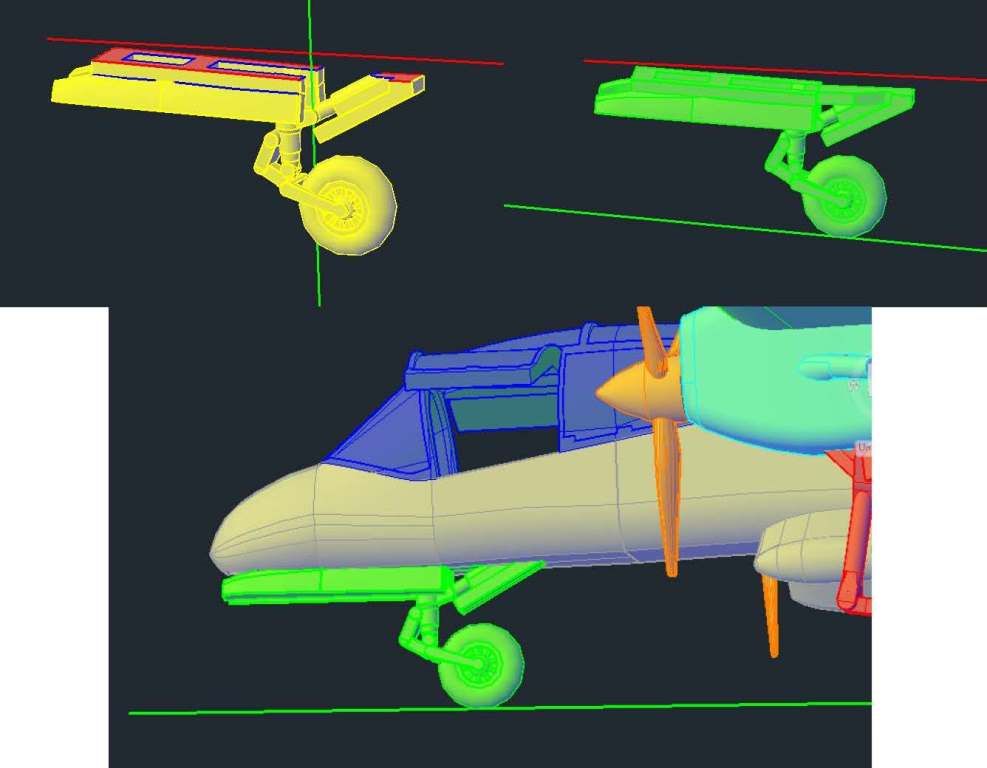
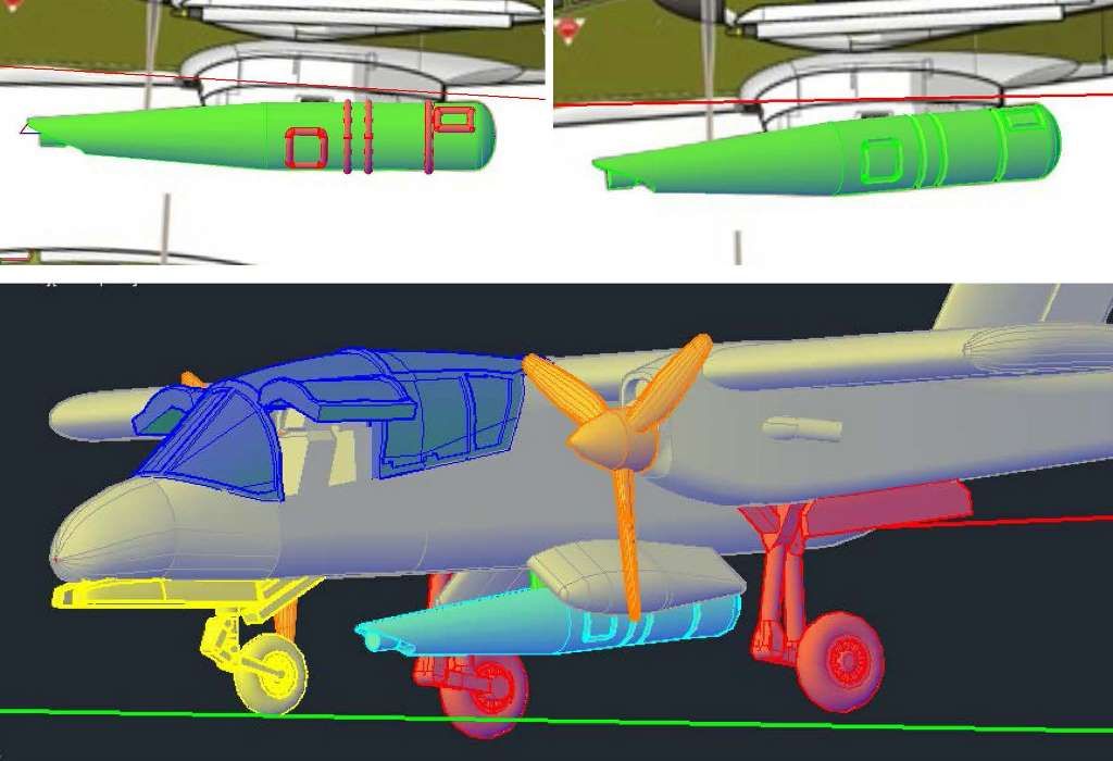
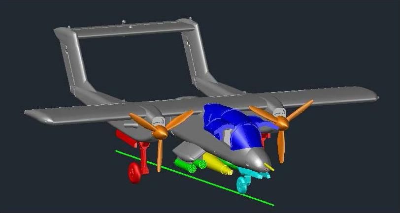
The images below show the wing in position and the sections I had to make to complete the fuselage.
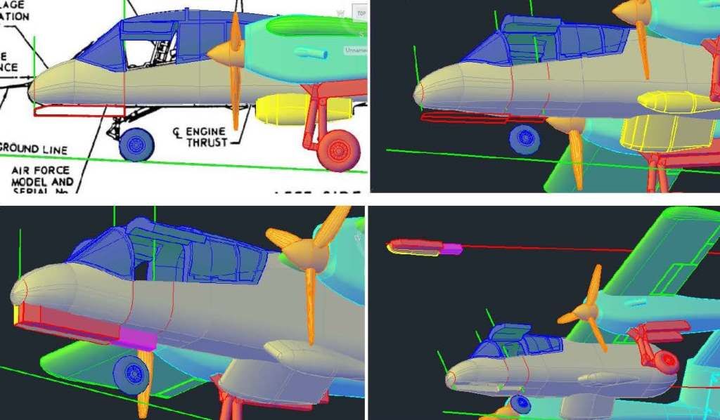
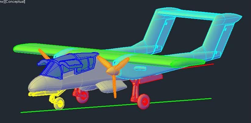
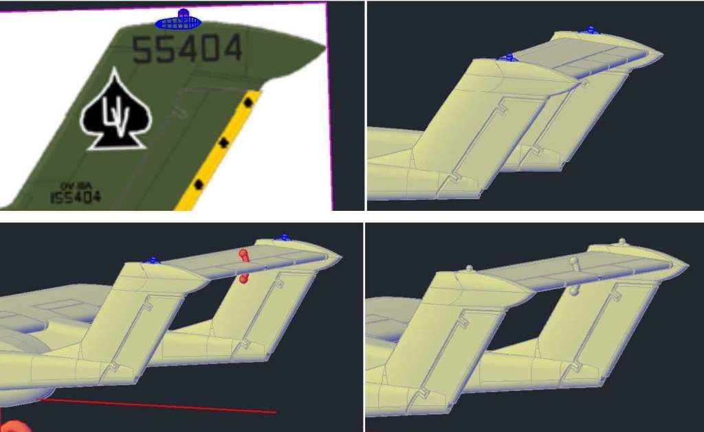
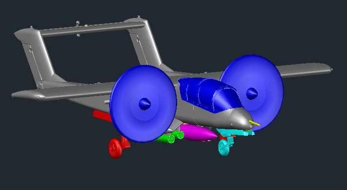
The wing tips at this point were blocky, and wings aren’t like that, so I rounded the tips by lofting multiple ellipses together and joining them (along with a sphere at the tailing edge) to the wing using the Union Command, as shown in the images below.
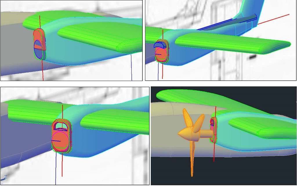
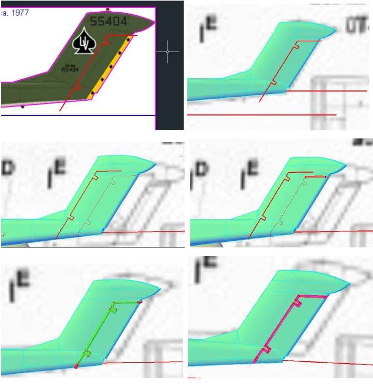
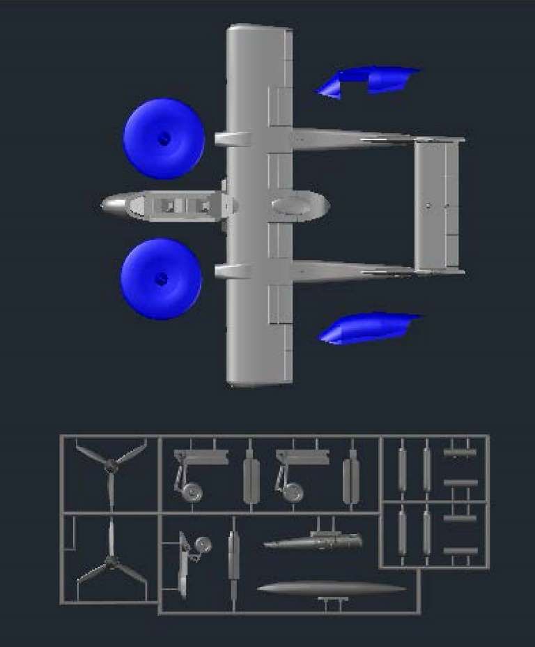
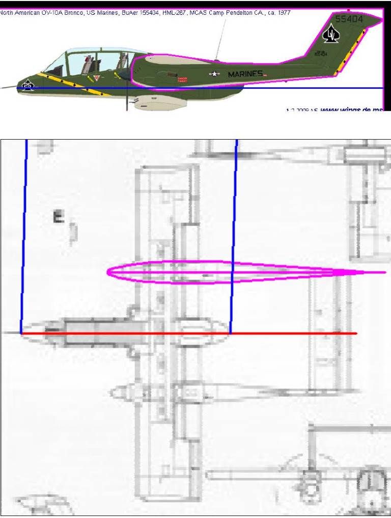
Due to the difficulty of distinguishing the boom outline on the plans, I found a good side view of the OV-10A and imported and scaled it to size, then used it to trace the boom. I traced the top view from the original plans, as shown in the images below.
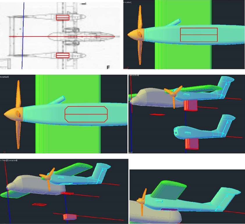
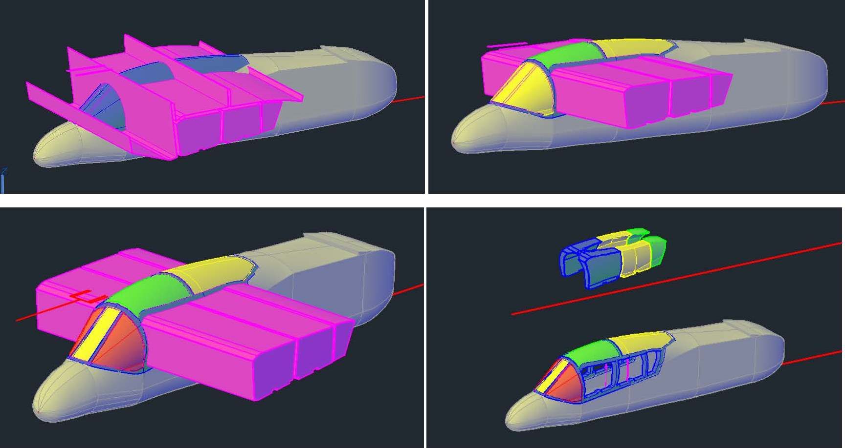
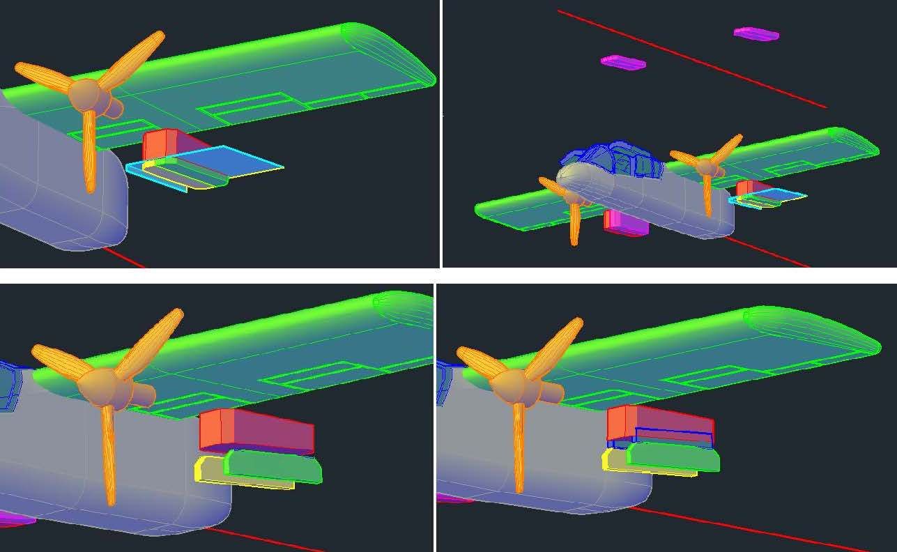
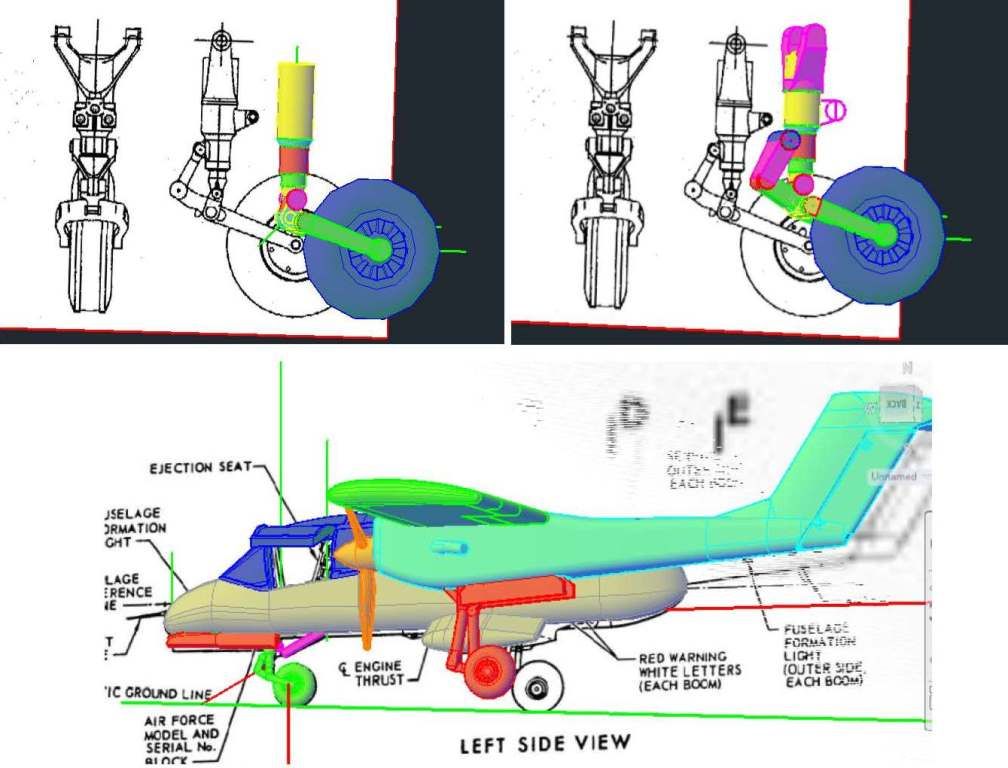
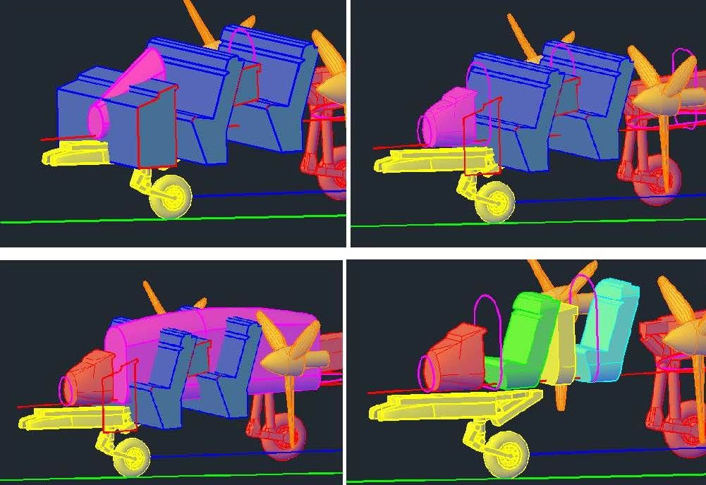
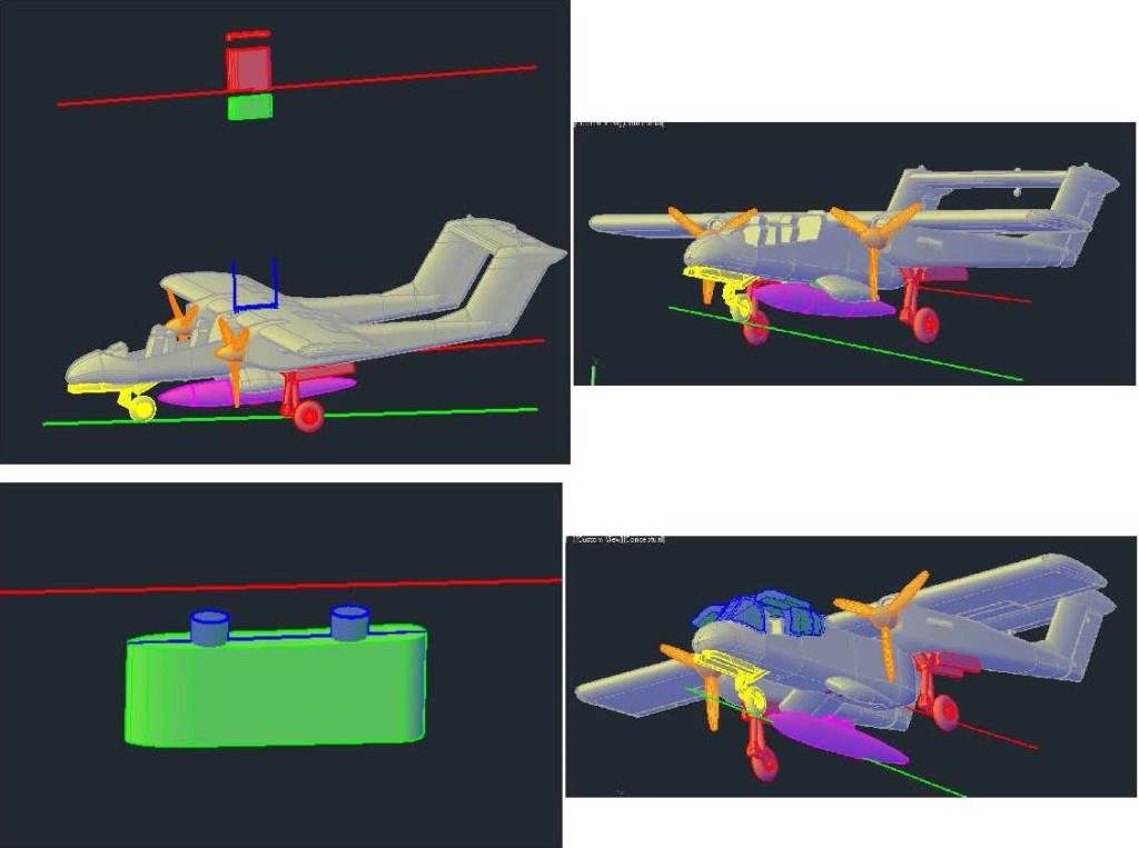
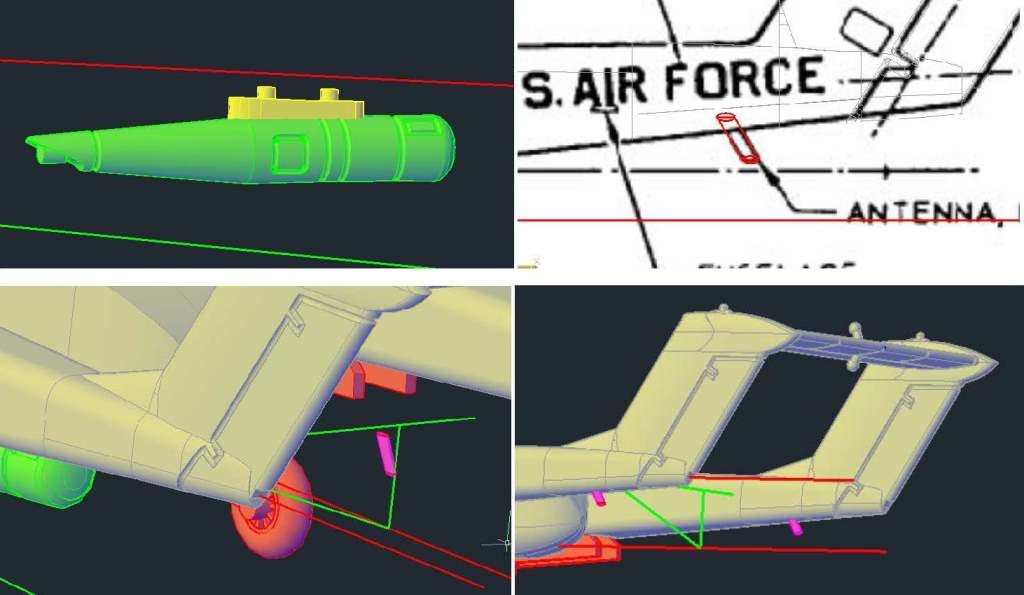
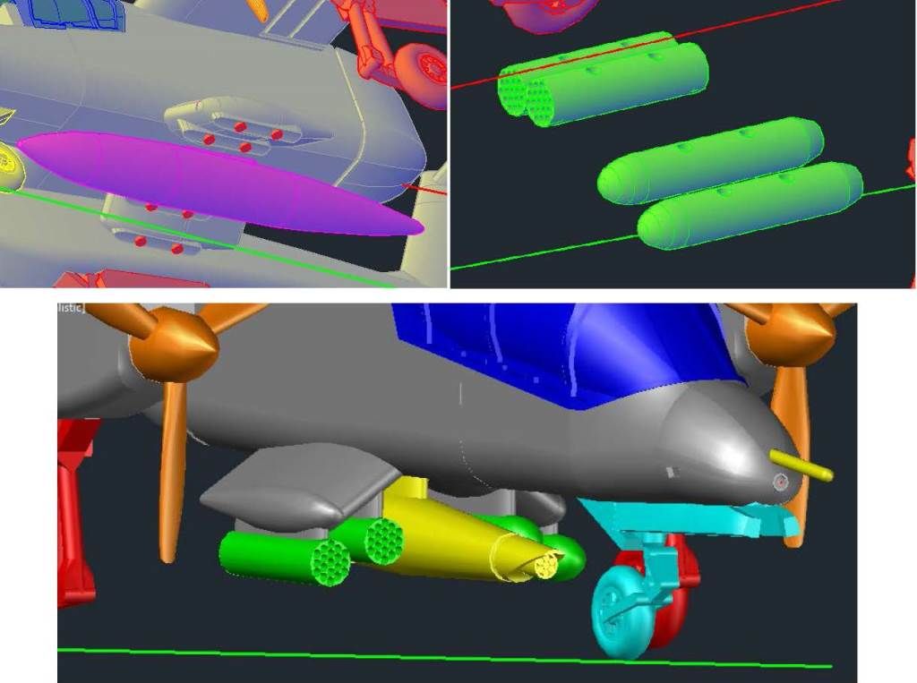
The images below show construction of the boom. In the upper left image the boom sections have been copied to the proper location on the left wing. Next I created rectangles along the axis of the boom using the sections to define the boundaries (upper right), then “filleted” the lower corners to 0.04” and the upper corners to 0.05” (lower left). The lower right image shows it after I lofted the newly created sections together.
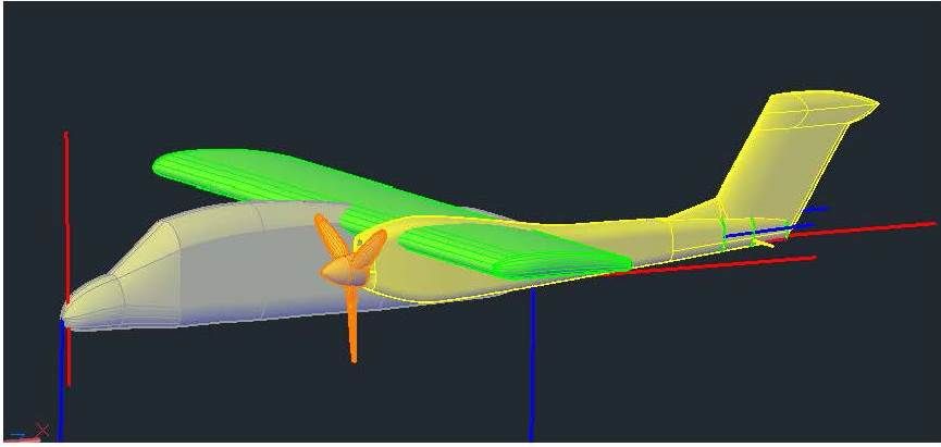
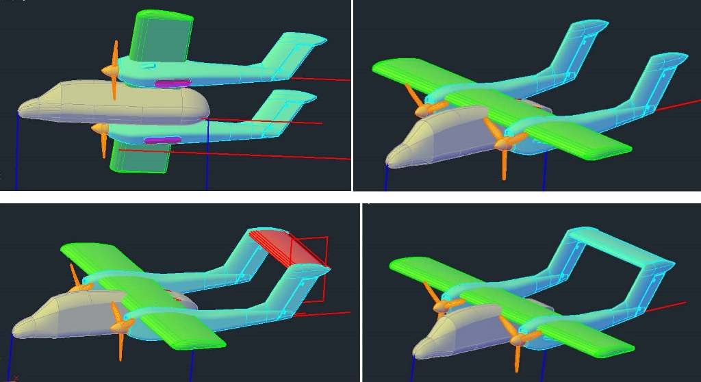
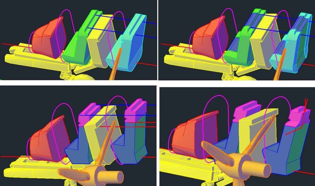
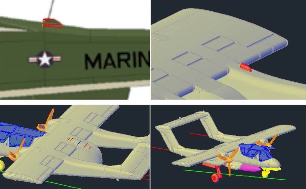
Looking at pictures of OV-10’s, I realized that I didn’t have the end of the boom quite right, so I lopped off the end and made a new section so that the boom would continue to taper, as shown in the upper left image. Next I created a section for the stabilizer portion of the boom, as shown in red in the upper right image. I then copied the section up and down along a line defined by the leading edge of the stabilizer, as shown in the lower left image, and lofted between the sections. Unfortunately, as I was rotating the image to align it for a snap shot, AutoCAD froze up and I lost all of the work I had done on the boom. I’m not sure why this happened, but it may be due to an expired license. I’ll continue on the model and let you know what the issue is when I get it sorted out.