Yeah there is not much to this thing. Though there are some fit issues, I am enjoying the heck out of building this.
Surely glad to hear that. They say this hobby is supposed to be fun, you know. That’s what I hear, anyway.
In answer I think to your question about why the interior corners of the deck opening aren’t square, here’s why.
Older molds, in other words everything not made in the modern slide molds which have moving parts, need a “draft” on every part in order to separate the halves of the mold and remove the part from the remaining half.
So no parts can be exactly square to the opening and closing of the mold halves.
This looks like a fun model. Painting it will be really cool.
Images ?
I am lucky if I spell right . No really . Many folks have been kind enough to try to splain this pichure ting .Just can’t seem to get the hang of it . I still am trying .
Maybe I’ll shock the H&** out of meself one day and actually get one on here .Whoo that would be so cool . T.B.
You are pretty knowledgeable about this stuff, GM. Thanks for explaining that. It is good to know that it is not anything that I did.
Comes from building too many ship models in the 60’s with Aztec steps.
Nice job overcoming the problems,looks good.
Thanks, Tojo.
Last night I had worked on the sail and what should have been an easy deal turned into a bigger job. I will update on that within the next few days.
GM, that explains it then. You have a long history of building challenging models!
Yeah that is what they say. [:)]
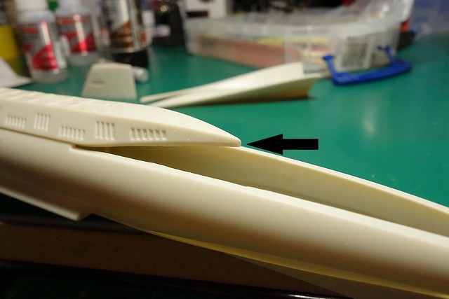
Here is something that started out well. Both halves of the sail assembly came together very nicely, and I thought that I was heading for a slam dunk. But, not so fast. When it came time to install the top piece it became apparent that I had a fit issue to deal with. The image shows the problem. There is more though. The top piece was too wide as well.
So, this was going to require some shaping, which I did. I took it a step further by filling in that join with CA. I searched the internet for Seaview images and all the images that I could find appear to show the sail as one piece. In other words, there is no top piece creating a join. I was glad about this because the filler helped me bring the assembly to the shape that I was looking for. I was struggling to get there without it.
Aside from this, I worked on filling the gaps on the keel. Tomorrow, I will work on filling the joins on the top deck.
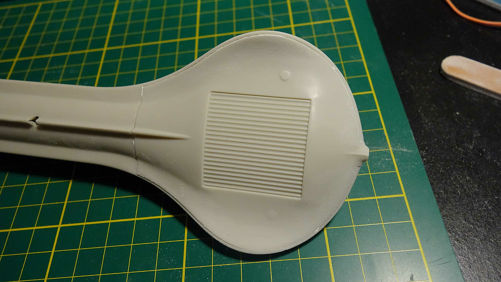
Here is 4+ hours work of filling and sanding bliss. This was painstaking because there is not a lot of room to work with having those hatches so close to the join. I did not want to mess up those missile hatches.
I used CA to fill the gaps. CA dries relatively clear, so it is hard to gauge from the photo what has been done. Because of that, it looks like there are still some gaping gaps. Heck, even to the human eye it is hard to see. I had to position the lighting to see how it reflects, and I also used my fingernail to feel for ridges. I won’t really know how well this turns out until I hit it with some primer. I think that I have it pretty close though.
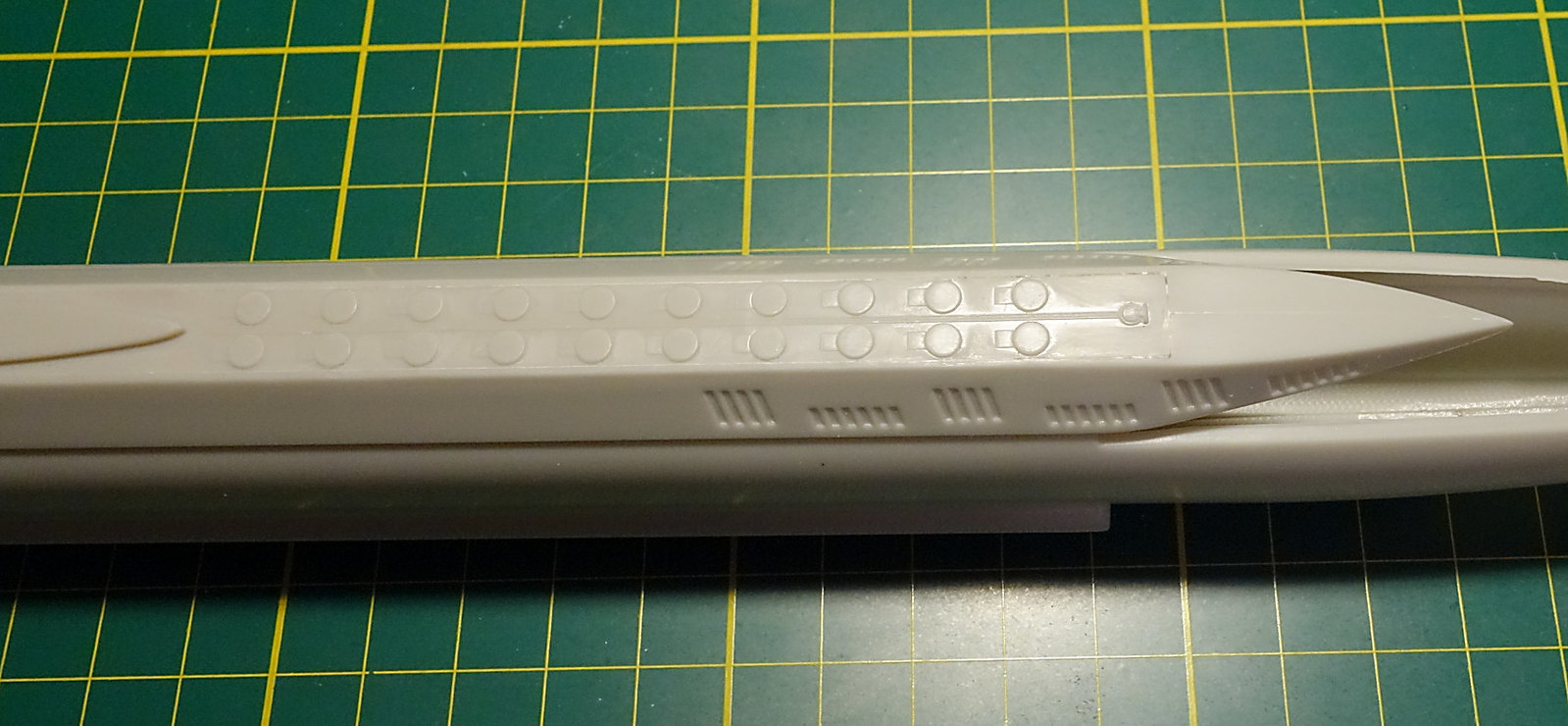
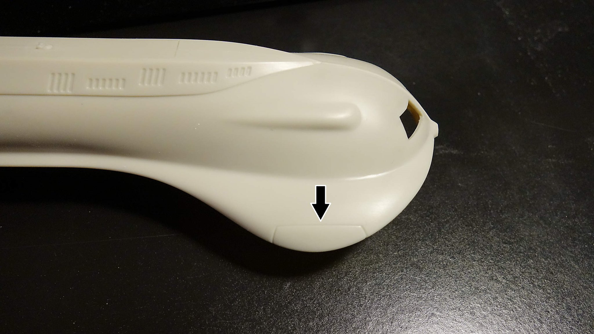
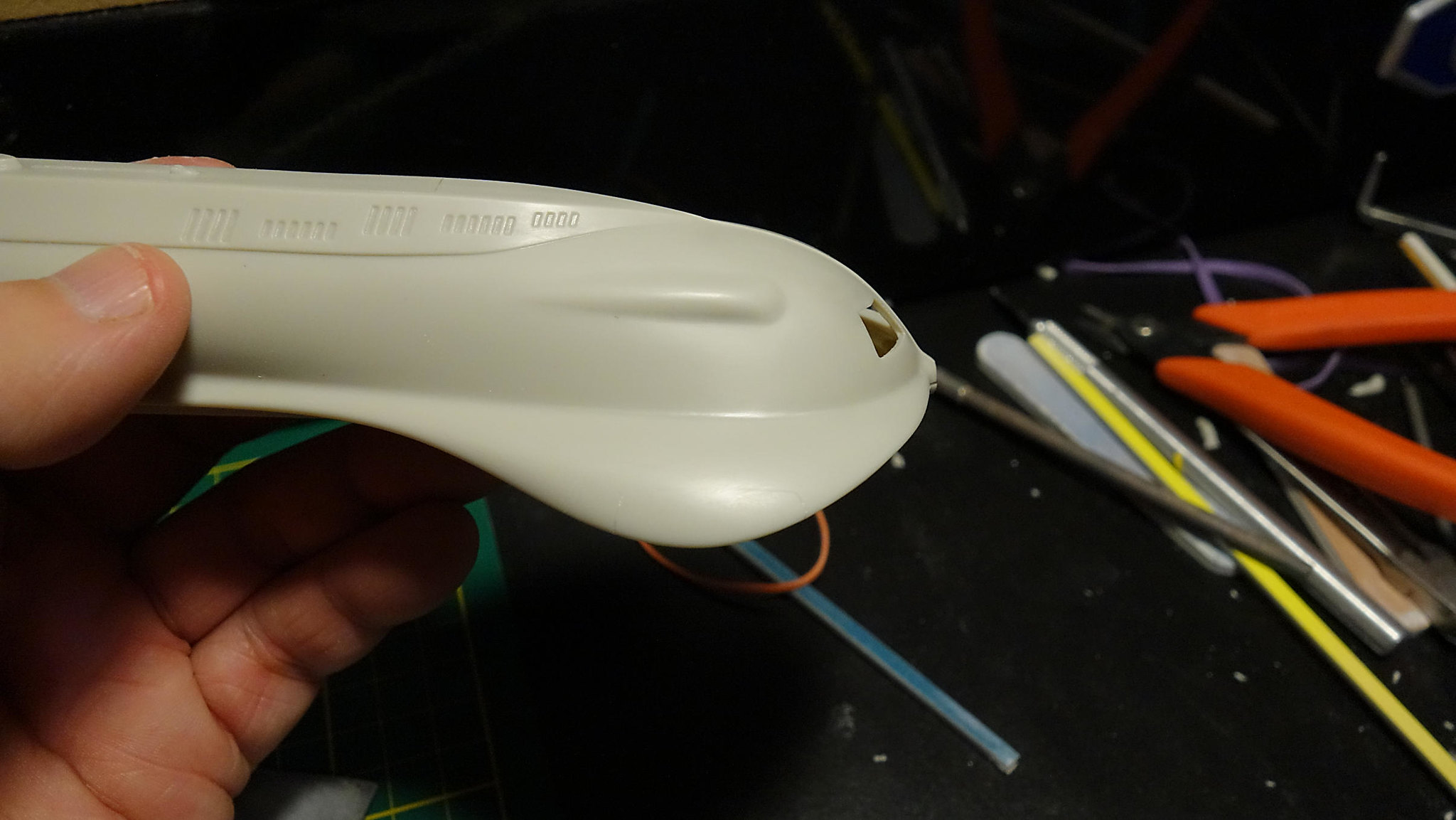
I fixed a defect at this location as well. There was a hole from where the plastic didn’t fully make it through the mold. I used CA to fill, build up, and shape it to what it should likely be.
What is next? I don’t know yet but I think part of the day I will start researching the interior lighting. I am quickly approaching the paint stage, and I will need to get the lighting sorted out.
Looking sharp. It would also be a good time to figure out how to mount it to a base.
For instance you might glue nuts in along the keel for screws.
Coming along good, Steve. Those darned simple-looking kits, eh?!
All fills and stuff look good. The main seam between the missile tube covers looks challenging indeed. I don’t know if I have 4 hours worth of patience for sanding so Bravo to you.
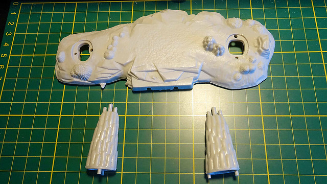
Thanks, and that is a good thought. What I had been thinking is to use parts of the stand that comes with the model. The keel already has holes molded into it for the stand. So, I could use the two coral looking pieces shown below, and cut them to the height that I need. Then maybe, hot glue the bottoms to the base. If I have a lot of room I could even incorporate the bigger piece for more stability. If you see anything that I may be missing, let me know.
Thanks again!
Yeah buddy… this ain’t no Tamiya kit! On these older kits a person spends most of their time just trying to bring it up to snuff. It is sad, but true. I’m good with that though. It gives me an opportunity to practice my puttying. [:P]
PS: It might have been faster if I used something other than CA. That is a big might.
A learning moment…
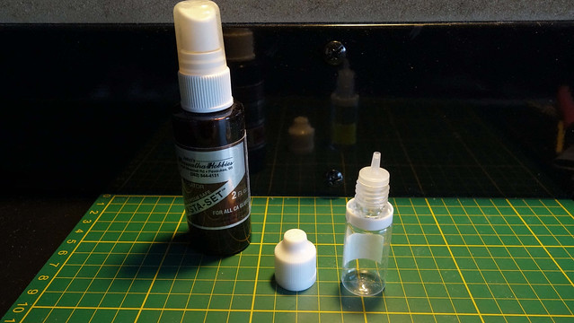
During my 4 hour filler marathon I had an oops that set me on a new path. I use a CA accelerator as part of my CA filler process, and the reason that I do is because it speeds the process up, and it takes the guesswork out of when I can start sanding. I can begin sanding as soon as I hit the CA with the accelerator. Anyway, the bottle that I have is a decent size and it is designed so that you spray the area being worked on. The problem with this is that it sprays in too large an area, and in too heavy a volume. It’s a waste of the product and a nuisance for cleanup. So, what I do is remove the spray head and use the siphon tube to drain some of the accelerator over the area that I am working on. This works pretty well, at least up until I knocked the bottle over. It was the sound of clug clug clug all over my work station. Do you know how Homer Simpson shrieks when he does something stupid? Well, that was me when this happened.
It is said that necessity is the mother of invention. I say, gosh darn right. I went to a surplus store and found this small applicator bottle. The benefit of using this bottle is twofold. The first is that it makes it pretty much spill proof. Secondly, the design allows me to apply the accelerator one drop at a time, and precisely where I want it. Why am I telling you all this? Eh, maybe it will help someone, and at the same time it is fun to share the stupid things that I do.
Back to the build…
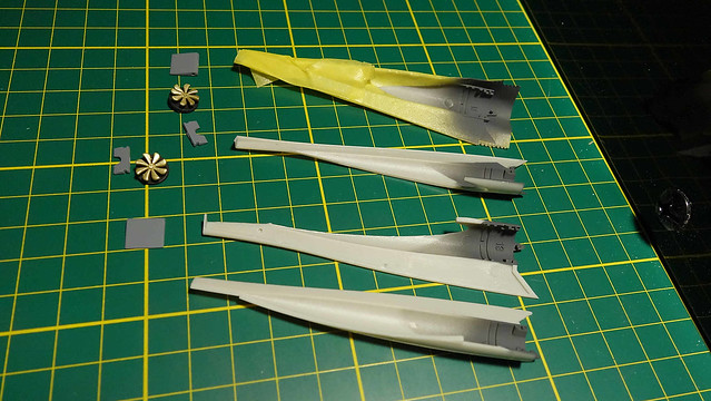
I am currently working on the propulsion tube assemblies. The components are de-sprued, sanded, washed, and just tonight painted. I will install them into the outer housings once the paint thoroughly dries. Then I will fill the joins and set the assemblies aside for final paint.
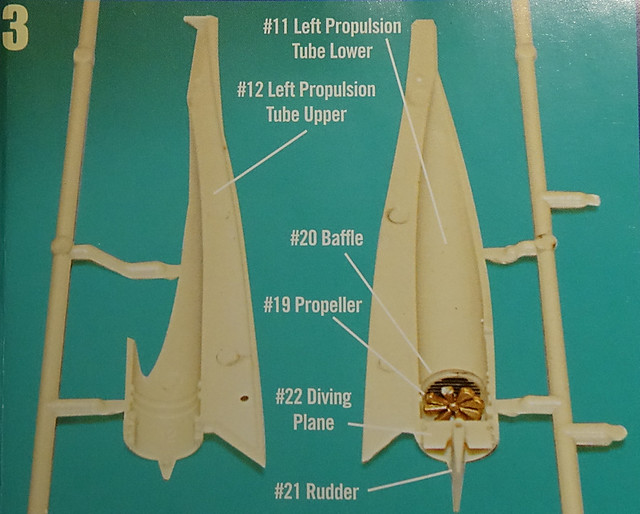
Below: the assembly as shown in the instructions.
Lastly, I am still researching the lighting and the base to build the sea-sculpt in. I have been looking at some shadow boxes as a possible platform to build the water on/in. I kind of like the idea of having the water enclosed in a frame and filled to the top.
More to come.
I mixed a darker shade of gray for the propulsion tube outlets. I thought it would be nice to add a little contrast to the assembly/model. After all, most of the model will be in one shade of gray. The instructions said to paint the props in brass; I went with it. The rest of it is in line with the instructions.
My recollection as a kid was that I had a terrible time assembling these. I seem to recall a fit issue with the baffles, and then there is a bit of a balancing act with the diving plane and rudder. I was pretty young then so maybe it was just me. We’ll see how this goes.
Building this kit is bringing back a lot of lost memories. I am still enjoying this very simple build. It’s a fun one.
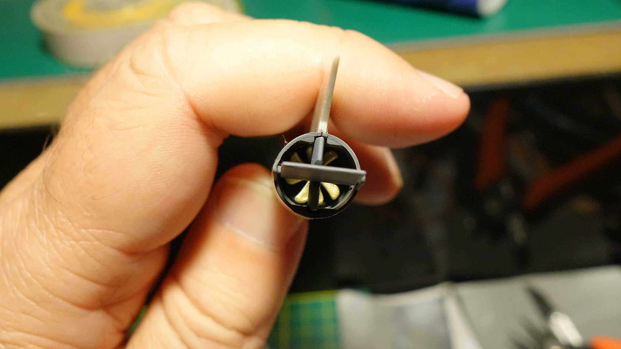
Well, the assembly went fine, but with one gripe. The biggest gripe that I have is that the baffles are amazingly undersized for the assembly. The end result is some major gaps between the baffle and the wall of the propulsion tubes. The good news is that you can’t see the gaps by looking.
The way to tackle this assembly is to position the baffle as best as you can, and then tack them in place with some CA. Moving outward then… I glued the diving plane into position. Lastly, you align the hole on the rudder to the pin on the PT housing, and then do the same on the other side using the other PT section. I did not glue these joins because they are tight enough on their own. Doing so leaves you with the ability to pivot the rudders after install. That is kind of cool. I should note that I installed the props to the baffles prior to all of this.
Lastly–I can see why that as a kid I had problems with this assembly. Building it this time around I have the benefit of an almost instant bond that CA provides. This really helped me with the assembly because with the loose fitting baffles and diving planes, they need to be secured really well before advancing to the next steps. Given my age at that time, and the natural impatience of being a kid, it was beyond me to wait the long hours of curing that tube glue requires.
What’s next? I need to fill the gaps on the PTs.
After completing one of the PTs last night, I felt like working on something different.
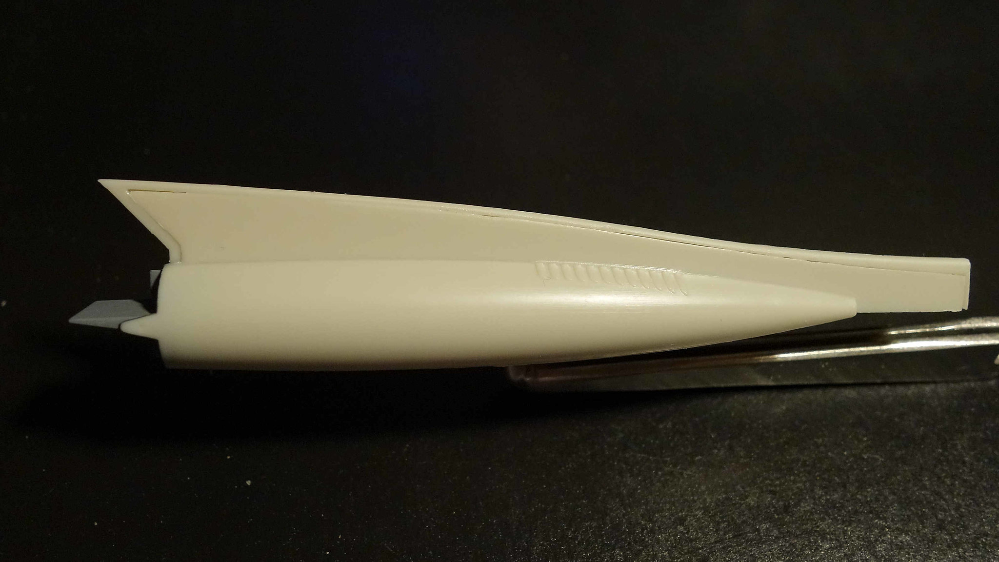
Below: There is one thing that has been nagging at me about this model, and that is the forward stabilizers. In my opinion, the recessed panel lines are massively exaggerated making the sub look toyish. To confirm my thinking I found some screenshots from the show. In every case I could not even see them. That is not to say that they were not there on the studio prop. I did find an artist’s rendition that had them, but the scale of the panel line is barely visible. So, armed with that, I set out to remove them entirely.
Below: CA magic is applied.
Speaking of CA, I am happy to report that my CA accelerator bottle is working excellent. I accidently knocked it over twice with no spills. Also, the amount of control that I gain by using this makes me feel like a surgeon. If anyone is interested, you can purchase them through the link below. Unfortunately, for on-line purchases, the min buy is 10. I am blessed to have a store nearby and I can buy as few as one. If anyone is interested, I can pop one in an envelope and then mail it to you. I figure $1.50 should cover my costs. PM me if interested.
https://www.sciplus.com/s/4?sStr=Bottle
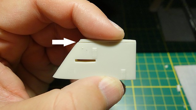
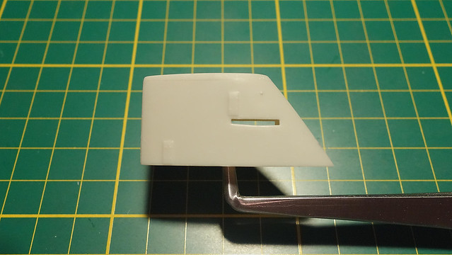
Below: I should have imaged this piece/fit showing what it looked like before I had worked on it. Needless to say, it needs work. I have more work to do but the majority of it will come later when I am ready to close it up. At that point, I will fill the gaps with CA and smooth things out.
All this work that I am doing is kind of a moot point because the sea sculpt will cover it. But, I’ll know it’s there, and it gives me a chance to practice my filling.
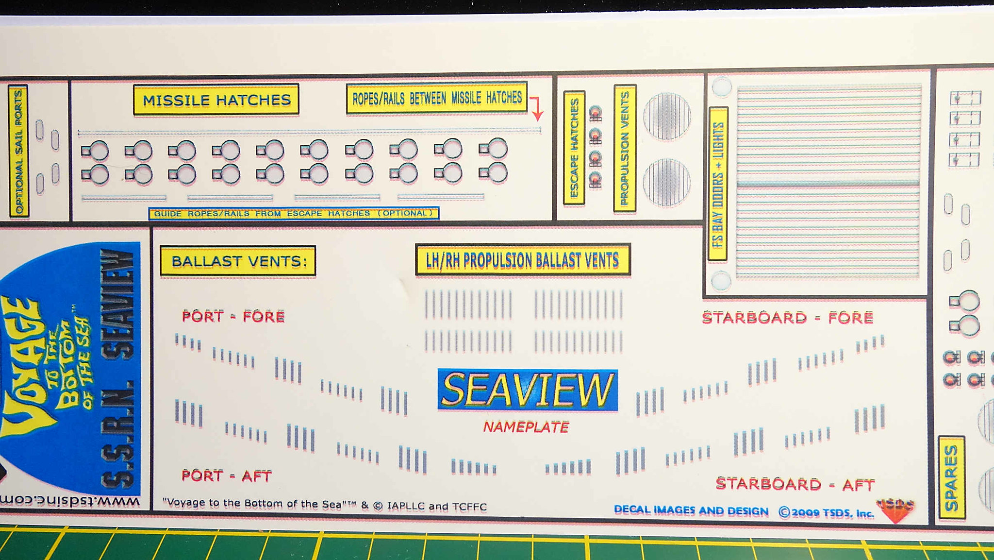
Below: Buyer beware. I found this aftermarket decal sheet and I decided to order it. I was hoping to use it for the ballast vents, and if I was lucky, maybe the missile hatches. Well, the quality of this thing is horrid. You be the judge. There is one other thing about this. The entire graphic is one decal. So that means, you’d have to trim everything out too. This is being returned.