Italeri PT-Boat Build Kicking Off

Paul,

I really like your build -and the way you have the model displayed really conveys a sense of motion without (and this is key on a model this size) taking up a square yard of display real estate!

Would you mind sharing some details on how you constructed the base??? I think I’d like to try something similar!

Also - what figures did you use…?? This is going to be my first real effort at putting figures on a model so I can use all the help/advice I can get in that regard!

John

Thanks, vector!

On the small parts/photoetch. I would have to say that the key is really learning how to manage/work with CA glue.

The biggest thing I’ve learned that has taken my building to a whole new level is really very simple: De-Bonder!

I put the parts on and then use de-bonder on a Q-Tip to clean up any undesired excess. On metal parts you can be as agressive as you want, but I have noticed that it will temporarily soften plastic to the point where you can leave fingerprints if you aggressively apply it.

On the other hand, the softening is only temporary and you can always clean things up with a light sanding afterwards if necessary!

John

Here’s my latest progress report:

I did some work on the hull and ran into some problems that most people probably won’t experience because they are no doubt much smarter than me!

First off: The hull chine comes in 6 pieces (3 per side) and fits in a groove molded into the hull (see picture below).

The problem I discovered was that there is a definite orientation to these pieces despite the fact that the middle and aft pieces seem to fit ok in multiple positions. Unfortunately I discovered this after glueing the port aft and middle sections. CA De-bonder to the rescue!

The correct way to do this is to fit the bow pieces first (as they have a very obvious “correct” orientation) and hold them in position with masking tape. Then put the rest of the chine on again holding in place with masking tape and then glue in place with CA glue. One other clue you’ll have is that the injector pin holes on the middle and aft chine sections should be facing the bottom of the hull.

If you look in the upper right hand side of the picture you’ll see one of the bilge drains and a red dot. The red dot is there because I managed to get some of the A+B putty I was using for the forward head on the outside of the hull and thought I would clean it off by sanding - which successfully removed the very faint position marks molded into the hull. I used my plans to reposition the bilge marks but if you build this kit let my mistake save you some work!

I added an electrical wire from the junction box to the torpedo controls:

To do it I used some small guage wire and drilled out the end of some small diameter plastic rod. I attached the end of the wire to the rod with CA glue, let it dry then cut the rod to the appropriate length to simulate an electrical plug. I then glued the plug to the junction box, let it dry, then routed the wire. After cutting the wire to the appropriate length a drop of CA glue finished the job!

I also did some work on the main superstucture assemblies:

Here is the bow section - not much special here except I’ve been removing seems and I’ve opened up the two forward windows to allow for the LionRoar PhotoEtch replacements.

Here is the day room assembly:

Finally here is the aft engine cover. Of particular note is the skylight on the cover. The kit has modeled this feature as a raised “bulge” that is incorrect - the prototype is simply a skylight similar to the others on the vessel. I reproduced this as best I could by cutting out the old light and making a new one out of plastic strip. The technique I used was to glue strips wider than necessary at right angles to one side of what would become the skylight and then use the “chopper” to cut them to identical lengths before gluing the other side. If you don’t do this you are challenging yourself to measure each one of these pieces to very close tolerances - and I can tell you that it is almost impossible to get it right that way as that is what I tried to do first!

I got the itch to do some more with photo-etch while all the previous work was drying - so I tried my hand at starting on one of the MK 50 Rocket Launchers. Before I get started I’d like to share a few photographs with you I took last winter while on a business trip to Seoul Korea. I had a half day on Saturday to use as I pleased and chose to visit the War Memorial Museum. They had lots of armor from the Korean conflict - and I found THIS!!!

As you can imagine I was ecstatic as I have no idea where you’ll find a real life example of one of these anywhere else!

Here are a few pictures of the LionRoar modified MK 50 mount next to the unmodified kit part.

The LR part is more accurate in several ways: The support plates for the mount are more scale and the actual mounting post is too far towards the center of the plate on the kit part. The LR additions fix both of these problems!

One thing I did notice though is that after you cut off the mounting tube it may be a bit short…I’ll see how this plays out as I assemble the rest of the weapon! I also plan on adding bolts/bolt heads to the supporting plate using plastic rod and my hex punch.

Well, that’s all for now!

Enjoy,

John

I was really plesed with how the mounting worked. I used 1/8th inch steel rod. I placed the hull directly on the wood base angled like i wanted and used an 1/8th inch bit to drill through the hull and into the wood about 1/4 inch. I then took a section of rod and inserted through the hull and seated it in the wood base. Now with the base fixed in one hole I did the second the same and put the rod in it as well. Then… you guessed it, I did the third. Now i had the three holes perfectly aligned. It fit just snug enough to tweak it around and get the right position. Marked and labeled each rod and then i was able to remove it all and proceed with finishing the hull and base. I loved the results.

Coming along nicely there and it looks really good fitted to the base at the correct angle.

Julian [tup]

I know these questions seem silly - but I don’t have a lot of experience with the “hardware” end of things…

What dimensions did you use for your base and where did you get the wood (and what kind of wood)? What stain did you use?

Where did you buy the 1/8 rod - can you get it at Home Depot?

I really like your base and I think I’m definitely going to try something similar!

John

The base is Oak. I bought it at Hom Depot. It’s 8" wide and I do not know how long. I marked it where it looked good. [:)] The steel rod you can get at HD but I got Mine at my LHS. I ended up staining it dark walnut. It may take some tweaking but I’m sure you will be pleased with the results. Good Luck and have fun.

I would also like to say that your work so far has been great. I had no good inside pics of this boat so i just closed it up. The insides look just great so far.

Thanks Paul!

I’m going to try to recreate what you did - I really like the base and the Lion Roar comes with a really neat base plate that will look great as well!

John

I’ve made some progress! I spent some time on the Mk 50 5" Rocket Launchers and here is the result:

A couple of comments on accuracy/construction:

  1. The Lion Roar Pedestals are more accurate than the kit version. The support plates are too thick in the kit (no surprise there), but more importantly the support tube is incorrectly located too far towards the center of the plate in the kit version.

  2. The Lion Roar tubes are nice - but the design includes two very visible horizontal support plates that do not appear to be in the launcher documentation that I have. On the other hand, these would be an absolute BEAR to put together without them, so I guess you pay your money and you take your chances! I like the final result!

  3. I added bolt heads to the support pedestal and hex nuts to various locations on the launcher itself using a Historex Hex Punch and plastic sprue.

  4. I added an electrical junction box and fire control cabling to each launcher - now all I need to do is find a picture that shows how this cabling went into the deck!

I’m starting on the Bofors gun next!

P.S. I found a really nice build article by Marco Bosco at http://www.kitsreview.com/modules/news/article.php?storyid=43

It’s a great article but there is a catch - it’s all in Italian! I’ve been using some of the web freeware translating tools and I think I’ll be able to muddle through!

That’s all for now?

John

[:O] I love the look of those brass tubes, very nicely put together

I finally made some progress! I’ve been studying a lot in my “free” time lately so I’ve not had as much time for the “important” stuff!

At any rate, here are some pictures of the 40mm Bofors with full Lion Roar photoetch treatment!

There were some real tricky areas on this part of the kit.

  1. Be very careful with the alignment of the weapon after you sand off the kit’s mounting areas…it’s very easy to get this wrong.

  2. If you are using the LR photoetch - be very thorough in your analysis of the instructions. There are several PAGES devoted to this one subassembly and if you get too carried away (like I did) with “assembly-itis” you might not wind up with the easiest assembly task. Specifically, I mounted the back rail before I realized that I had to put in all those photo-etch shell holders. I think it worked out just fine, and I may have “lucked out” assembly-wise - but if you are following me be careful and make your own choice on purpose!

  3. The elevation and rotation hand cranks were pretty difficult to get right. If I was doing it over again, I might consider just using the kit parts.

  4. I chose to use the kit lever on the aft starboard side of the gun as I think it probably duplicates the original better than the pe.

I’m darn happy with how this turned out - I just love the “glow” of all that brass - it’s going to be bittersweet to paint it all!

John

Sorry for the duplicate posts but I wanted to keep things going in this one and posted to the other by mistake!

Here is the work I’ve done on the 37mm bow cannon:

And here is some work I’ve done on the torpedoes:

I’m working on the launchers now and they are pretty complex in terms of part count - but I think it will be worth it! More pics soon I hope!!

jOHN

I like your Mark 50s and your cockpit area and the 40mm too. Is the ammo drum on the 37mm a little lopsided or is it just me?

Garth

Things were a little off - I tweaked the alignment and it looks a bit better!

:slight_smile:

John

Finally some progress! My son was assigned the “Visible Man” model as part of his Anatomy and Physiology class so I had a detour to get that done before I could work on the “fun” project!

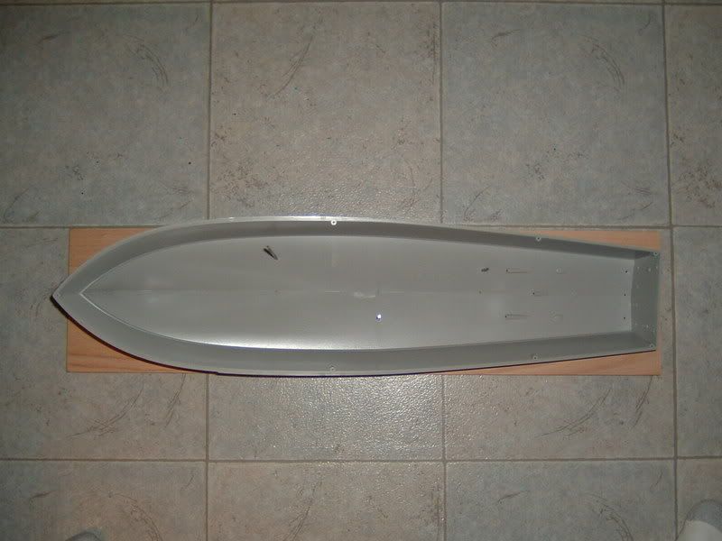
First off: As was previously included in this thread by one contributor but seems to have disappeared with the migration of finescale to the new format, I’ve built a display stand by purchasing an appropirate length of Oak siding from Home Depot and some 1/8" brass rod. I placed the hull over the board in approximately the correct position and drilled through the hull and just into the board using my Dremel tool for the aft centerline hole. I then used my Dremel drill press attachment to drill a 1/8" hole at the required location. I then ran the 1/8" rod through the hole and into the board and checked alignment before repeating the procedure for the forward centerline hole. I then repeated the procedure for the port and starboard supports.

Once all the holes were drilled and the rods were in place, I supported the hull using legos in what I hope will be interpreted as a high speed turn to port. Once the Hull was in position I mixed A+B putty and put it around the brass rod and let it dry. After drying, I used a Dremel cutting wheel to trim the brass rod.

I finished the oak board in Mahogony stain/varnnsh available from Home Depot.

Here is a picture of the brass rod in the hull supported by A+B putty:

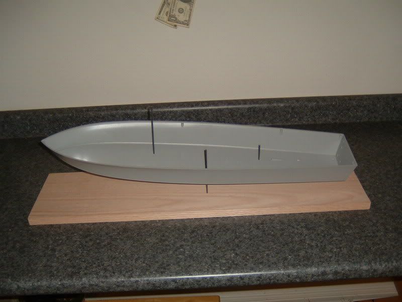
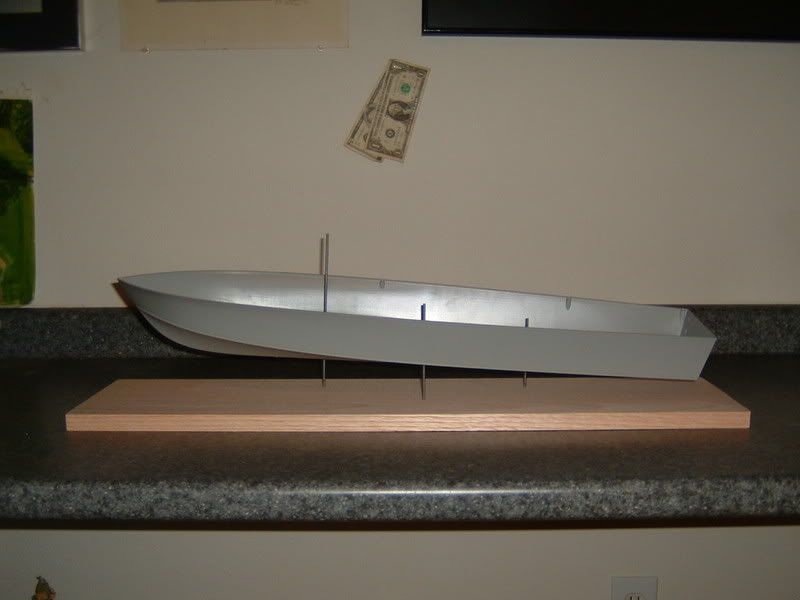
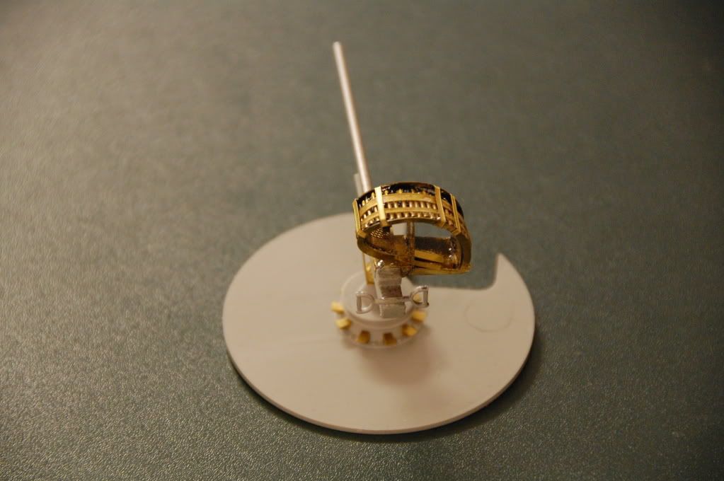
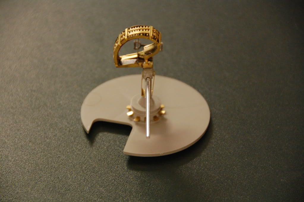
Here are pictures of the hull on the stand:

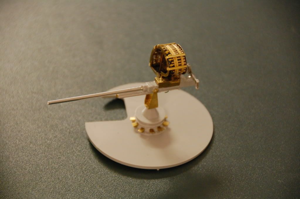
I also managed to complete one of the torpedo launchers - they are almost entirely rebuilt using the Lion Roar photo etch parts - 3 more to go!

I did a little painting on the forward interior hatch:

With the forward deck in place, it is going to be really hard to see even this high contrast detail - but I"m glad it will be there and I am confident that you’ll be able to tell something is down there as opposed to the generic black that I’m using elsewhere.

On last bit of progress…one of the kits shortcomings is the shape of the rudders. There are 3 rudders on the PT, and the prototypes had a much more “rounded” appearance than the kit rudders. You can see the difference here with the kit part laid in the proper position on the 1/35 plans by Al Ross:

I’m pretty new at scratch building things - so I’ll tell you my entire process including what didn’t work out as well as I’d hoped… The first thing I tried was making a photocopy of the kit part on the plans simlar to the image above and then trying to cut out a filler piece that matched the inside/outside edges of both the part and plans. That didn’t work out so well, because it is almost impossible to get the shapes exactly right.

I then took the kit part and traced the outline on plastic sheet with a pencil and cut along that line trying to get a serviceable edge to join to the kit part. Other than making sure the sheet was big enough to shape to the correct profile, I didn’t worry about the outer edge. I used Poly cement for the initial join, then beefed it up with gap filling CA glue. I then sanded the outer edge to the correct profile using a sanding stick after tracing the outer edge onto the part with a sharpie pen. Finally, I smoothed things up with some squadron white putty.

To make the part mold ready I added a metal tube extention to the rudder shaft and a toothpick with a notch in the end of it to the top of the rudder. You need to anticipate getting resin into the mold - therefore you need two holes - one to pour resin down and the other to let air out - with only one hole you will get big air bubbles when you try to replicate the part.

The mold is made using legos and clay. You make a 2-high lego box and layer the bottom half with modeling clay. You then embed the part in the clay and press “registration” holes in the clay with a pencil erasor. Mix and pour the rubber and you then have half of the mold. Remove the part and the clay, flip it over, and place it back in the lego box. Coat the rubber with release agent - making sure you have given the first batch enough time to completely harden, and then mix/pour the top half. Here is a picture of my part and the resulting mold:

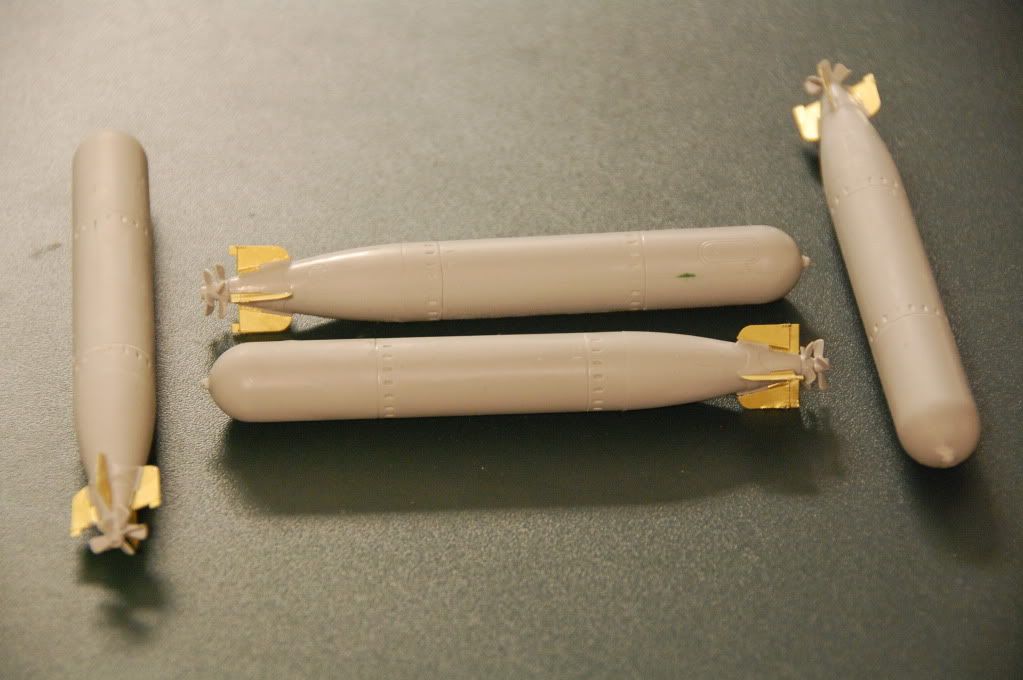
I had some cleanup to do - but in general I am very happy with the result - here are the replicated parts with the original kit part in the middle!

And more importantly: Here is how the revised part looks vs. the plans!

I think they are going to look great - and will be very noticeable on the finished model!!

John