Battleship New Jersey BB62 #3 Engine Room Start-to-Finish Build

Got your PM and when I finish this next edit I will get you a copy. And thanks for the nice remarks.

Well… printing the condensers has been a bit of a challenge. Yesterday’s print failed at 47%. We were out to dinner when the printer stopped. I rebooted it and it asked if I wanted to continue the paused print. I said “Yes”, it stated printing, but when I went down to see it, the print looked like this:

And PAF film at the resin vat’s bottom.

After popping the cured resin off the film, and futher inspection, it looked like a good time to change it out. I was at 47,000 layers when the job started. Changing out the film is not hard, but it is a bit time consuming. There are two layers of screws. First to fasten the entire frame into the vat body, and then 28 smaller screws to fasten the two halves of the sealing frame together. This view shows the new film in place and the film frame fastened into the vat frame.

Here’s the screws removed to release the old film.

The new film seemed to work and I finally got a perfect print of the TG condensers. It’s the weekend so I won’t be in the shop. I will clean these up on Monday. Here they are in the draining fixture. By letting the excess resin simply drain off greatly reduces the resin loading in the alcohol wash and saves expensive resin.

I also got the sub-frame and evaporators finish designed and built the first ladder on the specifics of this particular ladder based on the ladder detail drawings I have. They’re all different and all identified. I put in a smattering of floor gratings. I’m going to print a bunch of these so I’ll be able to put them where they do the most good. The evaporators are also supported on columns just as the turbogerators are.

1 Like

Just because it’s Saturday doesn’t mean that stuff isn’t geting done. Besides some exercising I worked on creating correctly sized and detailed ladders, started placing ladders and floor grating into perspective places. I also applied steam lines to the main condensate pump. Yesterday I added the steam lines to the turbogenerators. Gratings won’t hide too much detail, nor will the minimalist piping that I’m including. The grating supports on the lower level are pretty close to prototype. I haven’t decided how to support the upper gratings. I will have to study the drawings and photos to figure it all out.

NJ ERP More Gratings.png

The steam inlet to the pump has to come off the main steam pipe, but I’m really not sure how all these pipes do that. My photos are totally confusing, so I’m taking modeler’s license to put them where they make sense to me. I do know that every piece of equipment has a steam input and a discharge that has to go to a condenser. For the discharge of the pump, the only place to tie into a condenser was (I thought) would be into one of the TG condensers and ran a pipe to it.

NJ ERP Cond Pump Steam.png

Then…. while looking at this image and writing this post, I realized that there’s a pipe stub sticking out of the main condenser that—most likely—was actually the place where this condensate line would enter. So I re-routed the line to this stub and it makes a lot more sense. You’d be surprised how many insights I get when writing all this stuff.

NJ ERP Cond Pump Steam V2.png

Lots of things to print. I’ve started printing the piping. I have to design and print the two lubricant pumps (one electric and one steam turbine), one large and two small air ejectors that removed dissolved gases from condensate before it goes into the boilers as feedwater, and the electrical cabinets and two control panels. None of these are big or show stoppers.

2 Likes

Thanks gents!

I’m reprinting one of the TG condenser frames due to a leg breakage and the one that I had to glue on. It was time to just redo it. All it costs is some time and resin. Meanwhiile I fiddled with the opening in the condensers to accept the large exhaust flange. The hole needed to be englarged a bit so nothing had to be forced. Getting this all to fit together and stay together is not a given.

It was a gorgeous day here in Louisville topping out in the mid-70s (F) and with a slight breeze. I took advantage of this and started some of the solvent-based painting. I got the turbine rotors and MRG gears painting with Humbrel spray chrome. It’s a very nice, bright metallic paint. I also painted the bull gear. I was going to start doing all the primer painting of all the other parts now printed, but a lot of them had to be touched up with sanding and cleaning, and I was running out of time and didn’t want to rush it. I make bad mistakes when I rush. The gears look pretty good and will look even better when in the gear box. Speaking of which, I’m working on getting the main parts to fit better and preparing for the assembly screws before any painting.

I still find it hard to believe that I drew and printed those gears…

I spent the rest of the workshop time working over the piping and getting them converted for printing. I’ve also set up for printing of the “angle iron” frames that support the floor gratings. I’m printing a bunch of each type and size. I got the ladders ready for printing as well. Parts count is rising! I have to study how the upper floor gratings are supported. There is a mezanine level on the port side wall that holds all the electrical cabinets and the electrical distribution control panel. None of this is complicated, but it has a flooring frame and lots of gratings.

I’m holding off on designing the main control panel. In 1:48, my ability to do decal faces is difficult. I can produce them on clear background paper and paint the gauge faces white before application. That simplifies the process. And I just thought of it while writing the last sentence. I need Ryan to get me some good images of the panel that I can use.

4 Likes

Printing lots of stuff. Had a pipe print failure due to insufficient support strength. Will reprint with changes. Printed a gaggle of flooring frames and even more walkway gratings. When I decided to undertake this massive project, one of my main decision points was if I could print respeactable floor gratings. The new printer produced stunning gratings that eliminate the need to create these kinds of things using photoetched. They are ephemeral and very fragile, but when glued to the floor frames they will hold up nicely. I finished the turbogerator condensers with most of their piping. On the printer right now are all the ladders needed in this space. There are five different varieties.

First the condensers.

I pre-located the drill holes in the drawings and subsequent printings, so the holes just had to be opened up to 1/16". A piece of 1**/**16" brass tubing made a very secure connection with CA adhesive.

Here are the condensers with all minus two pipes.

I printed a bunch of single and double floor frames. There’s one leg that I designed without enough integration and it’s not very strong. I reinforced its interior with Bondic making it more secure.

I also have a ton of worthy floor gratings. Took close to an hour to carefully separate them from their support system. This new printer will reproduce just about anything.

Some of the bars are damaged on the edges, but they’re bigger than the frames. When trimmed they loo pretty darn good if I do say so myself. When painted oxide red they will be great.

And they look great (no pun intended) from above being almost transparent due to the thin bars.

​I’m designing the lube pumps. There are two: one electric powered that was installed in the 1980s refit, and the other steam turbine driven that appears to be the original design. When I dropped their foundations into the master drawing, I was concered that there seemed to be no room to move around them. I remember walking next to the pumps with lots of room. Did I make a scaling error?

Nope!

Based on this analysis, the configuration of the equipment in ER #2—the one open to the public—and ER #3 shows very little clearance around the pumps in the one I’m doing. It’s the position of the MRG in #2 driving an outboard properller shaft #4 and ER#3 driving an inboard shaft #2. Shafts are numnbered from startboard to port, whereas engine rooms are numbered from fore to aft. The drawing tells the story. Notice that the ladder to the upper lever is very tightly fitted, versus the wide-open-spaces in ER#2.

In this picture that Er#2 roominss is on full display. That space does not exist in ER #3. That old dude walking is me…

So I will be trued to the plans a shoehorn the pumps into their repestive spaces. Onward and upward.

1 Like

The ladders came out as nice as the gratings did… maybe better. Here’s some pictures that show. The stair railings are only 0.020" or about 1 scale inch. Actually scale! By not curing the resin more than 3 minutes and with my resin blend, the railings still have a lot of sprint to them. You can bump them without breakage.

​Below: this was before I did some very delicate sanding to remove the slight support nubs that remained.

This is the five step stair.

And I threw some grating next to the tgs just to see how it looked.

Gratings was one of the things I thought about when I decided to build this ridiculous project.

I’m continuing work on the lube pumps. Don’t have any good drawings of these so I’m working only from photos. Electric pump is one the left and steam turbine pump on right. Steam pump is OEM from 1943. Electric was swapped in 1980s refit. Steam piping is complex and I’m trying to interpret. Couldn’t get close to them in ER #3. Work platform grating is where the legs top out. The legs rest on the 3rd bottom (hold floor). Still have to fit them between the main reduction gear supports. Probably will need to modify.

This is what I’m talking about… it would be a bit easier if it wasn’t for all the insulation.

2 Likes

I’m just about finished designing the main air extactor. The first thing I had to do was learn what an air extractor is and why is it there. There are three of these in the engine room; a large Main Air Extractor (MAE) and two auxiliary air extractors. The main is pulling vacuum from the main condenser and the auxiliaries are pulling vacuum from the turbogenerators condensers. They look the same except for their size. For steam turbines to function effectively, the exhaust steam must be drawn out of the machine into vacuum. The steam is depleted to a point where it would lose all forward momentum without the vacuum. There is some negative pressure created just by condensing the volume of steam to water in the condenser, but it’s not enough since there is leakage in the system.

The main air extractor works on Benoulli’s principle that pressure on a surface is reduced inversely proportional to the speed of a gas over the surface. 600psi steam is applied to a venturi where the suction line is attached to the gases in the condenser further reducing its internal pressure. Very high vacuums can be drawn this way. The MAE outputs the extracted air to atmosphere and any condensed feedwater is fed back to the main condenser hot well. Further feedwater prep is done in the firerooms and is not part of the model. There is also condenser coolant water in and out that is used in the internal condensers in the MAE. It’s really a complicated piece of equipment.

I am totally guessing exactly where the piping goes for this thing. Here’s the a picture showing why that is.

Given that, here’s a rendering showing it in place on the upper level. I don’t have any detailed drawings about the MAE or its foundation. I have four images inclduing these two.

I’ve got requests into Ryan asking for more information about this. Regardless, I’ll do something respectable.

I printed the lube hand wheels separately and applied them with 0.025" phos-bronze wire. Look much better than the partially deforemed ones that were printed on the part.

I removed all the tall angle supports from the MRG frame to accept the smaller version that is now printed integral with the Lube Pumps. After prepaing the surfaces I used the rubber-infused CA to adhere the electic lube pump. The modified (fixed) steam lube pump will be printed along with the MAE today or tomorrow. The electric motor came out beautifully with the cooling ribs perfectly defined.

While the steam pump print has some errors there were some spectacular print features that blew me away! This is an extreme closeup of a spring that I downloaded from the SketchUp 3D Warehouse. I reduced its size, but did nothing else to it when I determined it was printable. It has some loops at the end.

Here it is on the pump.

And if you look closely, the printer reproduced those loops. This isn’t supposed to happen… or at least it didn’t happen with previous versions of the LCD resin printers. With the naked eye, those parts are tiny. They’re 0.010" or less.

I printed more ladders. I found that the short ones were also with full treads and I needed a ladder with 9 rungs.

Getting good at making ladders. Till next time…

1 Like

I got the aux air ejectors designed, but they’re kind of fictional. I have no drawings of them nor do images help very much. Here’s an image that “shows” the two aux air ejectors that produce vacuum for the turbo-generators. Can you see an air ejector hiding in that piping? I can’t. Therefore; I just shrunk the main ejector until it made a resonable size. Anyone visiting the engine rooms probably won’t see much of them either. They are on the right side of the image.

tempImage4KIXjK.png

I have the foundation drawings for the aux units. They are brackets that attach to the bulkhead wall with stiffening on the fire room #4 side. I drew them sort of correctly, albeit simpilified. That said, I don’t have any drawing of the units themselves or the foundation of the main air ejctor. If it goes straight down to the 3rd skin like some of the heavier gear does, it won’t work becasue they would pass through the end bell of the main condenser. I chose to bracket it also.

Screenshot 2025-03-27 at 1.02.22 PM.png

Here are the two unpiped aux air ejectors. They are fatter than the real ones.

Aux Air Extractor Supports.png

I’m running into a jam trying to get the clear acrylic bulkheads laser cut within a budget I can tolerate. I’m donating this model like the other two, and spending the best part of a year in its creation. As a result, I’m trying to mitigate out-of-pocket expenses as much as I can. That leads us to plan B; back to hand-cut styrene sheet. I’ve already bought the sheets for this eventuality and will make the end bulkheads and all the under-floor framing out of styrene. Styrene is much easier to glue togther (silver lining).

I’m calling this approach, “the Swiss Cheese cutaway method”. The stiffeners on the fire room sides will add structural integrity to make the bulkheds work. There would be part of the boiler supports on the other side. Stiffeners are mentioned on the plans.

Here’s the fore bulkhead:

Fore Bulkhead Design.png

And the aft bulkhead. It’s important that they support the propshaft pass thrus. The tongue sticking up is supporting the entry ladder. I think I’m going to make a bit of ceiling there to model the entry hatch into the engine room. It’s an important feature. There’s also a small hatch in the fore bulkhead to enter the #3 fire room.

Aft Bulkhead Design.png

I printed out full-size plans for all the styrene parts in prep to handcut them. I’m still waiting for another quote for laser cutting acrylic, but I’m not very optimistic about the outcome. I still have to design the control panels and electrical cabinets. After that paint and assembly will begin.

1 Like

I’ve piped the aux air ejectors. This is not prototypical, but it’s reasonably functional. This is just the primary lines. I’m not attempting to include any secondary lines. I may attempt to print this as a complete assembly… would help in alignment. Ryan gave his approval on the “Swiss Cheese” approach. I will have a lot of styrene cutting to do.

1 Like

While still doing more design, I started on the styrene parts. I printed full-size plans for all of the parts using PostRazr to help convert bigger-than-letter-sized drawings to mulitple page prints since my version of CorelDraw doesn’t play well with the latest version of Mac OS. I’d have to pay another $300 to upgrade CorelDraw… which I’m not going to do. You export the big drawing as PNG to PostRazr (free online app) then it converts it to a tiled PDF output that can be printed in mutiple, overlapping pages by Adobe Reader. Convuluted, but free.

I started cutting the pieces with the front bulkhead. Maybe I should have started with some of inner pieces to perfect the cutting… nope. I used the Lord Nelson method, “I went straight at em’”. Might have been a mistake. I mis-drilled one of the lightening holes in the lower frame portion. This will show!

I cut the holes for the prop shaft seals. These go in at an angle so a little siop in the fit is tolerable. To cut these I used my dividers-with-a-chisel-blade method, where I just twirl it around and score the plastic. I cut radial slots to the center and break out the piece leaving a reasonably-sized hole. Some light Dremel sanding work cleaned up rough edges. The shaft seals fit okay.

I used the same method for the steam pipe opening at the top. For the oval hole for the condenser inlet scoop I used the "drill-a-zillion-little-holes-around-the-perimeter method and used a #11 blade to cut between them, breaking out the center. Again, Dremel sanding finished it up. I chose to drill all the rest of the holes and radii. I didn’t have a plastic-ground drill of the right size so i had to grind one. I have a commercial plastic bit that I used as a guide. To drill soft plastic like styrene you need a sharper point angle. Standard drills are 118º and need to be something around 90º. Also the drills need less rake angle under the cutting lip. If you don’t do these things, the drills will tear and grab the plastic creating more of a mess than a hole. The grind worked.

I used a small pilot drill to locate the centers of the frame holes and drilled them all successfully except for the hole 3rd from the right in the picture. I am really annoyed by this! I so annoyed that I may plug it and re-drill. I’ll think about it. For all the rest of the holes in all the frames, I’m going to temporarily glue them together and drill as a batch including the back bulkhead. I’m also going to drill the upper end of the cross-lap slots instead of working about cutting a square edge. it won’t matter.

To cut the remaining free-form shapes i’m thinking about using a jig or jewelers saw. I did the first cuts by scribing with a #11 blade and breaking out the pieces, but occasionally the knife slipped and cut into good stock that will leave a mark requiring post-finishing. Using the saw would be more controllaable and leave smoother edges.

Meanwhile, I’m about to finish the last drawing challeges, including all the electrical, control panels and diamond plate flooring for the lower level. The diamond plate I drew for the 5" proiject, while scale-sized was too fine to see well in 1:48. I’m going to enlarge the bumps a bit and then print.

The complex nature of the project at this point is mind-blowing, even for me, and I’m the guy doing all the drawing. Notice the large column in the center of the image. That’s a prominent feature in the ER. It required me to change the routing of the main steam pipe to clear it. Also note that the upper mezanine platform is ready to receive the electrical equipment after I draw it.

All of the platforms and catwalks will require handrails before they’re fully done. I’m probably going to make them out of soldered phos-bronze wire to reduce opportunities for breakage. I’m still working out how all the floor panels will be supported, especially since there’s not a full bulkhead in the fore or aft from which to hang them.

I tried using the jewelers saw, but it wasn’t worth the trouble. Went back and did it by scoring the lines and snapping. Took my time and the results were good. I cleaned up the holes and curves with the Dremel with the smaller sanding drum, and did deburring and it’s ready for the slotting. I’m going to slot all the frames glued together so regardless of their specific precision to holding the lines, they will all be equal. I cut one mid-frame out of the 0.040" sheet, but stopped at that one. I was concerned about running out of the thicker stock for the rear bulkhead. I can get away with the 0.030" stock for the cross-frames.

NJ ERP Front BH done.jpg

I attached the Aft BH to the styrene and began cutting it out. This image shows closeup of how to do a scored diameter hole in styrene. After scoring with multiple passes with the dividiers, I scribed cross-line all the way through which provides a place to grab with some pliers to snap out the pieces. The hole requires a little sanding drum work to clean up the edges and do final fit on the shaft seal.

The print of the Main Air Extractor came out beautifully. The pictue shows two of them. I only need one. One is a better than other slightly, and I’ll use that and put the other in the surplus pile.

NJ ERP Main Air Ejecctor Prints.jpg

In the same run I printed the four remaining tubes from the TG condenser to the heat exchanger. There were two on each TG and are slightly different. The valve bodies and their handles came out really nicely.

NJ ERP TG Piping done.jpg

I re-drew and improved the diamond plate I used for the 5". This was originally downloaded from the SketchUp 3D Warehouse. The original size of bumps was too big for 1:48 and I shrunk them. For this application I shrunk them a bit too small. That said, the orginal artist didn’t group or convert the bumps to Components. With SU Components, if I change the configuration of one bump, all of the bumps change regardless of where they are or how many plates were drawn. I’m printing the flooring in 2’ X 4’ pieces. I made them pretty thin and adding some cross reinforcement to help mitigate warping. I’m printing out 20 of them and it’s going on the Machine tomorrow.

NJ ERP Diamond Plate.png

1 Like

The amount of detail you’re putting into this project is insane. :open_mouth:
It’s just mind boggling.

Thank you! It’s not that each piece is super-detailed, but the collective works is freaking me out. All during the design process I’m building it in my head, and attempting to make sure that I can actually get it together. By the end of next week, all the parts will be printed, plus any sheet stock parts will be done also.

I just set up the redesigned main steam pipe for printing. All the 3D printed girders are in the Machine waiting for printing. My older machines had no storage. All the files had to be loaded via memory stick. Now I send them via WiFi and the Machine has its own file register where you can store or delete. It has a large storage capacity. I tend to remove them when I’m fairly sure a reprint won’t be necessary. It makes it easier to select the files in the machine for printing since it only shows four files in each page in its LCD display screen.

You can also start prints remotely, but I want to be there watching it start. For example: today, it went into a “Auto-Leveling” fault. If I wasn’t there, it would have sat for a long time not printing. Rebooted the Machine by cycling the power switch and it printed successfully.

1 Like

So I’m curious to ask, After you finish the engine room, what other future Iowa class battleship project will you do next?

You had to ask? At this point, I really want to finish this in the way I envision it. I wake up everyday working through the next things to consider. For example, this morning I was working through how I want to support the 2nd level grating in the from where the fore bulkhead doesn’t provide much in the way of surface area to tie in any bracing.

I’m thinking of maybe doing the steering gear. This isn’t on any tour itinerary, it’s way back in the stern where things get pretty narrow and it’s interesting. The other thought is either the fore or aft emergency generating rooms. They each have a 2,500KVA ALCo diesel generator and some other equipment. The aft room is more interesting since it spans side-to-side AND has all four propeller shafts passing through. It’s the only place in the ship where these are observable. I already have a terrific and printed ALCo engine of the same size, so it wouldn’t be too big a leap to do the space. Much less onerous that ER #3.

This model was created when I first got into 3D printing. With my increased drawing skills and the advanced printing capabliiites the model should even be better.

Now onto today’s work…

The Steam powered lube pump printed correctly this time, but I broke a pipe in cleanup. Picture will come after I fix it. I also got good prints on the aux air ejectors and the 9 step ladder needed for the entry stairs that come down from Broadway into the engine room.

I got the aft bulkhead and finished up ready for drilling. Unlike the fore BH, I held off drilling this and waited until all the frames so I could temporarily glue them all togther. Using the #11 to scribe all the curves really worked out well in the end. Had to change blades frequently.

I then cut the individual frames out. I used MicroMark pressure sensitive adhesive.to temporarily hold the patterns to the styrene. Occasionally, some cement stayed behind that was easily removed with Goo Gone.

I did not drill or slot any of them.

I then temporarily glued the stack to the aft BH in readiness for drilling all at the same time.

Before gluing the stack to the BH, I clamped them together and trued up the ends so they were all the same size on the 1" belt sander. I used little dolleps of Testor’s tube cement to hold the stack together. The holes were located on the BH with a smalll 1/16" drill that will center the big drill. I wish I hadn’t drilled the first BH yesterday. After I drill these, I will cut out the cross frames and do the same thing to them. I will cut all the slots while the frames are still stacked guarenteeing that all them are in the same place. Actually, since the floors will cover all but the outer edges of all this framing, I really don’t need to include all the cross-frames. I probaly will use them because, I’m a) going to cut them anyway, and b) the entire model is being fastened to this floor (as in the real ship) and having it solid and stable will not hurt. It will not, however, have to protect against topedo attack.

Started drawing the electrical equipment on the upper mezzanine deck. I finished the lighting tranformers that have louvered surfaces. Had to figure a way to draw reasonable louvers and think I got it.

I’m now drawing the electrical console. I have a good image of it, but not it’s sizes.

2 Likes

Here’s the “better” steam-driven lube pump. It’s not attached yet to the MRG foundation, just sitting there being photographed.

I still have put on it’s valve handwheel.

I drew the electrical distribution console. It’s ready to go to the slicer and then printing. I detaled all those little handles with the hope that they’ll print. With the recent success making tiny detais, they may just work out. As for the gauge dials… making 1:48 individual gauge face decals using inkjet decal paper has not worked out so well. The decal print is over-coated with some form of laquer to keep the water-soluble ink from running, but with samll decals, it happens anyway and the resolution gets destroyed. I will try. Ryan’s going to get me some good images of them.

Another view as if you were standing next to one of the turbo-generators.

Now for some more sobering stuff. I may be a fabulous, amazing modeler, but I can still screw up. Today I did.

I was so excited about getting the stack drilling of all the frames done, that I drilled the first two large holes in the entirely wrong place. I had drilled 1/16" holes at the ends of each of the slot positions and drilled the same as pilot holes for the big holes down lower. I drilled the two smaller holes on the extended slots at each end and then proceeded to drill the big holes in the tiny hole at the top of the first two slots, completely screwing up all the pieces in the entire stack. This error will not be seen in any but the two end bulkheads, but that’s bad enough.

I have two choices to fix… well actually three. I can fill the two errant holes in the bulkheads and with putty and craftiness, make them invisible. Or I can add one more correctly drilled non-bulkhead frame one bay in from of each end, showing a bit of the 3rd skin in each fire room space. Lastly, I could remake the bulkheads. The problem with #3 is I don’t have enough 0.040" stock left to make them and it’s expensive. I also don’t relish doing all that handwork needed to create them. I’m going to go for the patch first. If it works, I’m done. If it doesn’t I can go to Plan B and still make a respectable model. Choice 3 would be the last resort. Unlike remaking 3D printed parts where the Machine does most of the heavy lifting, doing hand-crafted parts over involves labor and I’m basically lazy.

1 Like

One thought I had, watching Ryan discuss such things, would be a section of the armored conning tower. The mass and thickness of that beast are hard to appreciate as a structure of the ship.

The conning tower could be done. Just seeing you put it in writing got my brain thinking about it.

Design work and printing continue. I’m almost at the end of the design phase. I’m kind of in the punch list arena now.

Work also continues on cutting the main framing that supports the whole thing. I went the “patching route” in plugging the errant holes in the fore bulkhead.

I filled them with Tamiya filler and will sand the first coat on Monday. Today’s my wife’s 80 birthday (I married an older women since my 80th is at the end of July) and promised I wouldn’t be in the shop today. The rest of the filler is patching the deepest surface scratches that resulted from over-aggressive sanding of plastic cement remnants that I used to hold the stack of frames together for cutting and drilling. I was amazed at just how difficult it was to slice them apart. I’m going to try a different method to do the same on all the cross longitudinal frames. I’m also not going to attempt to cut the slots by sawing. They just wavered too much. I’m having to recut them all with a #11 blade anyway, might as well cut them that way from the start. And I’m using a square to keep them nice and vertical.

The evaporators are printed and trimmed waiting, along with a ton more stuff, for some paint. I printed them hollowed out to reduce the resin quantity. I also included plugs left over from the hole-drilling task in the slicer. The plugs are a press-fit back in the holes and needing no glue. A quick sanding and the holes disappear. I use a large syringe to wash the resin out of the interiors with IPA.

Front view. I chose to simplify the plumbing on these, since I couldn’t make any sense of it. Ryan thinks they look great.

The entry catwalk is hung from the ceiling! It is not fastened to the main reduction gear that lies below. To replicate this, I’m creating a faux ceiling to support it. It will also support the entry hatch which is a feature I didn’t want to leave out (not yet designed). All of these frames are sliced and ready to print. None of the framing is a 1:1 replication and asserts a lot of “modele’s license”. The ceiling structure is more varied than how I’m depicting it, but viewers will understand. I taking advantage of the accurate main support pole in holding up the ceiling structure.

I also lined out the flooring supports for the main control board and the main air ejectors. Both of these are at the fore end of the engine room. Had to fuss a lot to get the support poles to clear all the apparatus below. Again, the flooring is not truly accurate with much of the support would hung on the cutaway fore bulkhed. This is the Air Ejector flooring bracing. Also note the added support on the flooring system running into the picture that holding up the catwalks next to the turbogenerators and electrical decking.

And here’s the port side floor system.

Lastly, here is the flooring system and electrical console on the slicer and ready for print. This file and the other floor bracing file has been transmitted to the printer and will be print next week. The only reason the main control board’s not ready for print is lack of information. I’m waiting on Ryan to send more pictures of it. It such an important feature that I want to make it right. I’m hoping that all the switches and levers on the electrical console print correctly.

I’ve ordered and received most of the electrical materials for the lighting. I’m using surface mount LEDs again, but in this installation, I’ve gone to cool white to replicate the florescent lighting used in the 1:1 space. I was able to get 200 LED chips for $6.35 plus KY Sales tax from Amazon. That’s $.03 a piece. Ridiculous! And they are very, very bright. I redesigned the electrical console with space for the LEDs and their wiring. Lighting is going to fun and challenging. It’s also going to add life to all the underneath details.

4 Likes

Missed yesterday’s post so today will be a twofer.

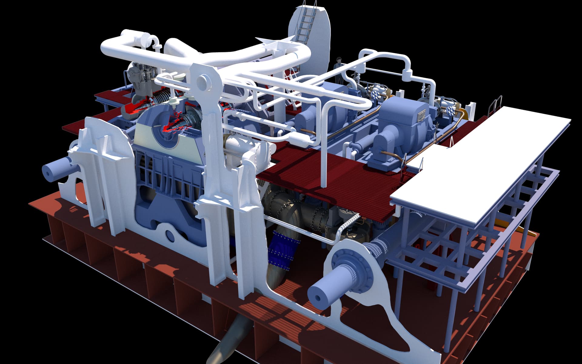
First up… thought it would interesting to see the vast number of parts already created for this project. We’re at the 95% level. I finished printing the smaller flooring frames and they’re waiting for trimming and sanding. I’ve also uploaded the file to print the remaining large floor frames. I’ve almsot finished drawing the various electrical cabinets, and Ryan has promised that he’ll take pictures of the main gauge board, which is the last piece to be finished. In those plastic boxes are all the floor gratings ladders and diamond plate pieces. All of this and no instructions! I’ve received all the electrical materials and am going to do some experimentation of soldering on copper foil attached to resin. Resin doesn’t melt per ce, but it can burn. If I can it would simplify attaching the surface mount LEDs. The large curvy pipe at the top is the new main steam pipe that has clearance built in to clear that large central pole (resembles a rocket in the foreground).

I printed the tiny hand wheels for the auxiliary air ejectors. I chose to mount them with 0.015" phos-bronze wire. I had to drill the parts with a 0.016" carbide bit. I got through almost all of them before breaking one. I attmpted to attach the even tinier smaller valve wheel using wire, but it proved ridiculous. I ended up putting them on with CA.

First image shows the valve hand wheel attached to the wire. Note the fine-tipped tweezers for scale.

And the finished parts: Pins are also installed in the pipe ends to faciliate gettimg them attached to the ma

I took some time off to rebuild additional lighting on my workbench. I had two of these puck lights left over from an under-cabinet project and used them for a couple of years. The voltage adjuster died rendering them dead. Another under-cabinet job gave me two more surplus LEDs pucks that I added to the one remaining. They’re 12vdc units and require no current management circuits. They just need a 12vdc power sorce. I needed another LED power supply for the engine room project so I bought two. I wired them up in parallel and added a toggle switch to activate them. Lots of needed light.

The circuitry isn’t pretty, but it’s solid and safe. That circuit strip needs some craft work to parallel the contacts, but jumpering them. The strips came from when I built my first railroad at our house in Düsseldorf, which explains why their “Euro-style”. I used them all over my model railroad and I’m finally running out them. When I decided to build my railroad in our German house, the head of the technical training department at Henkel provided me with an enormous amount of electrical hardware to make it all happen. It was when I learned about crimped ferrules on the ends of wires that are used along with these knds of terminals.

I printed the electrical control panel in the same run with the miscellaneous floor frames. The frames came out perfectly, but the panel was a failure.

The failure was not the printer’s fault. It was the draftsman… me. The drawing was flawed. There was a layer underneath the slant panels. The printer/slicer was confused by this inner layer and tried printing both. You can see this inner panel in the centeral area where another slant panel was supposed to go. I went back and fixed all the drawing errors. I printed it again solo, and the results are perfect. It’s draining on the printer and I’ll finish it up tomorrow. While it’s hard to see with all that excess resin covering it, the control knobs and switches did resolve.

Back to the main floor framing. Oh boy! I wish I could have had it all laser cut. It’s been well over a week and I’m still cutting away. I keep refining the process, but it’s a lot of heavy duty hand work.

After scribing and snapping all the long cuts, I used the Northwest Short Line Duplicutter 2 to gang scribe the cross-cut length.

To make the stack of the fore and aft beams, I used Scotch Double-sided “permanent” tape. It held the stack well enought and came off with no residue or sanding. Using plastic cement was more trouble than it worked.

I used a prick punch to locate all the holes and then pilot drilled the with 1/16". it was a bit too small for the big holes, but was perfect for the tops of the cross-lap cuts.

The big drill was okay… just okay. It wandered on a couple of holes meaning the some of the slots are not parallel to the part edges. Annoying? Yes! Show stopper? No! It’s all at the very bottom of the model and recessed from view. Won’t be seen much except by me. These holes drilled much better than the ones I did on the abaft ship frames. Part of that was due to holding the stack more firmly with a drill press clamp in additionl to my fingers.

I started cutting the scrap between the holes with the #11. I didn’t like how it performed. I switched to a single-edged razor to start the cuts. Worked better, but still not so hot. Finally I used my 90º corner chisel. This worked well. I don’t have any straight wood chisels. A 1/4" inch chisel would have been perfect.

I started doing trial fits with satisfactory results. There is another, 2nd skin mid-point in the framing. I’m going to add this only in the outer spaces since the inner ones would be invisible. The triple bottom was only used under the hull areas included in the armored citidel.

You are now all up to date.

2 Likes

The farther you get on this project, the more in awe I become. The magnitude of this undertaking is pretty much beyond anything I’ve ever imagined to do.

Considering that you are doing all the design, testing, printing, construction and finishing yourself is just mind boggling.

Just getting to where you are now is quite an accomplishment of which you should be proud. I can’t wait to see it when all done and hope to be able to see it in person sometime in the future.

Thanks for your kind thoughts. Each of these three projects all began with my thought of “Can I build that? How the heck can I build that??” I’ve developed a hobby ethos that each major project has to exceed the previous one in challenging my skills and know how. This one is not diappointing. It’s kind of a corelary to the famous quote by one of the Apollo crew, when asked about what does it feel like sitting on top of a Saturn 5 and he responded, “Like sitting on 5 million parts all built by the lowest bidder!” That sums up how I feel when I look at that table full of an ever-increasing pile of parts that have to become something more organized.

The electrical control panel exceeded my expectations. The elevated switches on the panel resolved with the levers in the various positions. Now all I have to do is paint the darn thing which could be a lot of fun (or not). The problems were entirely with the drawing. Fix the drawing… fix the part. As close as I could tell from the photographs, the controls are as they are on the real thing, even to their disposition.

​Work continues slowly on the under-framing. I keep developing better techniques. By the time I finish all of them I’ll have it all figured out. I did find a chisel narrow enough to chip out the material between the circles. Even with that, I had to refine how I was chipping it out. Instead of making three separate hacks at it, I found that if I slid the blade down a pre-scribed line (from a #11 blade and straight edge), the removed part had cleaner edges and leaving me with much less cleanup of the openings.

​While assembling the array for trial I realized an error was cropping up. The abaft main frames taper from the middle to the edges as the real floor does to let any water to flow towards the bilge wells at the outer corners and be pumped overboard. I, foolishly, wanted to faithfully represent this slant and built it into all of the cross-frames. That meant that all the fore and aft frames, depending on their location, would have differing heights. I built this into the patterns. But… I chose to cut them all from one template meaning they were all the same height. My mom used to say that "G_d protects fools, drunks and little children. In this case he protected the fool. Luckily, the template I chose was the tall middle one. At least I could remove the excess stock on the ones that are shorter out at the edge. It could have happened in reverse and I would have all the middle floors not reaching the tops of the main frames. As i progressed today, I took individual caliper readings and used the digital caliper as a height gauge scribing the correct height so I could shave off the excess.

​Putting the frames together was a little like herding cats, so I decided to tack glue some selected joints to stabilize it. One of them was on the “front” bulkhead. Later, as I added more fore and aft frames and then more main frames I found that I had hung the rear bulkhead where the front should go. Again, lucky that I only had one flimsy glue joint to break to make the exchange. I’m glad I’m doing all these trial fits.

Here it is with correct rear frame at the rear. It’s going to be a challenge to ensure everything is square. Also, liquid cement is not sufficient to hold the cross laps due to their slop. I will go back and use tube cemnet after everything is tacked in place. The flooring itsellf will be 0.030" styrene sheeting and that will made the whole thing very strong.

We’re heading out of town on Thursday so reports will have to wait until next week.

2 Likes