#100 Tristar Pz 38(t) B COMPLETE PICS P.10 10-24-09

Dear Bill,

As always your build log is so full off new ideas and inspiration it is almost impossible to just sit and watch[bow]

I have a couple of T38’s in the stash and you just gave me the necessary kick in the but to start doing them!

How are the Lion Marc machine guns BTW?

Thank You for sharing!

Best Regards
Svenne

Thanks Svenne! Glad to hear it’s inspiring you to work on your 38ts, can’t ever have too many of them going I say! [;)] This isn’t the first time I’ve used the LionMarc MGs and they are far and away the best AM barrels on the market IMHO for the 38ts. They include pre-formed brass trays as well as separate pre-formed PE sights and are little gems all by themselves. To use them on the Tristar kits does require a bit of modification since the mount pin on the base is too long, I just trim it down and then glue into place.

I’m off to dinner with my wife but as soon as we get back I’ll have another update with pics so you can see what the LMs look like. [;)]

This weekend was yet another highly productive effort so apologies in advance for the high number of pics in this update! Last time I said I was done with the details but that wasn’t quite true…I still needed to install the turret ammo bins in the rear and on the roof. The fit tolerances here are very tight so I used several small strips of masking tape to hold the turret sides and rear together so I could get the placement correct. There is supposed to be a small tool case that goes between the tray box in the middle and the ammo bin on the right but there isn’t enough space in the whole turret rear to make this work. Add to this the fact that the tool case in the Interior set is molded too tall and it got left off. A shame because it was a nice detail to have. The ammo bins were glued in place with CA gel to round out things here.

Now came the moment of truth…the creation of the cut-away sections. I gave this a lot of careful thought and opted to go with a method I’ve used before for smaller similar sections. The method is simple…perforate the sections needing to be removed using a micro drill bit and then cut through the perforations with a razor saw to remove the large chunks. Then the edges need to be smoothed out with a #11 blade and then sanded down where necessary to get a smooth edge. This method was applied to the turret sides, the hull roof, and the engine compartment covers. This effort took almost the full day yesterday to get it done but was worth it.

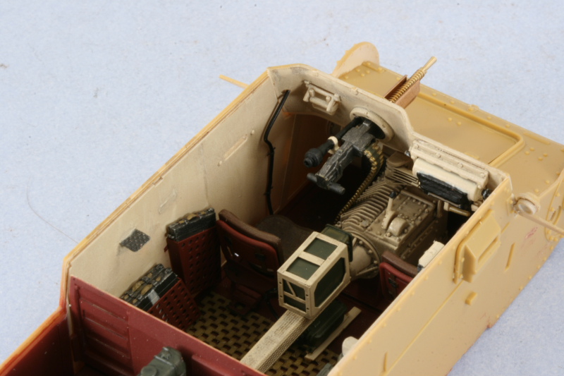
With that out of the way, it was time to finalize the assembly of the interior on both the lower hull and turret. First up was the installation of the superstructure front plate. I added the hull MG, replacing the kit exterior barrel and tray with the ones from Lion Marc. The Lion Marc set includes pre-formed brass trays and gun sights but the gun sight is very fragile/tiny, so I left that off until later to avoid the possibility of losing it. I drilled out the eyepiece for the sight with a pin vise and added an ammo belt courtesy of a left over item from a DML kit in the spares bin. The ammo belt was trimmed for length and bent to shape to fit the confines of the compartment before getting detailed and installed.

I also completed the wiring for the radio antenna. The length of solder I’d installed earlier was trimmed down to the desired length and a couple of small retaining brackets added using the flexible PE attachments from an old Eduard PE set cut to size and bent to shape with a piece of solder and tweezers. The brackets were then glued in place with small dots of CA gel to hold the cable in place.

The rear engine deck was added next, using careful applications of liquid glue and finger pressure to get a solid join all around. I did have to trim down slightly one of the ridges on the radiator that mates up with the air intake vent for everything to sit properly. The hull roof was then added in the same fashion and then set off to the side to allow the glue to dry.

The turret coaxial MG was added to go with the main gun, receiving the same type of detailing as with the hull MG. The only difference here is I opted for a shorter belt due to space constraints and to avoid the belt hanging down into the hull and potentially snagging on items there.

The Lion Marc barrel and tray were added to the exterior and the assembly work begun on the turret. I added the sides first followed by the rear plate and finally the front plate. The Tristar instructions indicate that you should have the turret roof in place before adding the front plate but this is virtually impossible to do because of the dimensions on the spent shell basket and the narrow confines of the turret itself. I learned that lesson when I built the Tristar E/F so was already aware of the pitfall.

The turret roof was added and carefully mated up with all the different surfaces using liquid glue, patience, and finger pressure. Some small amounts of putty were needed on the turret underside where the side panels meet up with the bottom but otherwise the overall fit was good. I also added the commander’s periscope and the rain guard over the gunner’s sight.

A test fit with the hull showed everything lining up perfectly.

Now I could finally go back to the “normal” order of construction on the exterior and the first order of business was the suspension. These were assembled according to the directions in Step 1 and added to the lower hull. I left the swing arms and springs fully workable until I added the wheels to be sure I could achieve a level fit. The sprocket housings were also installed along with the return roller mounts although I left off the rubber portions of the rollers for the time being to make it easier to paint and detail separately.

I also removed all the road wheels and cleaned up the mold seams on the separate tires with a sanding stick. The sprockets were assembled along with the idlers with the idlers getting the added bonus of their mount arms installed so they can remain movable when it comes time to add the tracks.

And last, but not least, the road wheels were installed to the suspension arms and the arms then glued to the spring bundles to insure the suspension sat level. The sprockets and idlers were dry fit to insure everything lined up ok. I also filled in the mounts for the front wheel bump stops with putty and sanded it smooth as these weren’t present on the Ausf B. Tristar incorrectly carried this over from the later Ausf 38ts that they’ve also molded but they weren’t fitted until the Ausf C. A small accuracy issue but one easily dealt with. I also puttied in the small mount holes for the shovel and pick-axe since the vehicle I’m depicting will have the stowage box mounted on that fender instead. This is an option that Tristar provides in the kit but they never tell you to fill the mount holes if opting for that particular configuration.

Next up will be the fenders and the remaining exterior details and then it will be on to paint!

Ah finally the long awaited update. Very brave of you Bill, to cut up the turret and roof plate after building and painting that interior.[bow][bow] Man this is going to be one gorgious model when the rest is done, I can’t wait.

Rob

[:O]

You are a far braver man than I am, Bill. Cutting away the hull like that takes some serious… well, you know [:I]

I’m lovin’ the work. Like I said I was going to do, I scored the interior and another 38(t) kit this past weekend at AMPSEast, so your build is going to be a great tool for me.

One question - did the ammo belts for the MGs come with the interior set or with the AM barrels that you got?

Bill does your wife know that you’re having a love afair with a 38 because this is pure sex.[XX]

Tony the Mutt

Great cutaways Bill. She’s looking fit for the #100.

Paging Doctor Bill!!! The surgeon like way you cut in the hatches was great. Everthing else is moving along nicely

Now all you need is a light inside to make viewing easy! [:O]…OK, I will let off this time!

Rounds Complete!!

Truely excellent work Bill. Everything is crisp and perfect.

Maybe you should cut away some of the turret roof panels to let in more light?

Wow…fine work w/ the cut-aways…this is very worthy work of your 100th…too cool…

Thanks Rob! It was tough putting it under the knife…I even used a sharpie to mark out some of the points to match up on the interior vs. the exterior. Made me feel like a plastic surgeon for a moment! [;)]

Boyd, thanks as well and glad to hear you scored the 38t w/ Interior although as I understand it you risked some serious life-and-limb jeopardy from Rob in the process! The ammo belts are from a DML set that came with the 251 D 3-in-1 kit I used for the 251/9 recently and weren’t part of the interior. They are nicely rendered and 3D vs. PE belts. I’m not sure if DML sells these as part of figure kits or similar or not.

Tony, my wife has actually played an integral part in the build getting to this point. It was her idea to do the cutting after I had showed her what I was trying to do and the different ways I was thinking of displaying it. [;)] She does say though that she hopes I get it done soon, she’s tired of me talking about it in my sleep. [(-D]

Doc, MR, appreciate your comments as always!

Mike, in a previous life I was studying to become a Veterinary Surgeon and actually spent two years as a surgical assistant/volunteer in a local clinic. Sadly I couldn’t cut it in the weed-out courses in college and never got to realize my dream…so now I cut plastic instead! [;)] Thanks for the comments…I had considered the possibility of lighting/wiring but there just wasn’t any way to do that. This thing is soooo tiny to begin with and the interior really takes up all the available space as-is. Maybe if the engine hadn’t been mounted that space could’ve been used for some wiring/power source…something to consider for the future anyhow!

Jon, thanks for the comments! I had considered removing a portion of the turret roof but the problem is that their just isn’t much of it available due to the placement of the cupola and the ammo bin above the loader’s head. What space that was left that could’ve been removed was over the ammo bins in the rear and wouldn’t have revealed much that couldn’t already be seen through the sides or the cupola so I left it as-is. I think once the panzer gray is on the exterior the contrast with the interior will jump out more in the pics, have to wait and see I guess. [;)]

Bill - a lot short on time, so I’ll just say that this looks terribly cool. [tup]

Bill wonderful work! Now that I’ve seen how the cut outs look I’ve stopped cringing[^].

Have you thought about filling the openings in with clear plastic? Maybe add some rivets using clear sprue.

Thanks Marc! I know you’re busy these days and appreciate you stopping by.

Steve, thanks as well and glad to hear you like the cut-outs. I had considered clear plastic but in the end that will cause more problems than it would solve from a masking standpoint. I deliberately preserved all the rivet detail when I did the cut-outs so there’s no loss of detail in that department. Thanks for the suggestion, great minds think alike in terms of the possibilities! [;)]

I managed to get all of the construction work done on this project today but due to rain wasn’t able to start painting. Hopefully the weather will improve tomorrow, we’ll see!

In the course of the past week I started the assembly of the MK replacement workable tracks. I find that it’s best to work on these a little bit at a time while watching TV, it helps break up the monotony/repetition involved in their assembly. The MKs for the 38t assemble very straightforward, pins on either side using the supplied jig and you can assemble runs of 9 links at a time then join the runs together using the same jig. I assembled two runs of 92 links each and may have to add another link or two once they are installed in the end.

With that out of the way, it was time to finish up the remaining hull details. I installed the fenders on both sides, starting with the right hand side first. I used a combination of regular and liquid glue to make sure it sat at the proper height/angle starting at the rear and working my way forward. The final piece added was the front fender brace and I used a pair of tweezers to help hold things together here while the glue dried to insure a good join. This was repeated on the left side. I installed the fender that accommodates the large stowage box since this is a feature found on 25 PzReg, 7 PzDiv vehicles.

Checking the reference photos for this unit in PT 18 revealed that they didn’t fit the cowled mirror that is a common feature on Ausf Bs. The reason for this is the large stowage box since it blocks any view the mirror would’ve provided otherwise. This meant a little bit of correction needed to be done on the front portion of the fender in terms of removing the mount post and filling the matching pin hole that would ordinarly have taken the mirror mount. I also carefully trimmed down and sanded the reinforcing line in the area that the mirror would’ve occupied so that it too would have the appropriate gap. The large stowage box was assembled and mounted and the PE straps installed for the large crow bar that occupies the rear portion of the fender. PT 18 states that the reflectors for the front and rear fenders were only mounted when night driving was anticipated and were ordinarily stowed in a felt-lined box when not used so I scratch-built the mount posts for the reflectors out of scrap PE and installed them at the front and rear since the kit parts have the reflectors and posts as a single part. Last but no least, the pot for the radio antenna was added to the superstructure front plate but the top left off to allow for detail painting and drilling out to take a brass antenna later on. It’s also worth noting here that the mount post for the front Notek is integral to the fender…if I’d chosen to go with the France 1940 vehicle as provided in the finishing guide, that too would’ve needed to be removed since the reference shots show it wasn’t fitted at that time but added later.

The right side fender received the standard treatment for the jack and grouser box even though the option is provided in the kit to have the jack stowed behind the box instead of on top of it. The 38t stowage was often moved around by the crew based on unit or individual crew preference so it’s nice to see these kinds of options provided. The pics of my chosen unit had the jack in thee standard spot so I didn’t make any special modifications to this fender. I left off the jack block, axe, and wire cutters since those will be detailed and installed after painting to keep things simple.

That just left the remaining details on the engine deck and rear hull. I installed the engine hatches without any issues and also added the PE air intake cover provided in the kit. The exhaust was assembled and a small amount of putty needed to fill a gap on the pipe at its base. Other details like the brake light, the tow hooks, the tow chain hooks, and the rear Notek light were also added at this point. The kit includes a nice PE latch bracket for the central towing hook, this was added using small amounts of CA gel.

Everything is now in place and if the weather cooperates, I should be able to get the exterior painted tomorrow!

Oh, Bill, this has “Epic” written all over it. The cutouts are a great, and brave, way to avoid interior work in vain.

Looking forward to exterior paintwork.

Bill

Hey Bill!

Are you going to paint a red outline like they do on some large scale armor cutouts?

Very nice work so far!

WOW! Bill this build is realy looking GREAT!!! I hope to see more soon!

[:)]

Wow, that is awesome! I love the way that your interior/cutaway is looking!!

Thanks, Jim

Nice work as always. Now all you have to do is pray to the great rain gods!!!

Can’t wait to see the paint!!

Rounds Complete!!