1:72 Iowa Class Mark-7, 16"-50cal Turret #1 with Custom Interior Start-to-Finish

Thanks for the kind wishes. Hawaii’s gonna be great! Wish it wasn’t so far away.

Even though it’s Labor Day I did get some shop time. Finished up the Pan Deck partitions with the small cut down one in front. I cleaned up the edges a bit more and it’s waiting for paint. LED wiring will come down behind one of the back bulkheads out of sight.

I started working on the electric deck and almost got it ready for paint too. I glued in that complex mid-section print with the training system and one of the projectile hoist power packs. I also had to do the cutaway on the this part’s port side wall so you can see into it. I used the Dremel with a carbide router to make the cuts. Resin doesn’t melt like styrene and works well with burrs and other high rpm cutters. Styrene melts so fast it just gums up the tools.

I did the fill-in bit like I did with the projectile flats to close the rectangular holes for the old design powder trunks.

There are six, small bulkheads that fill the fore space where the training pinions are. They reinforce this critical bit of turret infrastructure. This took most of the afternoon. Each had to be hand measured and cut since there are some slight variations from side to side. What made it more challenging was the training pinions had to slip between nos. 2 & 3 and 4 & 5. When I first assembled them to look nice, they didn’t fit and I had to start ripping them out. Since it’s a styrene/UV Resin interface I had to use CA. This is good since the styrene has a so-so bond with the CA and I was able to rip stuff out (more than once), sand off the old CA and reglue until I got it right.

The Fit is quite tight. And then I had to put the pan deck on top with both pinions in their respective holes in the training gear heads, and then try and fit it together with the pinions not being cocked in one direction or another. This entailed more ripping out and refitting.

I finally got all six in and spaced so the pan deck worked. Then I had to go back and relieve all the slight misalignments with all these printed parts. I have reinforcing ribs under the pan deck with corresponding slots in the electric deck walls to accept them. I’m sure this is not prototypical, but I needed the ribs to reduce warpage of the big, flat pan deck base. They did the job, but they’re a pain in the butt to get to fit into the electric deck slots. I almost got it done when it was quitting time. My daughter and son in law were coming over for burgers. They’re now empty nesters with my youngest grandson starting as a freshman at Washington University of St. Louis in engineering and my oldest grandson entering his senior year at University of Illinois engineering.

Here’s the completed bulkhead scheme. As you can see by the above image, you realy can’t see any of it. What it did do was enable me to pull in the electric walls so they’re true vertical. That large cut out area for the pinions left the wall unstable and it was warping out a bit. I put some filler pieces in the middle bulkheads to hold their spacing since it was so critical for the pinion fit.

Once I get all the inpingement areas cleared out and get the pan deck to drop flat onto the electric deck, I will be done with the electric deck and it too is ready for paint. All the other apparatus will go in AFTER paint. Actually, lighting goes in before paint on all the decks. I mask the tiny LEDs, but the paint hides the surface mount copper conductive tape. There will be a lot of non-viewable areas on this deck also which will make it easy to get the lighting wiring down to the central column with terminates under the electric deck.

Assembly progress is moving along pretty well and it may not take as long as I was anticipating to get it built. We’ll see. There will always be more surprises.

This is the illustration I’m going to include in the display along with the callout list. When I first developed the list I went into MUCH more detail, but realized it would bore people to death. Museum display designs usually have three levels of explanation. Level one is for the person who’s breezing through and just looks at things that catch their eye. The model does that. Level two is broad head type that gives a quick view of what’s what, and Level Three can actually get into paragrph text for those who want to stop and read. It was the level three depth that I’m still not sure about.

Here’s the text to go with the callouts. Should it be more? Less? Just right? Feedback is requested.

Hey Builder! I’ve gone up and down the page looking at the text and then back up at the render. I think it reads pretty well. For me I don’t know all the terminology but I was still able to figure out what was on each level and relate the text to the render. That should be a cool board next to the display!

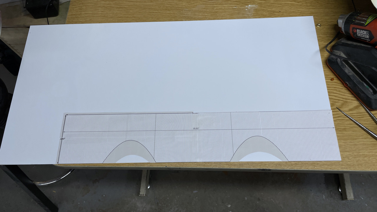
Good Feedback. I have to get some big photo paper. I’m thinking to affix to the back Plexiglass so it’s an integral part of the display rather than a separate piece that could get misplaced.

I seemed to have missed an entire post from yesterday’s work. So I’m adding it here in front of today’s post. Both were pretty intensive sessions with lots of stuff to show.

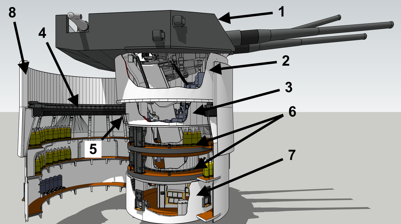
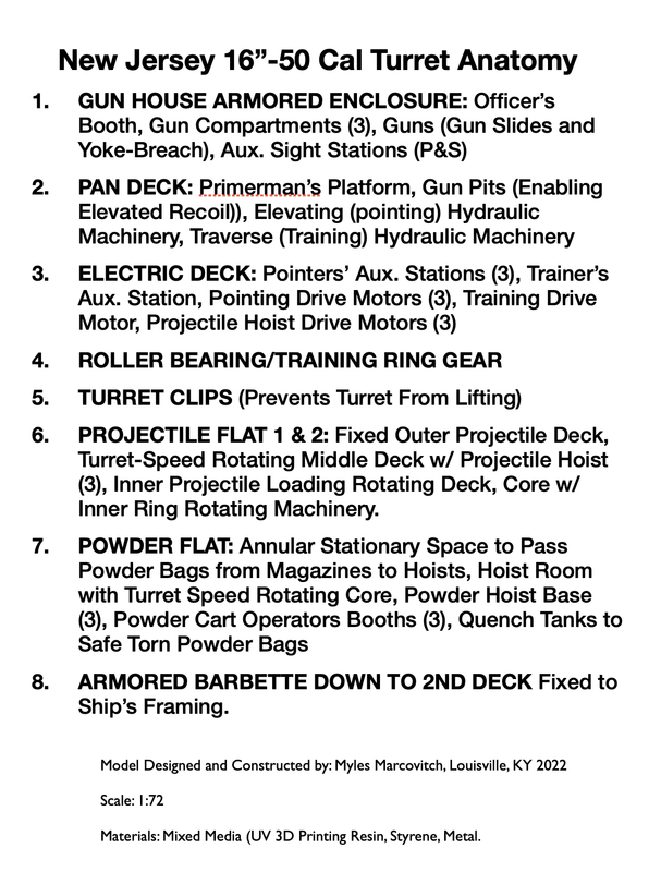
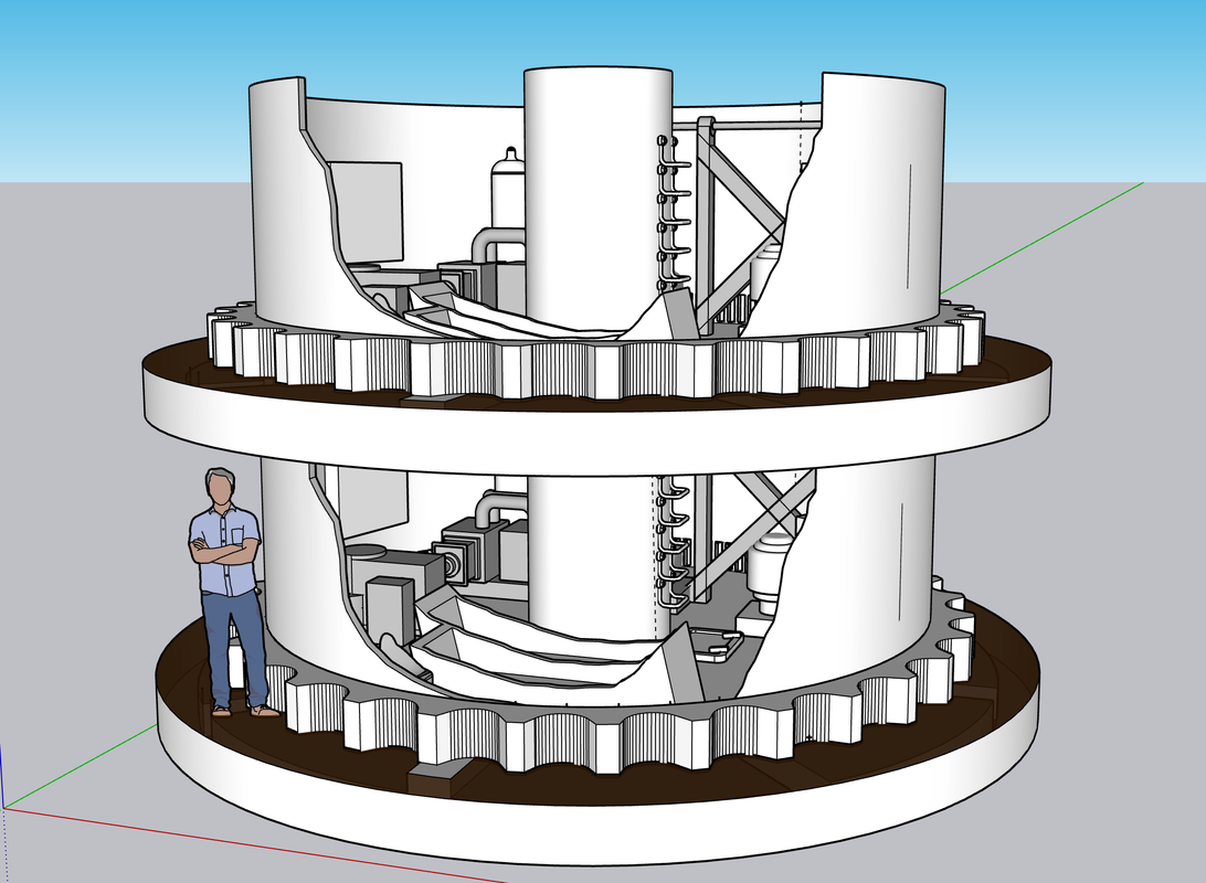
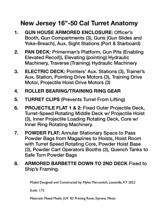
First of all I edited the turret drawing to display the main deck and what lies above and below it. It was a suggestion by one of my many readers. It quickly tells the viewer just how much of this machine is below their feet.

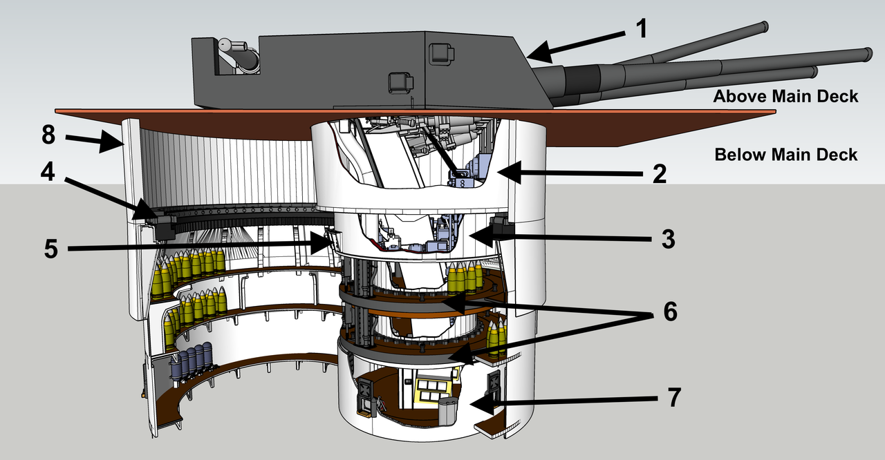
I made that correction suggested on the write up to spell out “Port and Starboard” and avoid acronyms.

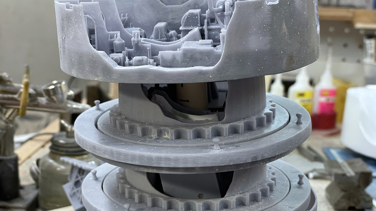
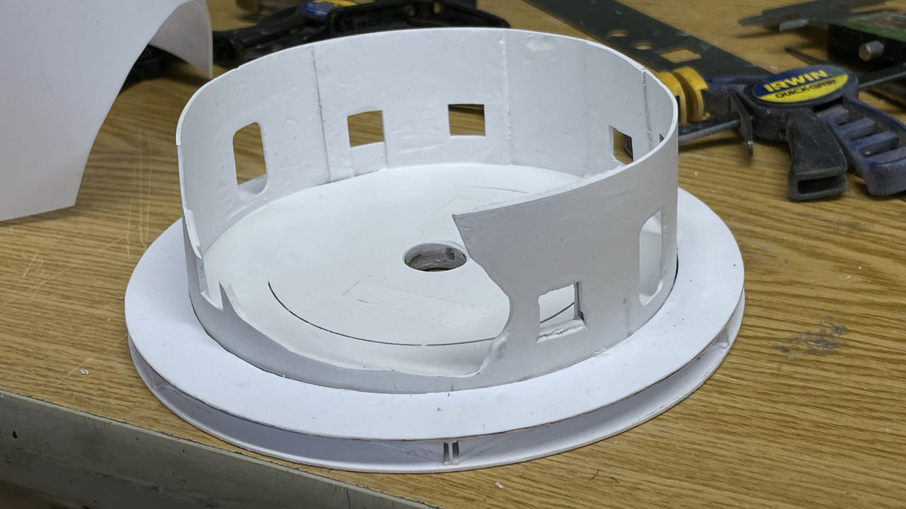
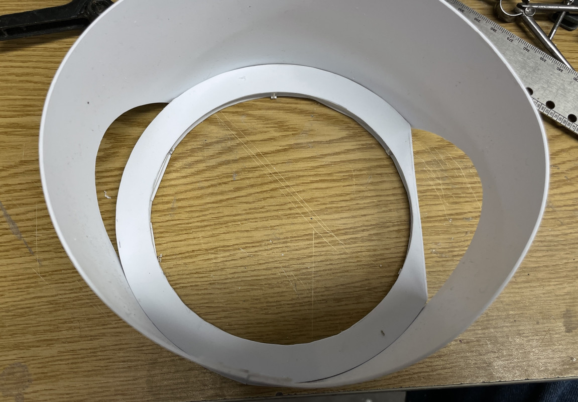
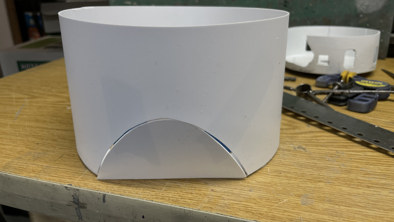
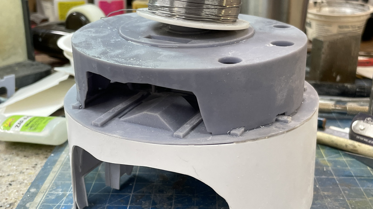
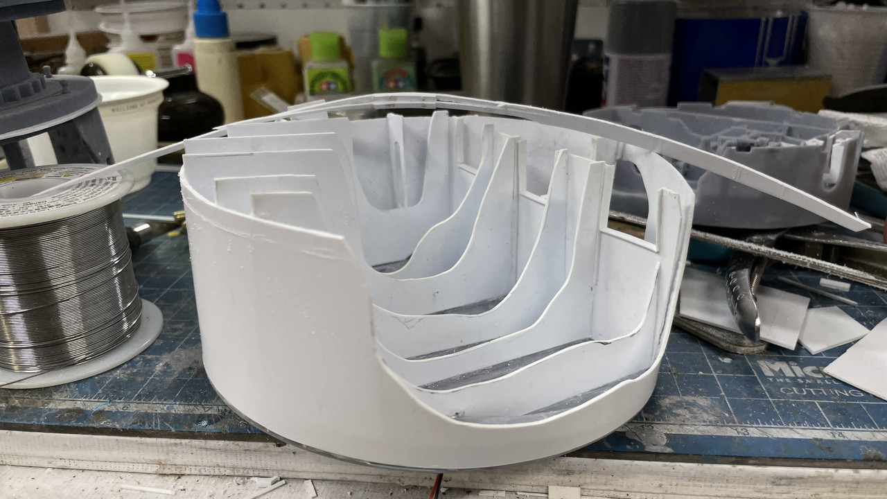
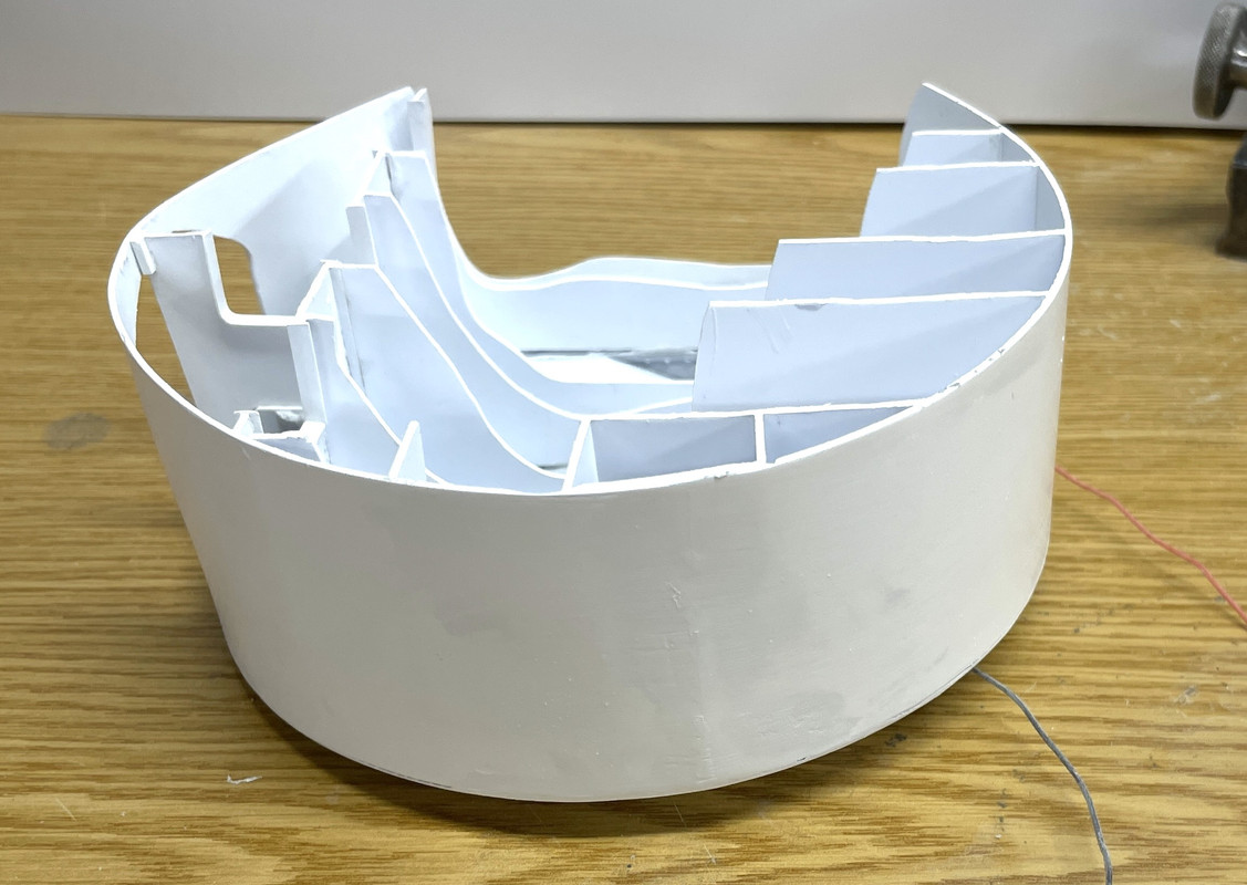
I took two steps forward and two steps back yesterday. I finally got the pan deck and electric deck to mate. After chopping and cutting all kinds of places on the e-deck, and still having the rocking to and fro, like there was a high spot somewhere buried inside, I decided to do some lateral thinking and check the pan deck base. And of course it was bowed out. It was this prominent bow that was created the interference. I should have relized this earlier, since the inner surface was bellied and the partitions had gaps that I had to fill… a lot. I used a sanding drum on the Dremel and knocked down most of the bulge on the ribs and lo and behold, the two gets finally got it together!

Another view:

I’m really having deja vu here… I know I wrote all this stuff yesterday and have no idea why it doesn’t appear on any of the four forums to which I post. I do all the basic text here since Fine Scale has the most cumbersome photo upload, having to first load to a service and then to this site. All the other forums you can just drag an image from my files and drop it in.

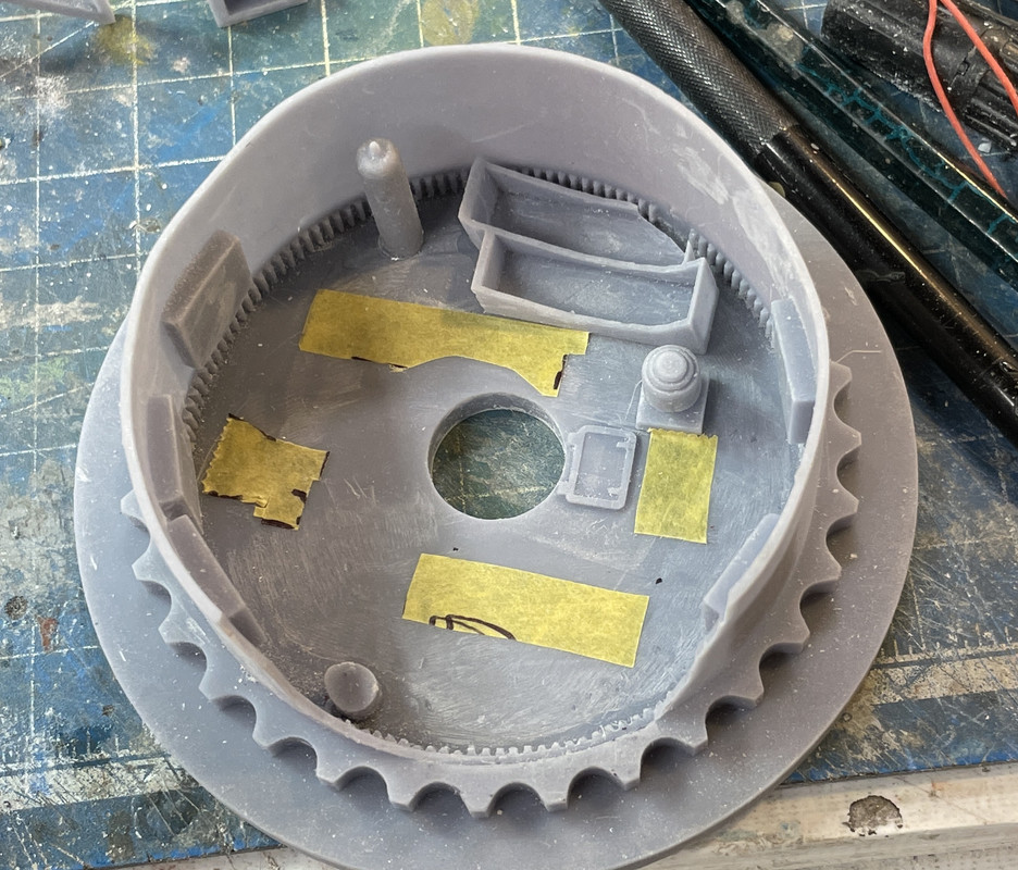
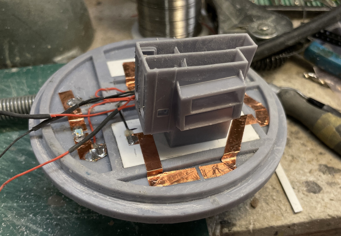
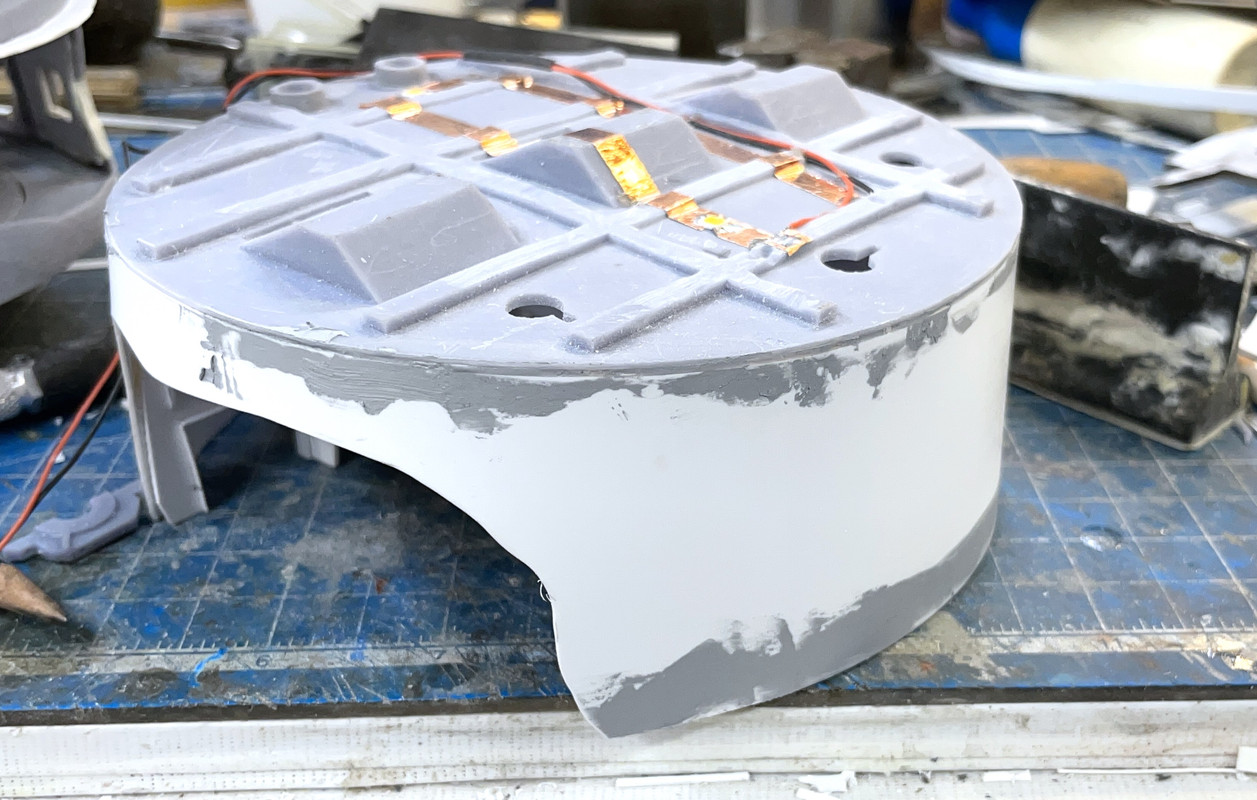
I wanted to get the pan deck ready for paint, but that required doing the electrical work first. I’m using surface mount warm white LEDs driven by CL2N3 LED driver chips. These little marvels cost about $0.25 a piece. You pump in anything direct current voltage from 5 to 90 and out pops 20 milliamps, just what LEDs love. No worry about current limiting resistors. You can string the LEDs in series limited only by the input voltage drops across each LED. Generally they drop about 3 VDC so you can run a 4-LED string with one CL2 on a 12VDC power source. I’m using a 12VDC LED power supply from Amazon that cost about $15. I’m using them all over the place on my model railroad and have another as my LED test rig.

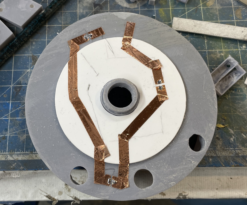
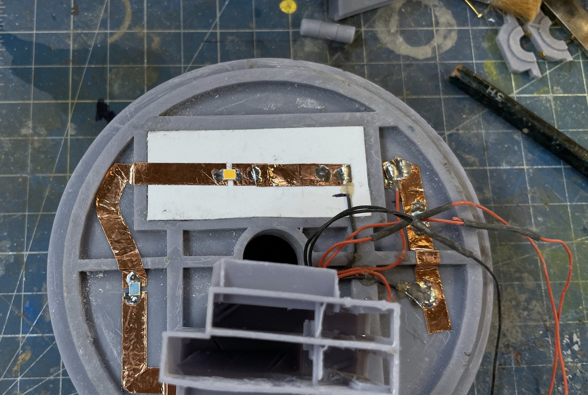
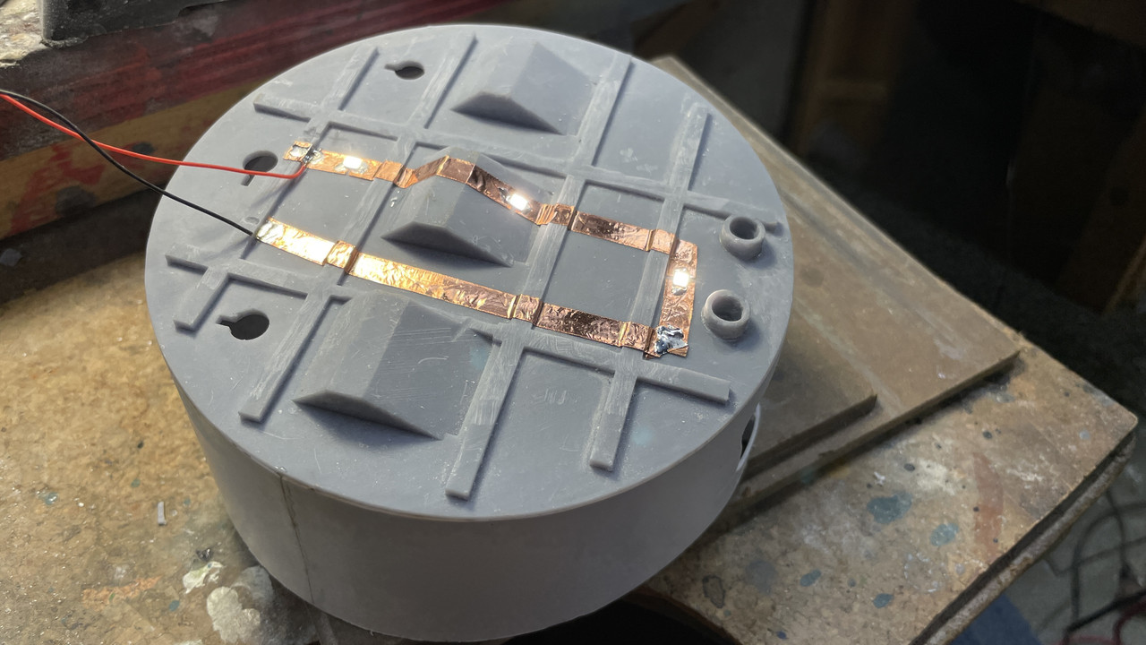
The circuit consists of self-adhesive copper foil tape with the LEDs soldered into little 1mm gaps. I mark which end is positive (+) and negative (–), and ensure that I’m soldering them in correctly. The contact pads underneath the LED is tiny, and the + is much smaller than the –. I run the circuit in a loop where I want the light to be and cut the notches. I use the continous corners that I was taught in installing burglar alarms in the late 1970s when we were using adhesive lead foil on windows to sense breakage. You bend the tape back on itself, then turn it 90 degrees to form a triangle and stick it to itself. I pre-tin both sides of the gap with enough solder to puddle a bit when I place the LED over the gap and heat the solder next to it. You don’t heat the LED! They are temperature sensitve. I heat the foil next to it and let the solder, keep a little bit of pressure on the LED with a tweezers, and as soon as the solder melts and the LED drops into it, I take off the heat.

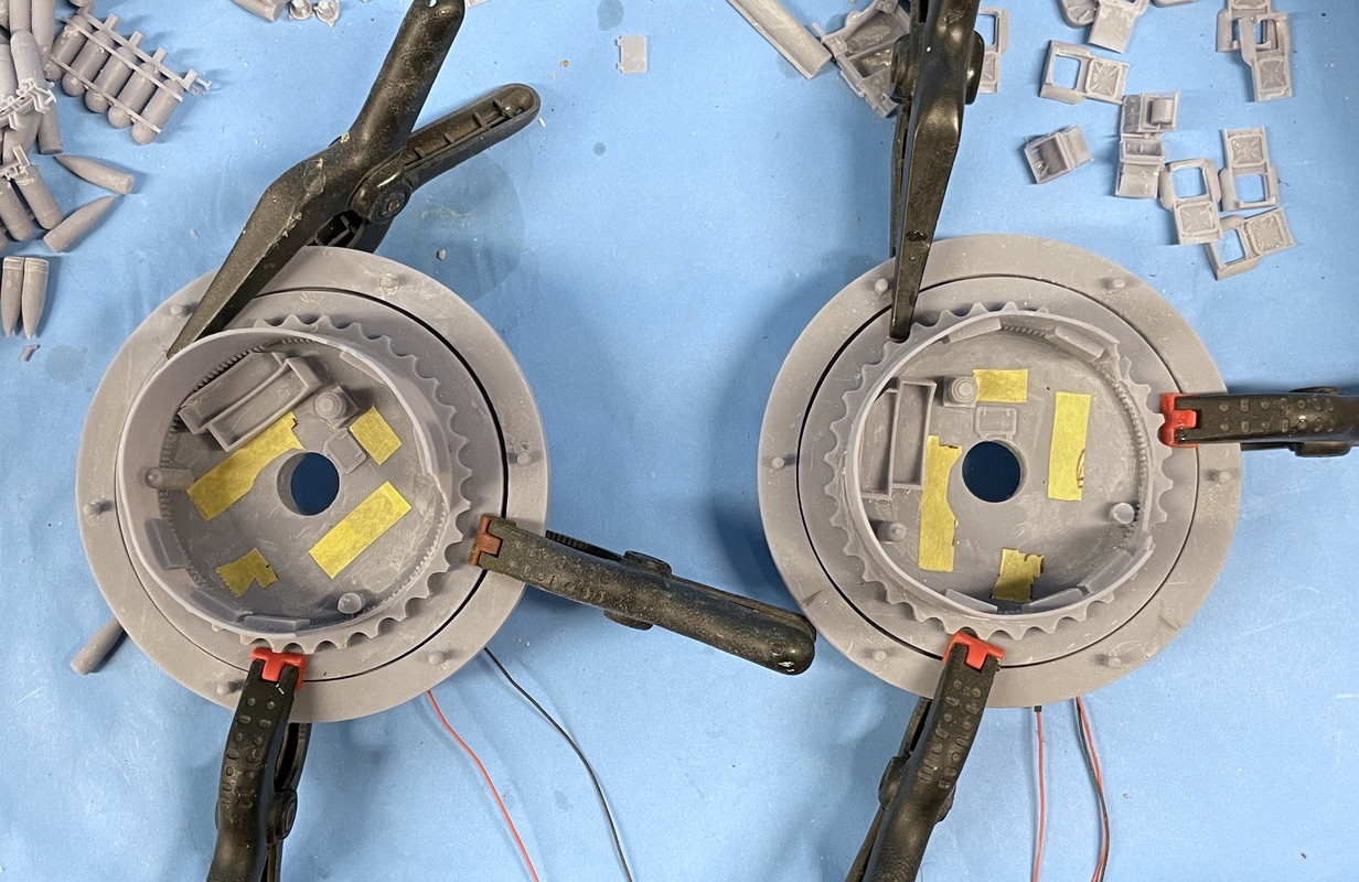
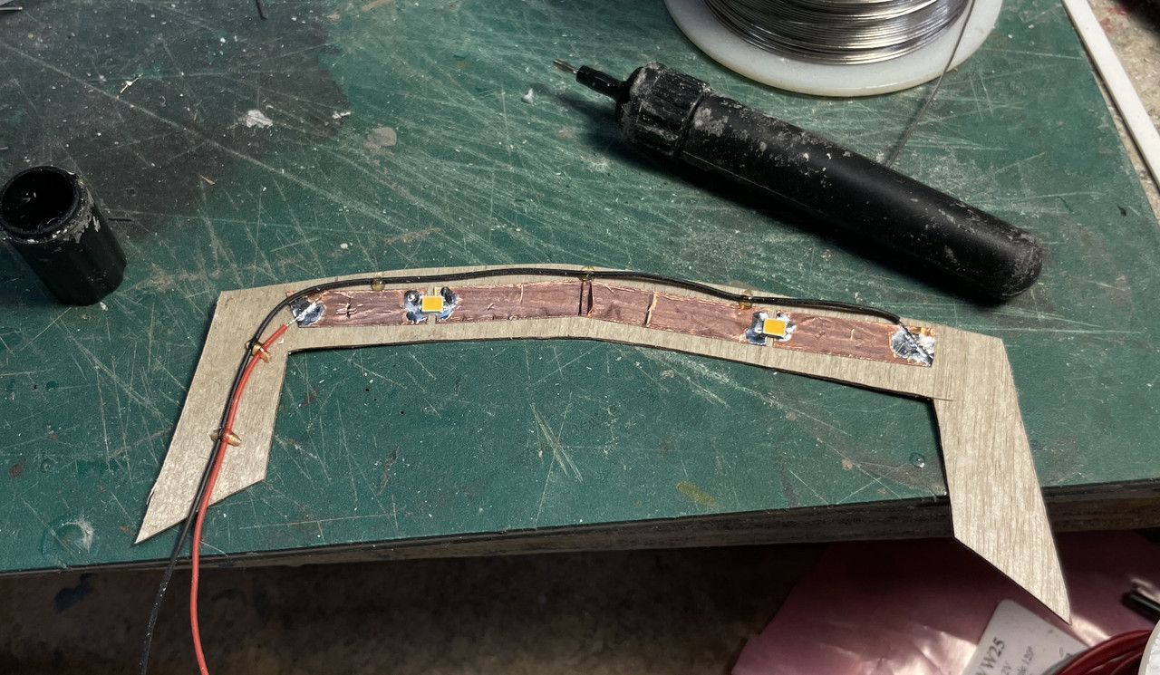
Here’s the illuminated circuit. BTW: If you get the polarity reversed it doesn’t damage the LED. They’re diodes and simply block currect in the opposite directoion. These puppies are very bright and I may have to attenuated them by painting something on the lens. They are much brighter than they appear here. The wire is 30awg silicone insulated stranded. There’s is very little current in this circuit and small wiring works perfectly.

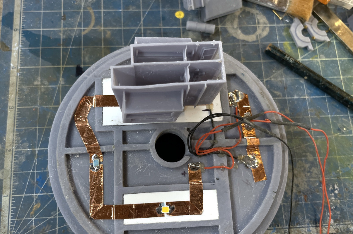
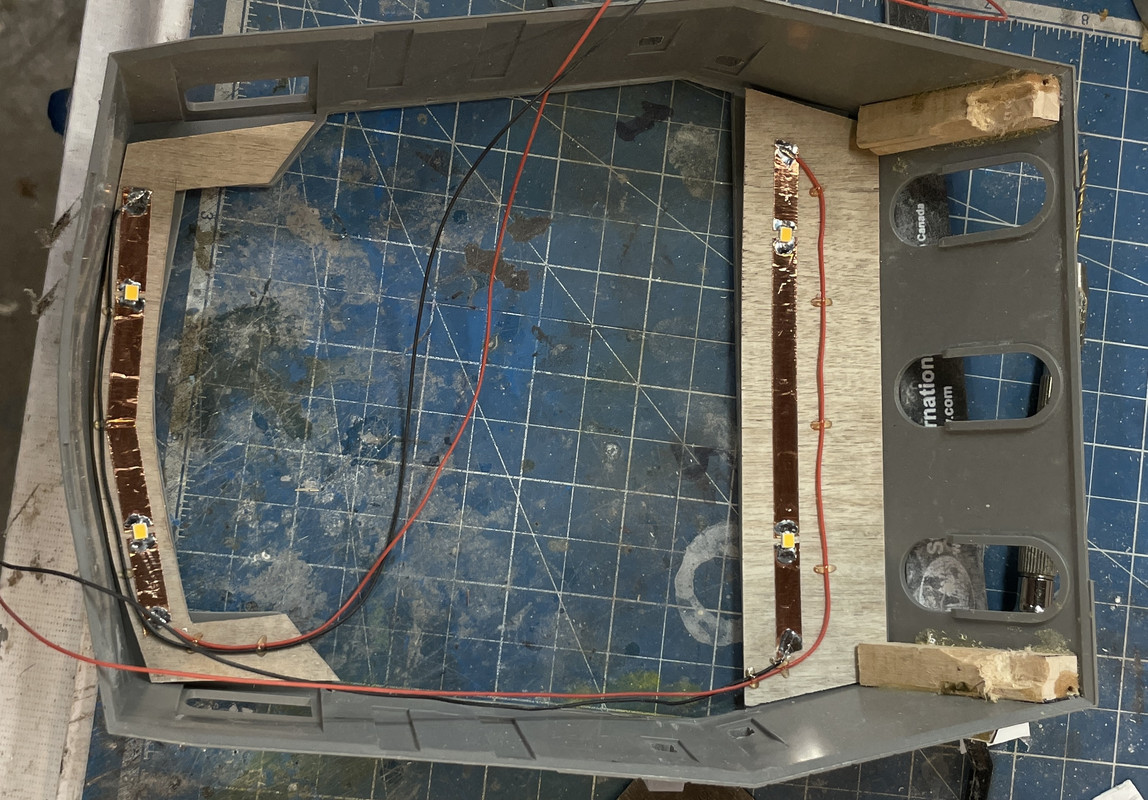
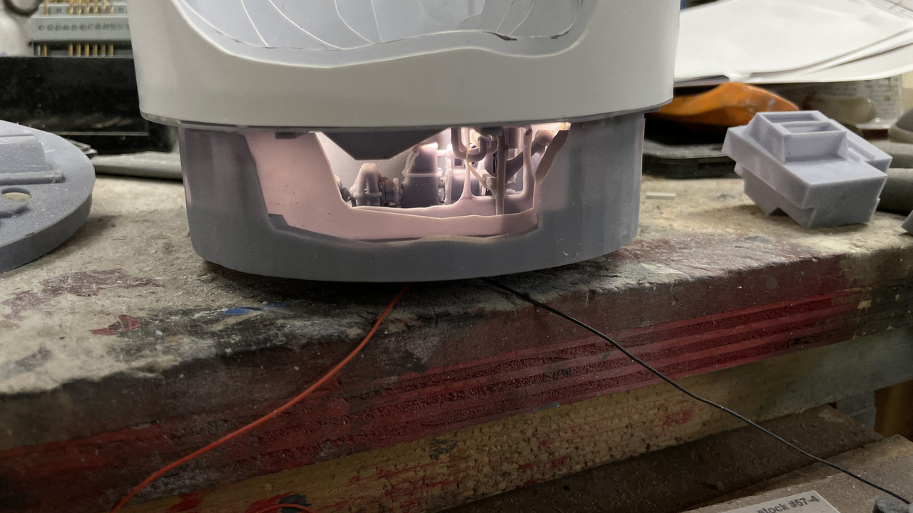
And here’s the e-deck lit. The translucency will be elimiated by the many coats of paint to follow. If it still shows up, I can back the panels with aluminum foil which totally blocks the light leakage. Half of this stuff will not be visible when the powder trunks go in.

Now to the ugly stuff.

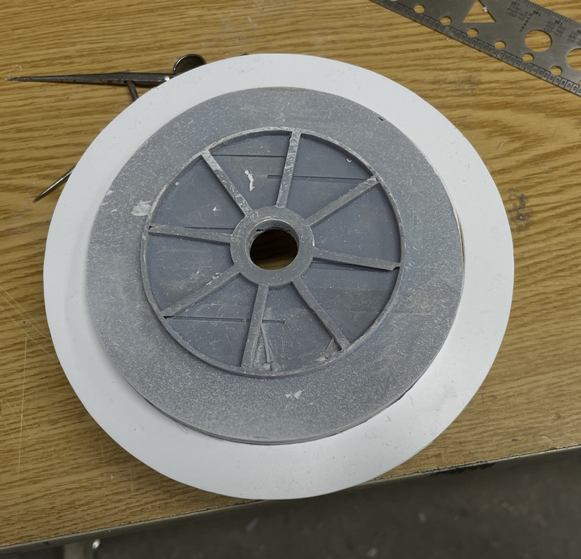
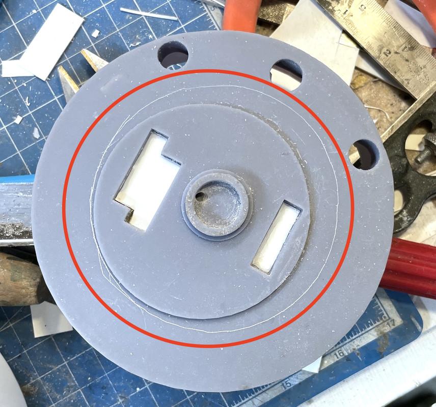
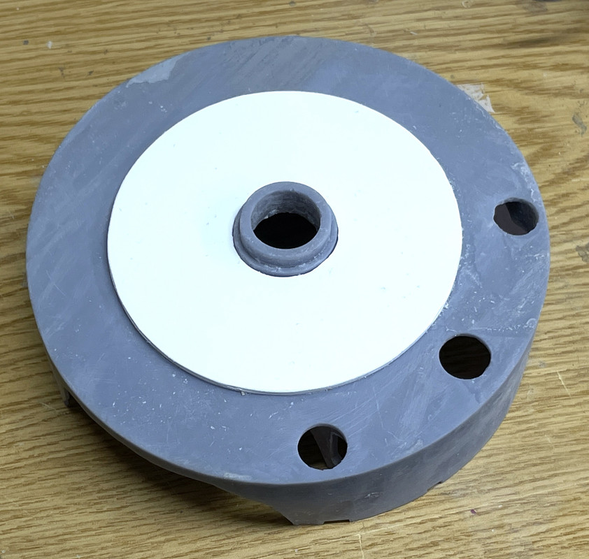
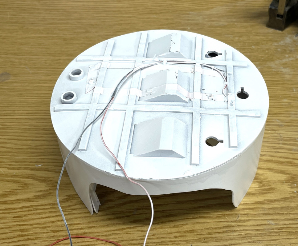
I found that the boss on the bottom of the e-deck was completely off-center. The central hub was fine, but the surrounding circle was eccentric. I scribed a circle of what would be correct. I was going to attemp to repair it, but last night decided to print a corrected part which you will read about further down in today’s post. Don’t ask me how this could happen. I don’t have a clue. Every (or nearly every) circle I draw in SU is concentric with others. It’s very easy to do.

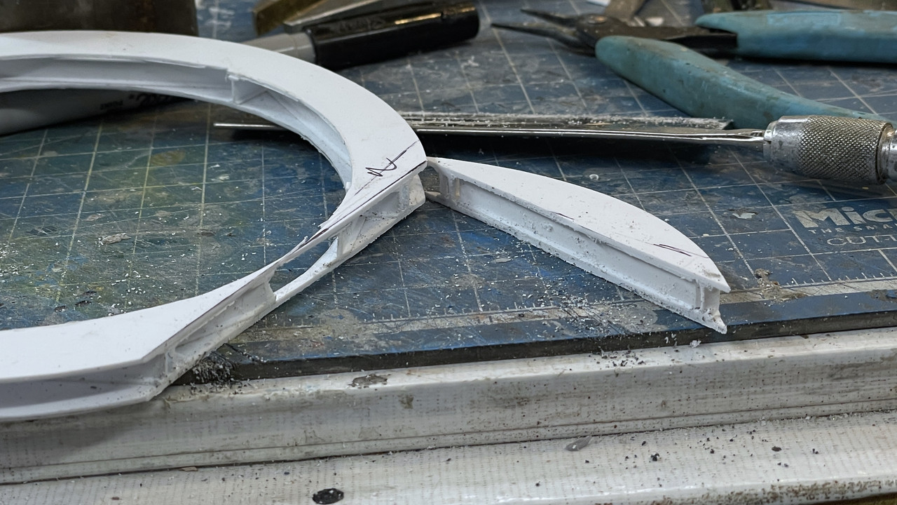
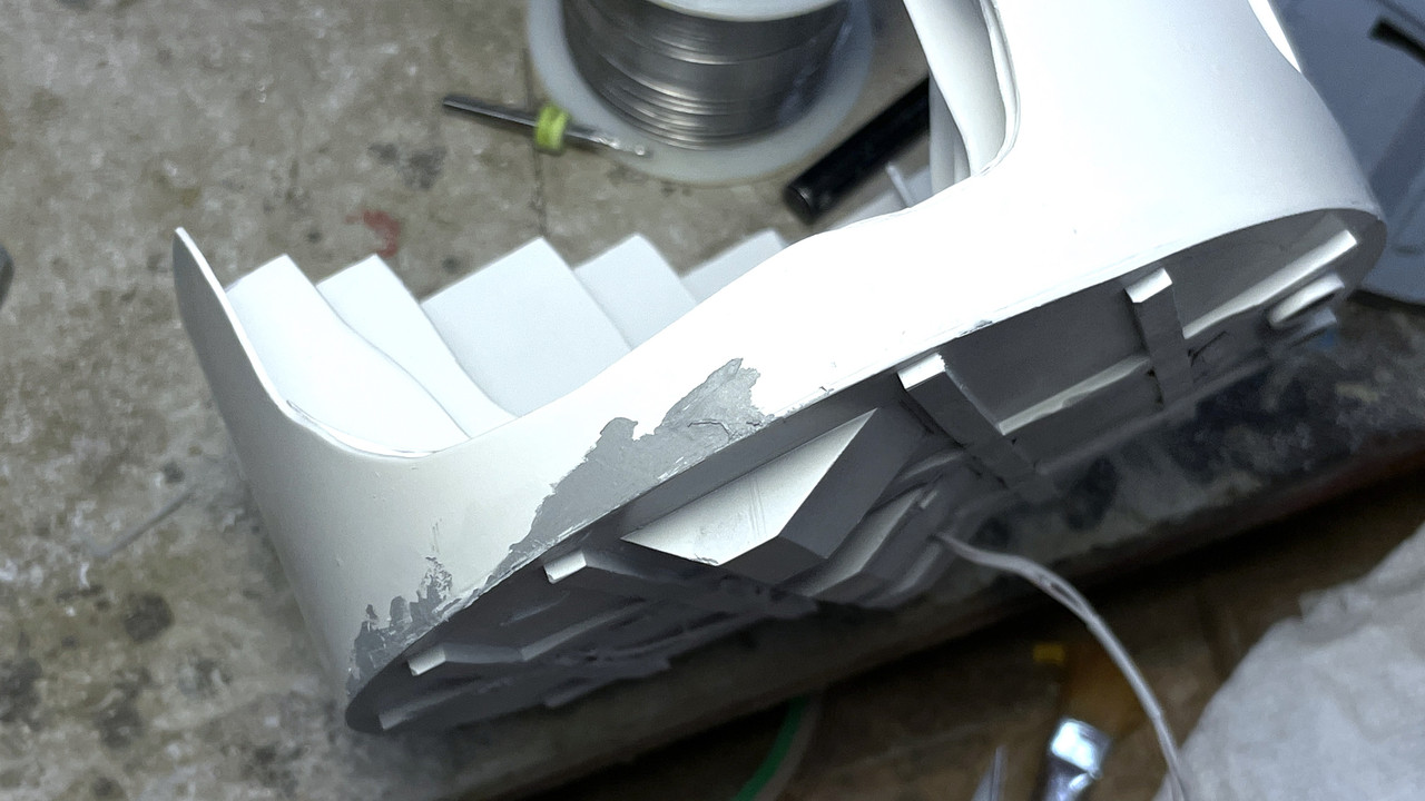
The other problem was the uneven wall height arround the pan deck perimeter. This had to be fixed. I used a surface gauge and scribed a line from the lowest wall point around the entire circumference. I then used an abrasive wheel in the Dremel and removed anything that was higher. It was a scary bit and could have wrecked the whole deal, but didn’t. Today I trimmed all the rest of the stuff that was sticking up. I don’t know what this amount of material removal is going to do with the final constuction. In actual practice the gun’s recoil would possibly be too long for the ceiling height at full elevation. But I’m not elevating that high AND my guns can’t fire and therefore can’t recoil. And it may be a benefit. I may have made the elevating scews too short, but this extra 3/16" could be all I need to have them comfortably fit into the tilting boxes.

Today’s post:

Still wrestling with the real world versus the 3D designed world. It’s a shock when I find my brilliantly designed things don’t quite translate into the solid objects of which this world is made. Case in point…

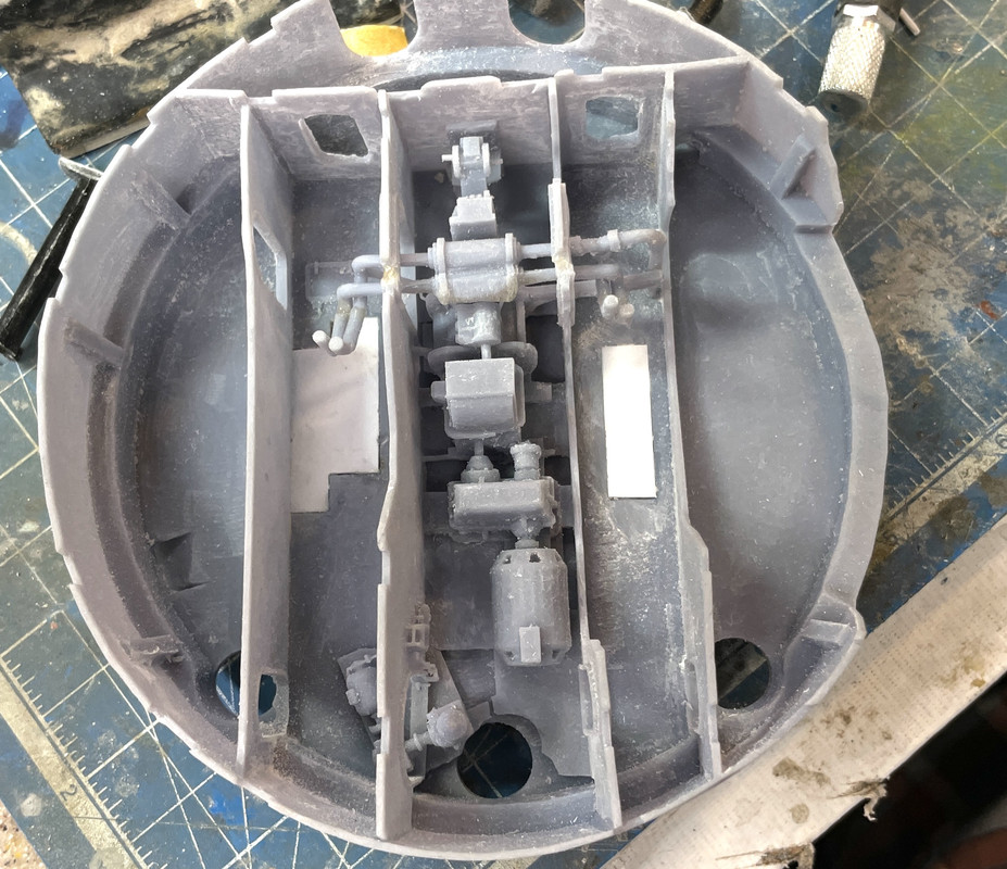
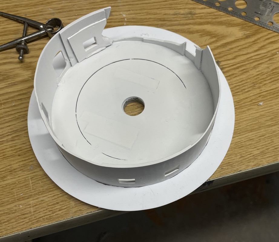
I decided to reprint the electric deck and the insert. There were aspects of both that could be improved and I had already drawn a later version of each. The big print worked overnight so it was waiting for me this morning. It wasn’t bad although again it had large ribs in places that weren’t on the design and again, I was able to surgically remove them without damaging what was there. The bottom of this new part did not have that off-center boss problem like the previous one did. In fact, it had no boss at all. Furthermore, to add to the fun, the center lug that sits on top of the central column, was not physically attached in the drawing and printed anywhere as a separate part. It was so well supported it just print right where it was, but fell off when I removed the support. I glued it back on with Gel CA.

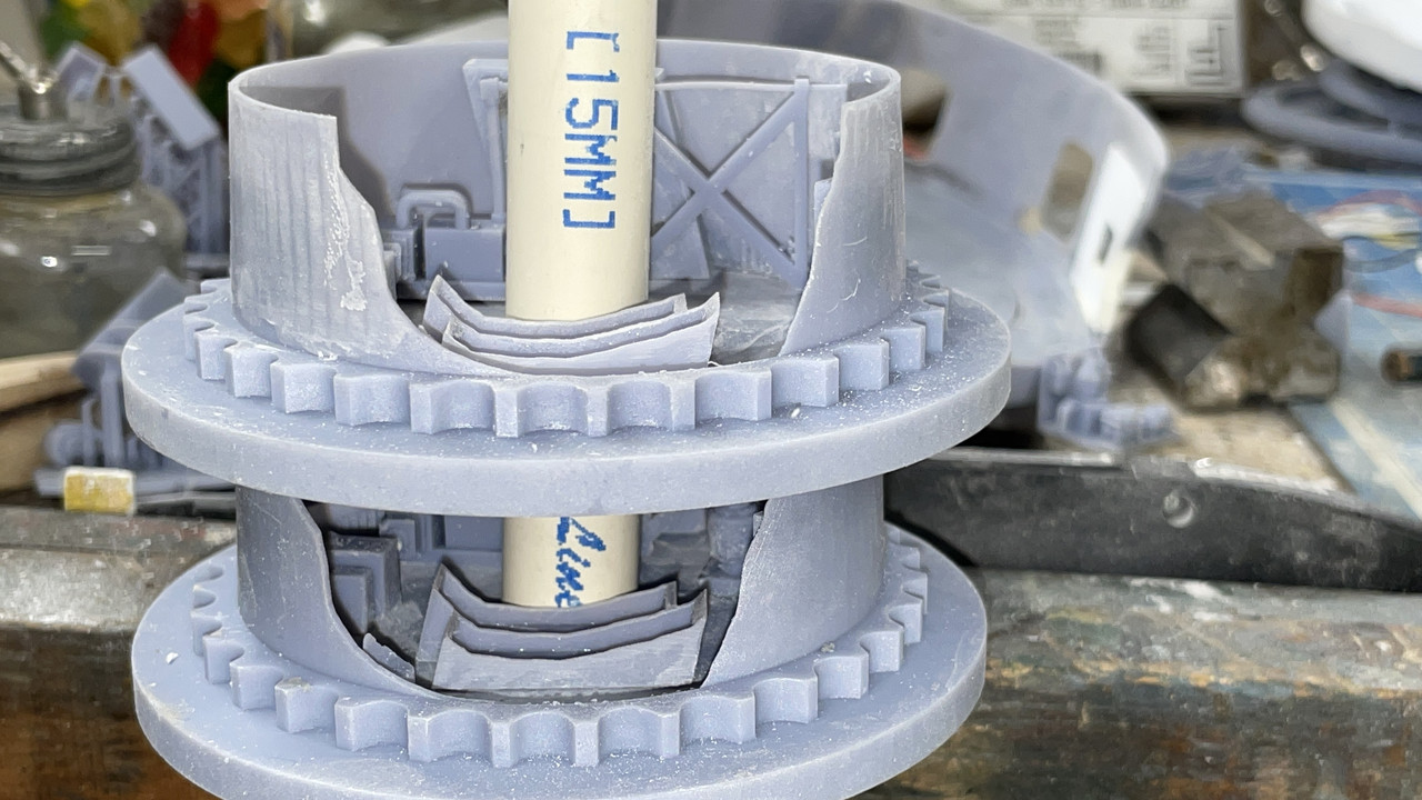
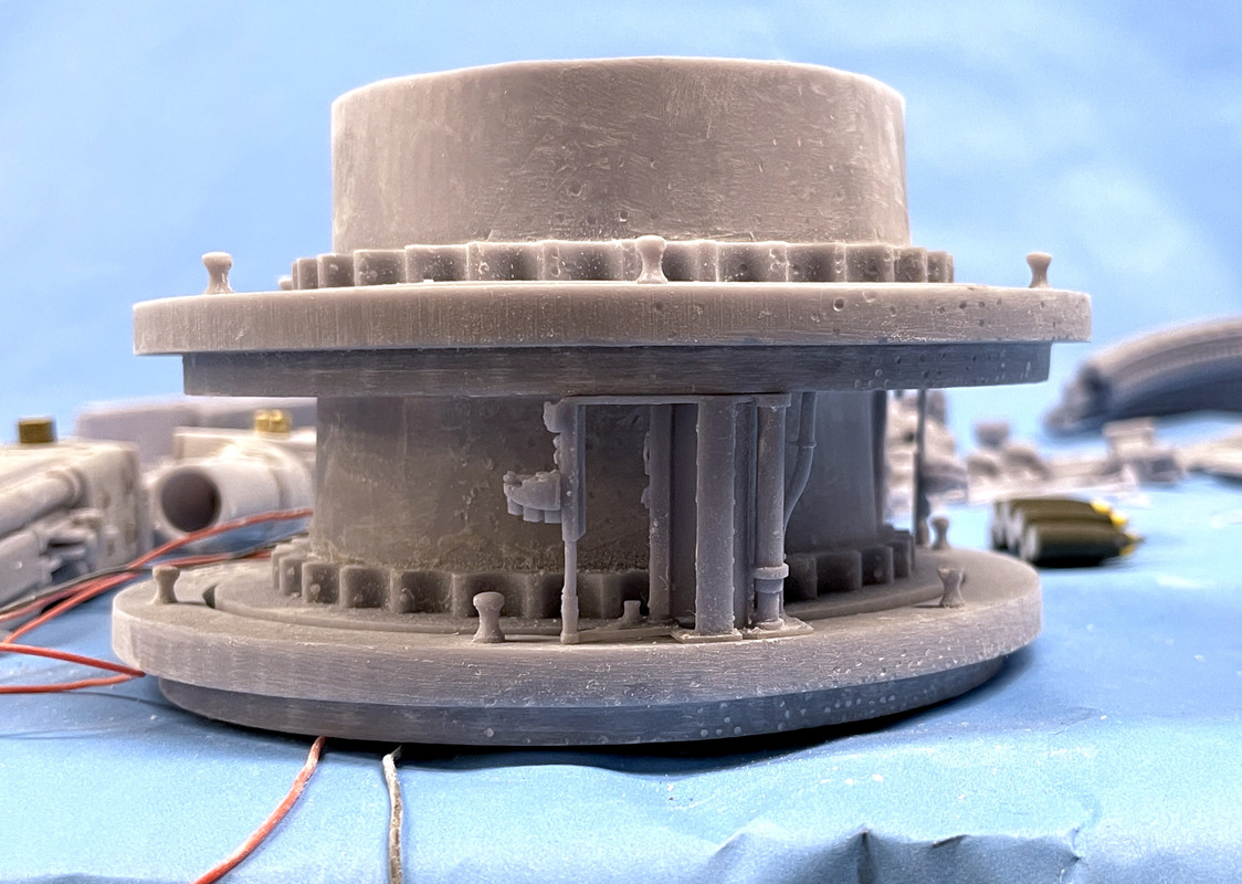
I thought it was good that it didn’t have a boss, but then found that when I assembled it with the projectile flat that lies below and added the projectile hoists, the electric deck was sitting about 0.080" above the projectile deck’s inner drum held up by the projectile hoists. It NEEDED THE BOSS!

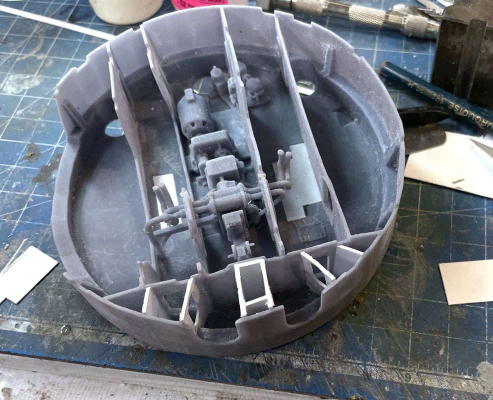
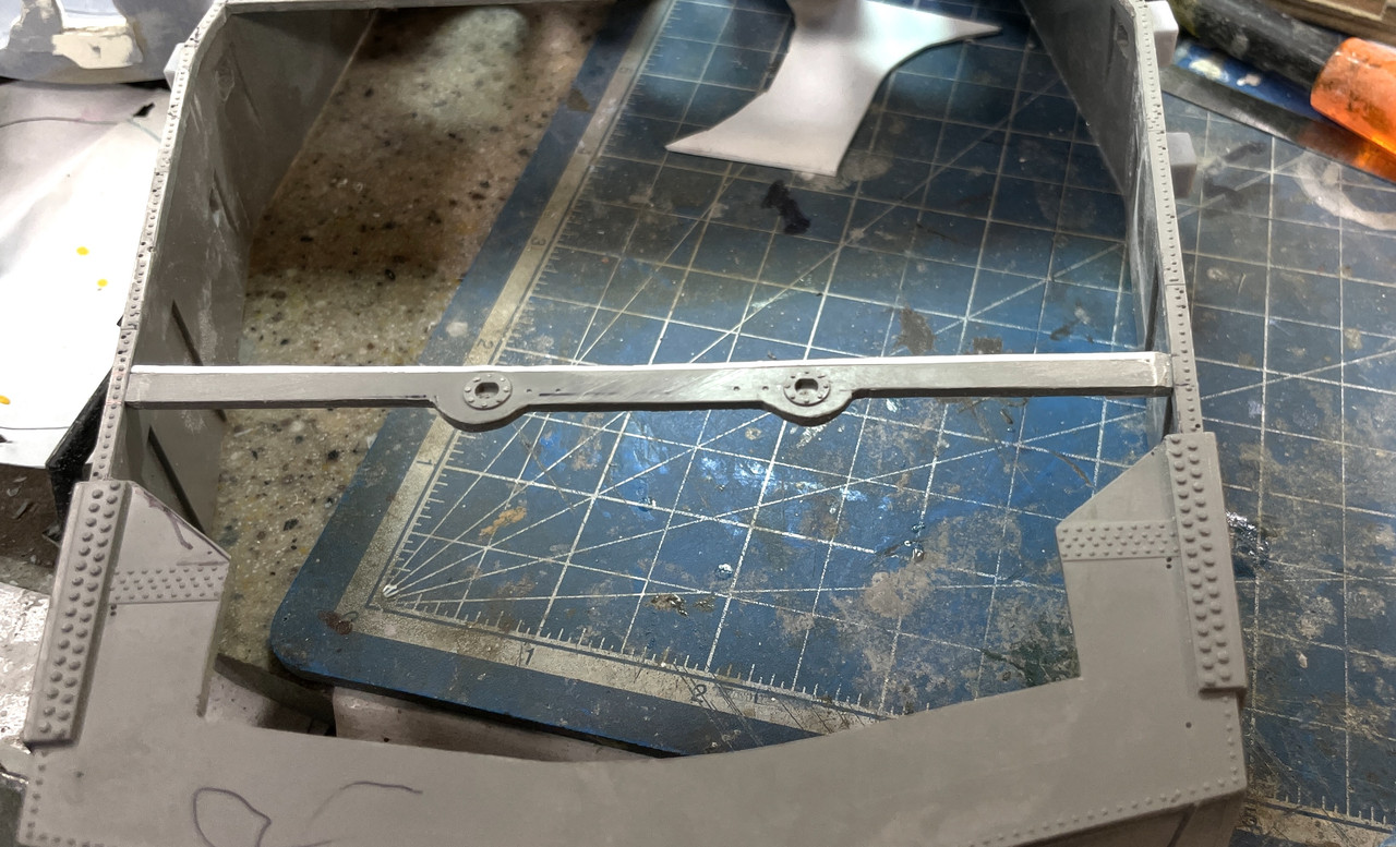
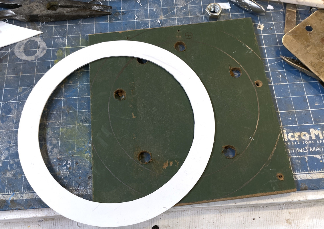
I made the boss out of a laminate of two pieces of 0.040" styrene, and attached it using 3M transfer adhesive tape. This stuff is contact cement that comes on a roll. I can be amazingly strong when applied to clean surfaces. The spacing is now corrected.

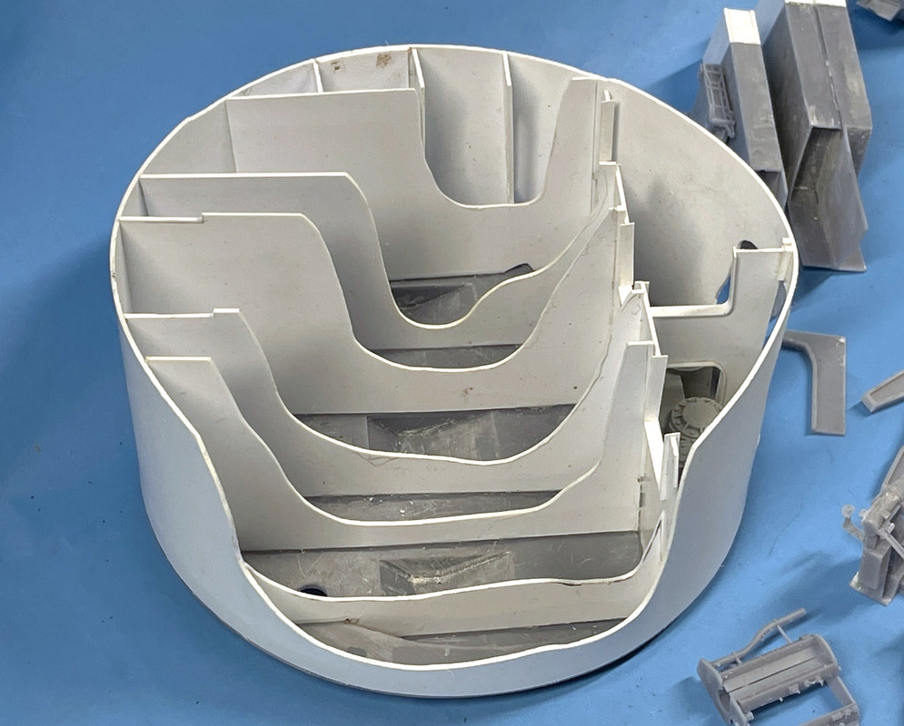
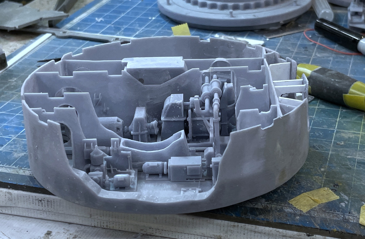
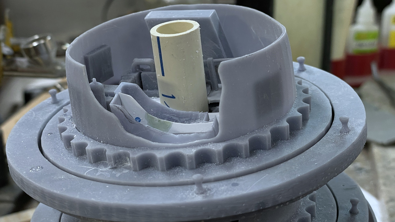
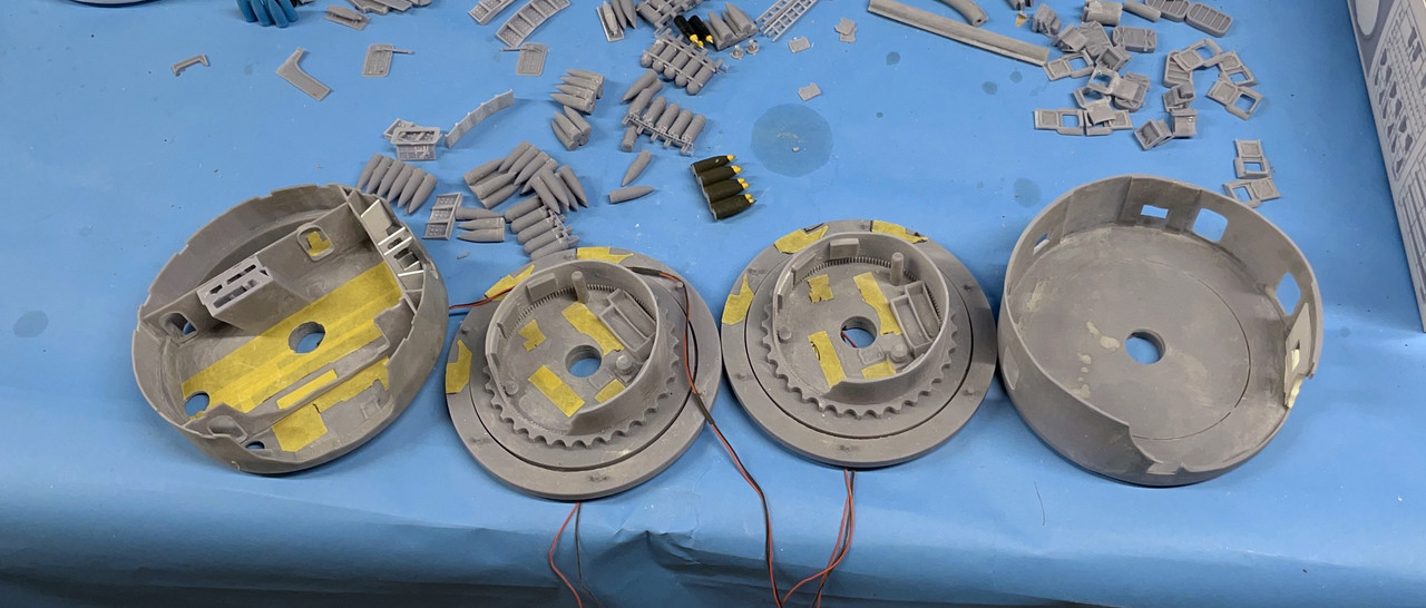
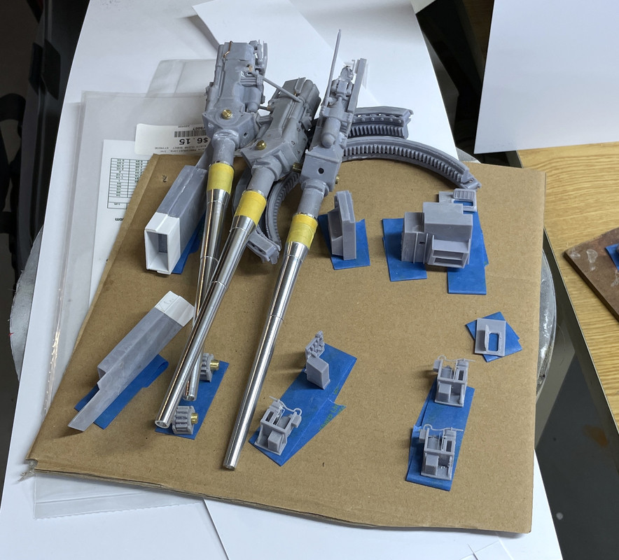
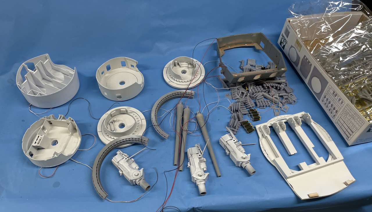
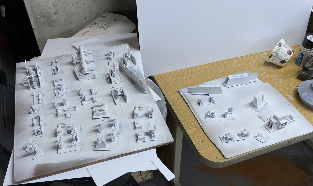
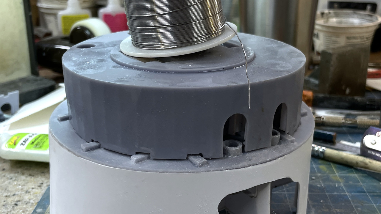
I spend more time on the projectile deck centers starting to get the powder hoists trunks final fit for installation. i also chose to install the other apparatus in these inner spaces. Visibility is terrible inside due to the vision blocks set up by the powder trunks. I suppose I could hack some material off of them to show what’s behind, but I’m not inclined to do so.

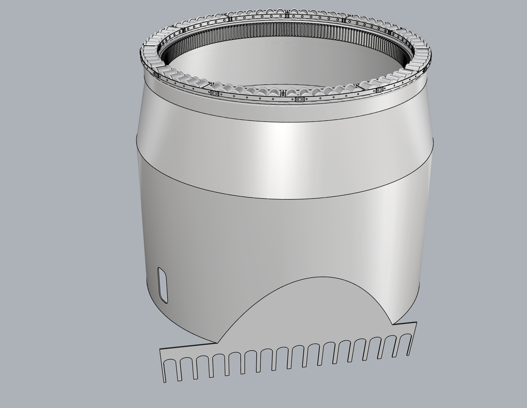
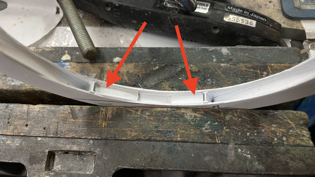
I finished up leveling the wall tops of the pan deck and got it ready for paint by finish sanding and filling the outer surface. I double-checked the drawing and flat pattern created by the software to see if the errors were there. They were not! The entire length of the pattern was parallel. What I think happened were errors crept in during the bending and glue up. It’s a conical shape and depending on how the final joining was made, it could have changed the height of the sides in places.

After sanding I went around and filled any gaps in the styrene-resin interface with Tamiya fine filler.

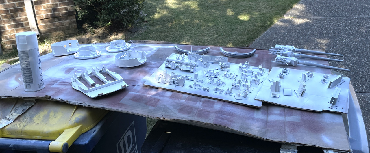
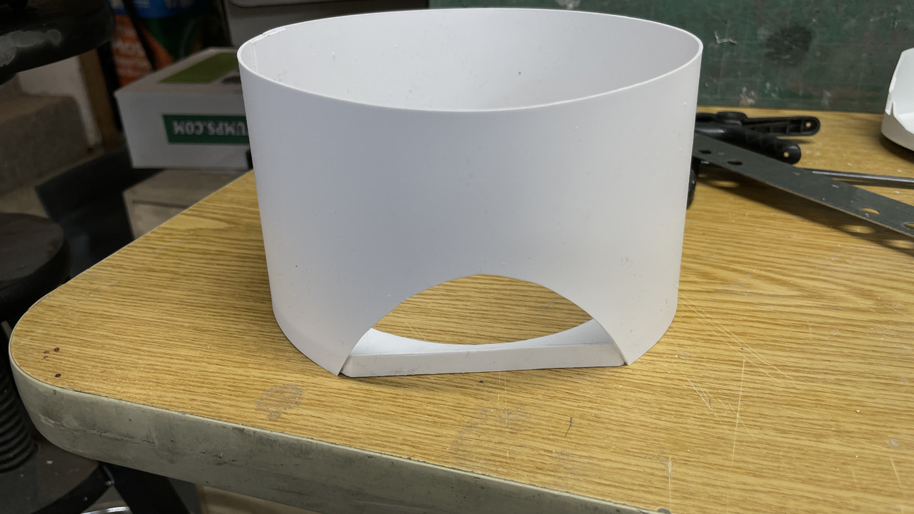
I took the pan deck outside and rattle-can sprayed it with Tamiya White Primer.

And after using Molotow Liquid Mask, I did the bottom.

I put a final coat of filler on a few missed spots and will sand that in tomorrow’s session.

I’m going to paint the wall gloss white, the floor will be linoleum brown, with the apparatus painted medium gray. Ladders and projectile hoist trunks will be white.

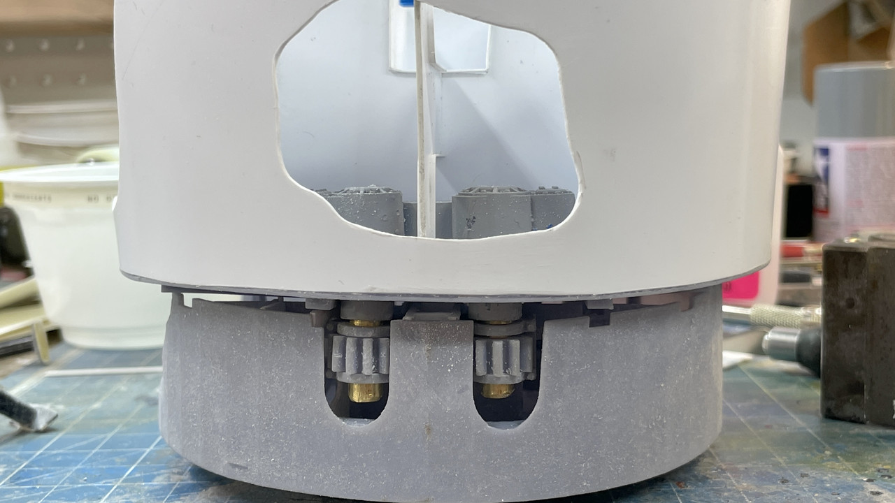
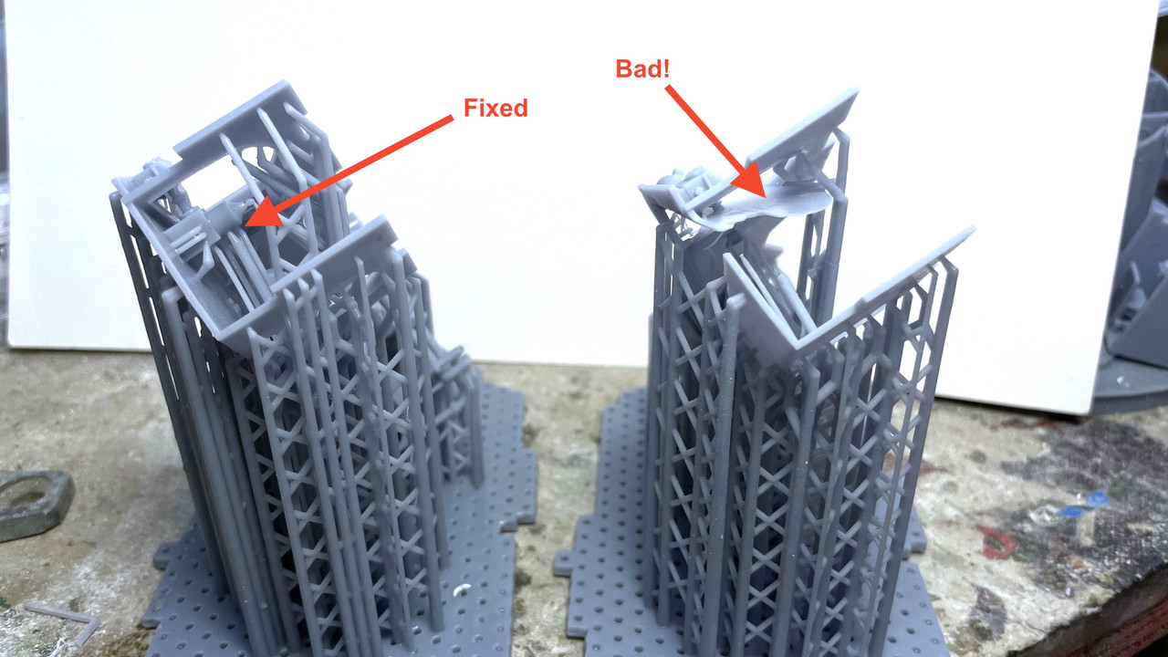
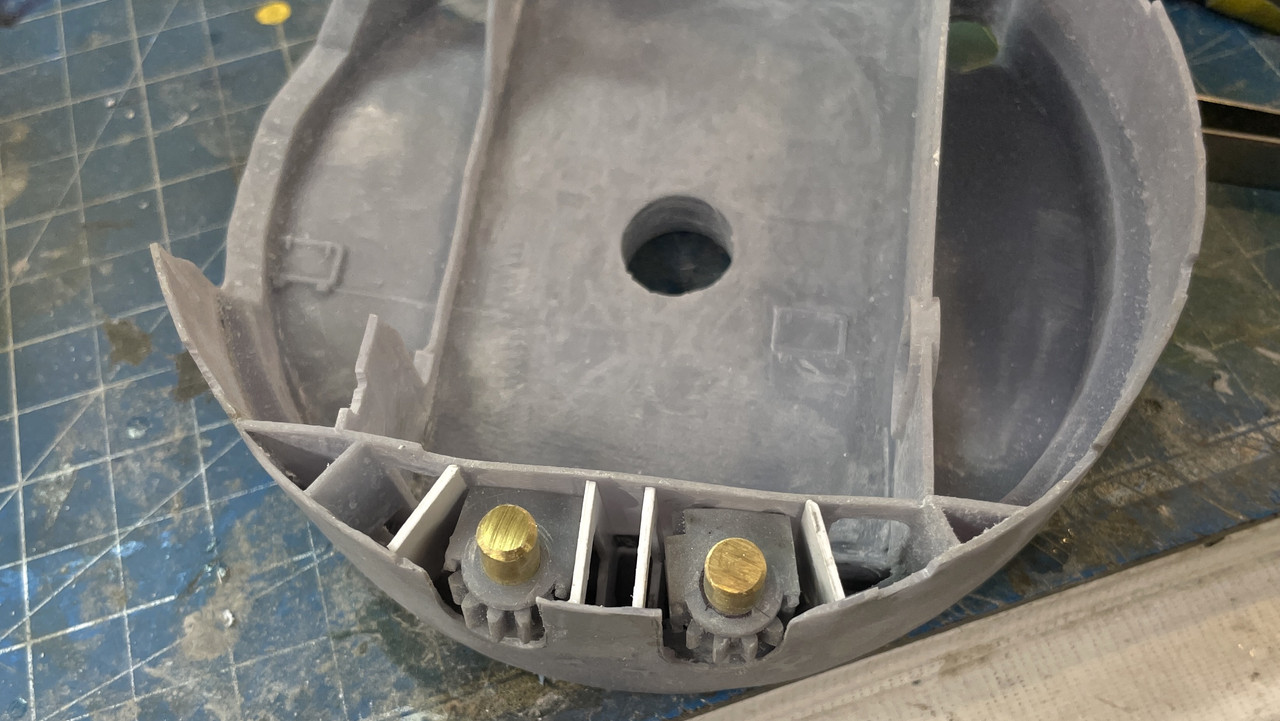
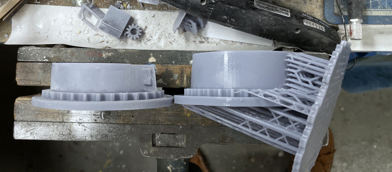
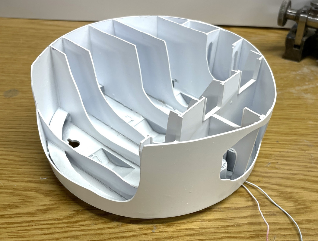
Next up was the E-deck reprint. This print, besides missing the bottom boss, had the front bulkheads printed in place and they looked good (except for the middle piece of the front wall and two of the arms breaking off during cleaning). There was just one small problem. The pinion gears and their housings couldn’t go into the space. Once in the space they would possible work, but I couldn’t get them in there.

They fit in the drawing! That’s becasuse, they aren’t real and could move through the parts that were in the way into the space where they did fit.

It is essential that the pinions drop straight down into the space without a lot of wrangling. It’s part of the entire pan deck structure and that’s hard enough to get into place without having to hassle with the gears. So I took the router and removed the four inner bulkheads. I left the outer two in place. I will scratch-build them as I did with the last version, out of styrene spaced wide enough so the pinions fit

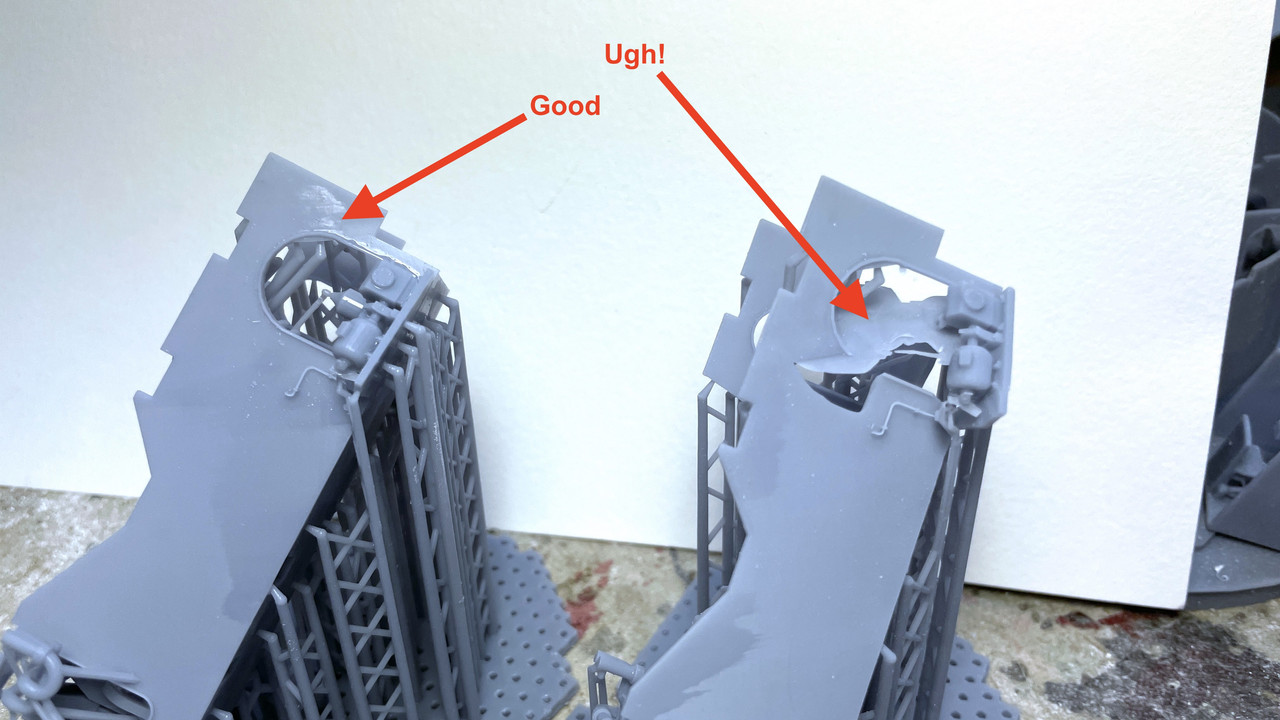
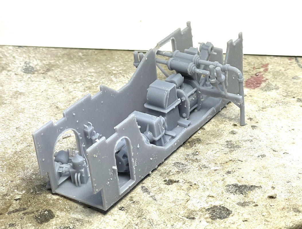
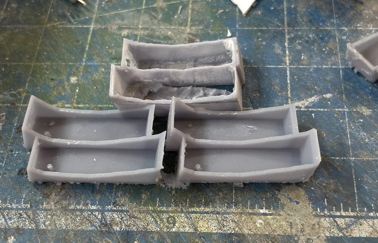
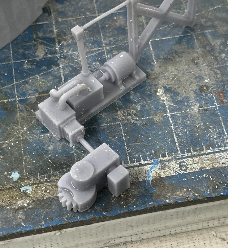
Re: the middle appratus print: The print was perfect except for a mal-formed wall and projectile hoist power unit that sits across one of the bulkhead openings. I will surgically remove the bad stuff and transplant a good from another print I have. NEVER EVER THROW AWAY REJECTS UNTIL YOU’RE ABSOLUTELY SURE YOU WON’T NEED THEM!

Tomorrow will be the last work session for over two weeks due to the Hawaii trip. I will still have access to the forums so I can respond to comments.

Last short work session before vacation (now… really…when retired you don’t “really” need a vacation. Everyday is a vacation). I finish sanded the outer walls of the pan deck and powder flat. Continued mounting stuff into the projectile flats, and reprinted successfully that complicated mid-section of the electric deck.

I woke up thinking that why should I spend the effort to cobble together a good part when I know exactly what failed in the print and know exactly why it failed. It took 10 minutes to add and modify the supports so that area wouldn’t fail. I put it on the machine in the morning, did my exercises and by 3:30 p.m., the part was done.

These two images show the failure and the success.

It was actually the good kind of failure: nothing was separated from the part and stuck to the FEP.

After support removal and a couple spots needing some Bondic, this is what it looks like. It only took four iterations to get this one right. it was a complicated part that stretched the envelope of a single part print.

When we return from the trip, I will grind off all the support scars. This version has the corrected pipe positioning to align with the training B-end one deck above.

And with that I see y’all in a couple of weeks.

Hello!

That piping looks really good!

You make 3D printing look really easy - thanks also for showing that there are potential for complications!

Enjoy your vacations!

Paweł

Aloha! (that word and Moholo) is the extent of my Hawaian vocabularly after spending 12 days in paradise. It lived up to its expectataions and besides spending a small fortune, we really did Maui. We don’t do serious hiking, paragliding, jetskiing or any of that ‘rough’ stuff, but we did do a lot of fabulous restaurants, visited a distillery, a winery, a glass factory, two botanical gardens, aquarium and walked on beach trails that gave views like this…

and this… This was outside our hotel balcony.

Maui was created over a million years by two volcanoes. Actully the five islands that make up Maui’s neighborhood were all one island many years ago and between subsidence and errosion, the connecting land bridges submerged. It’s why the channel between Maui, Lanai, Molokai, Kaho’alawe and the Molokini Crater is so shallow. The West Mountains are the remnants of a volcano that last erupted about 1,000,000 years ago, but the other, a 10,000 foot monster, Haleakala, erupted just 200 years ago, so it’s only “mostly dead”. The West Mountains, like the San Franscisco peaks at Flagstaff, AZ was once a huge mountain, but has broken down and erroded to a series of interesting peaks.

The best part of the trip was biting the bullet and renting cabanas during our four beach days. I am a true white man… I mean I am pitifully white, and sunburn just by imaging the sun in my head. Modern sun screen helps, but a cabana helped a whole lot more and made staying down by the sea for hours and hours much more relaxing. This was a view from our cabana watching the idiots going around in circles on jet skis and paying a fortune to do it. For the exhorbatent price of the cabana, they provided us with cold water and fresh fruit (including Maui Gold Pineapple).

We flew Louisville-Dallas-Maui-Dallas-Louisvile. The L’ville leg was on regional jets, but the Maui run was on an American 787-900. It was our first time on this plane and we flew Premium Economy. Premium Economy exceeded our expectations and seemed very much like business class (which I flew many time 20 years ago back and forth to Germany). I would recommend. It costs more than coach, but it’s worth it. Five years ago, we flew First Class on a United 777 and it was definitely NOT worth it.

Now onto modeling. Finally got back in the shop and I hate to say it, but it felt great! I picked up where I left off; fitting the center section into the newly printed electric deck and getting the rest of it ready for paint. The was very little clean up on the middle part to make it work. I had to open up the hole for the projectile hoist trunk, and sand off some divots, but that was it.

I then spent time re-creating those little bulkheads on the forward part of the e-Deck. So little of these things is visible from the enclosed front that it’s really not worth the effort, but you know… AWS. The pinions now fit this new space without binding. I also enlarged the semi-cicular pinion openings since the teeth were contacting the walls and weren’t able to rotate. I want them to rotate so they can seat properly on the large ring gear.

The e-deck is now ready to receive all the apparatus either painted or un-painted… haven’t decided yet. Assembly will continue more quickly now that everything’s ready to go (except all those outer shells).

[snWcm] Welcome back! Yeah that is a magical place, even for us from Sothern California. Glad the work is progressing smoothly, guess the time off was worth it- [H]

Really impressive progress and I think you’re heading into the hardest part of a complex assembly. I find my printed parts never quite fit perfectly; almost always everything is just a liiiiiitle too big…

Lots of shaving, sanding and handling = breaking, fixing and even reprinting!

You seem to be doing remarkably well though.

Hope you’ve smooth sailing and looking forward to the next instalment.

Duster, lots of Maui had a very S. Cal look to it. Lots of brown coverings of the hills. There’s a wet side and dry side and the dry side is very dry except during the rainy season. We were back and forth across the island a lot and almost put 600 miles on the rental. It’s almost constantly raining in certain parts of the upslopes on Mt. Haleakela and the Western Mountains, while it’s hot and dry in the low lands and the West/South sides of the island. Lots of strange microclimates just a few miles from each other.

Joe, you are absolutely correct. Just because you can make some fantastic shapes with resin printing, your model making work is far from over. Most of what you see on line regarding this tech are people printing figurines for fantasy gaming or whatever. Very rarely do they have interconnecting parts or have critical aspects to scale. When building something like this turret, fit as well as finish become in focus. Remarkably some aspects are quite close to design specs while other are not.

I do most of my creative thinking upon awakening in the morning and today was no exception. A couple of things got my attention. I had to remove part of the cutaway scrap from the gun house and reattach it since it’s the part that supports the exterior periscope from the kit and my complex interior periscope that I created. Besides cutting it out and preparing it, I had to figure out where it would go. It’s precise location was a bit hard to spacialize due to the missing plastic from the saw kerf. I stiffened the part with some more styrene and, after an initial fitting that was too far forward, I think I’ve got it right. It’s not glued in yet, but it will be before the gun house is installed and painted. I wanted to preserve not only the periscope mounts, but also the little divots between them that denote the location of some hand grabs. The final position is actually rearward from this almost to that line of heavy rivets.

Work then continued on the electric deck. After laying in all the apparatus I realize that I DID have to make a cutaway of the powder trunk that’s facing the viewer. You would completely miss the 300hp pump motor if the trunk was intact. Luckily, I decided to print all the powder trunks hollowed out. So when I cut the piece away using a scroll saw, I didn’t have too much cleanup to do to open up the interior and thin the walls so they were more believable.

Using the same strategy, I realized that you wouldn’t see anything inside the projectile flat cores either with the both the powder trunks AND the central column. I cut the trunk, but not sure what to do about the column. The wiring’s going to run down that, just like the prototype. You can see some of it and it will be illuminated. I had to replace the trunk middle wall due to damage I created when using a carbide router to thin them.

And this is the very restricted view of the interior with the e-deck in place over it. This clearly shows why it needs to be lit. I just ordered more warm-white surface mount LEDs today from SuperBrightLEDs.Com.

Fabulous work. You are genius with the resin printer.

Just a possible “fix” to your center pipe issues. Have you thought about a clear acrylic piece for the center column? It would allow you to see the back wall of the decks and still allow the wiring to pass through. If you are worried about the wiring showing, you could always slip in a significantly smaller “conduit” of styrene tubing to run the wires through.

Again, a masterpiece.

Bob

I’m okay with the center column. Clear acrylic tubing is hard to find and there are foot rungs that go onto it too. As you’ll see in a few paragraphs, the cutaways give a reasonable view.

I started to add the lighting circuit on the underside of the e-deck before I could paint it. I got the foil tape and tinning done, but then couldn’t find my LEDs. I did a pretty extensive search and the only thing that makes sense is I somehow threw them out when doing the cleanup prior to the trip. That’ll teach me not to clean the shop!

I ordered 50 new ones and they’ll be here early next week, and I only had a few of them left from the previous batch, so that’s the silver lining.

Part of the circuit runs over Evergreen styrene. Styrene doesn’t do so well when you’re soldering over it. I tested this when doing the tinning and it was okay. I’ll just have to get on and off with the heat quickly. That’s not a bad thing since the surface mount LEDs are very heat sensitive too. The UV resin has a much higher temp profile and doesn’t really melt. It’s a thermoset not thermoplastic material.

With that work stopped, I got back to the projectile flats. I found that nice new one I printed last month was almost a 1/4" shorter than its mate. I think this error came from taking my height measure from a different reference point on the drawing. The structural steel framing on the two projectile decks is confusing. I decided to reprint this critical part. Here’s the new versus the old one.

The last one was redrawn with 96 sides on the circles, not 48 and this produces a much smoother curve… so smooth that I decided to reprint both projectile flats. I used this as an opportunity to fix some other issues that I had with this part. I also decided to draw the double powder trunk as a cutaway objects with nicely formed walls. Since I’m reprinting stuff, might as well do it all correctly. And on that theme, I’m also reprinting the deck rotation machinery that goes inside this structure. My original had the control link coming off way too low. The control is actually around head height on the outside of the inner shell. I also made it a better part all the way around. I’ll reprint this today and it will all be ready for assembly on Monday. The upper level control needed some serious bracing if it was going to hold together as a little 3D printed part. Here’s the new view showing the revised parts.

I’ll just keep doing stuff over and over until I get it right. The only expense is resin.

Happy Monday. All my reprinted parts are now done and almost all cleaned up. This week should be an excellent week to do the solvent painting outdoors. October is my favorite month!

The session was foreshortened today. I had an appointment in the a.m. with my urologist to decide to do anything with my PSA numbers that floating around in the 4s. We’re going to take another measure in 3 months. At my age, 77, PSA numbers don’t matter as much as do with the younger guy. And then this afternoon started some physical therapy to help relieve my annoying sciatica. Otherwise, I’m doing just fine.

All of the insides as well as the exterior shells of the two projectile flats are now renewed and correctly sized. Starting with the cutaway powder trunks. The difference between my feeble attempt to thin the walls of the previous, full-size trunks and my newly drawn and printed (as cutaways) trunks is painfully obvious. I still had sanding to do on the new printed parts.

Here is the reprinted inner ring turning machinery. In this print I set it up with the control rod facing the build plate and the gear head on the hanging end, therefore having no supports on this detailed portion. And it shows. The gear came out beautifully and meshes with the ring gear running around the deck circumference. It’s interesting… even in this close coupled mechanism, the designers chose to have a motor attached to a hydraulic pump, piped to a hydraulic motor driving the gear box. It probably provides good control and protection against overloads.

Here’s a top view of the newly printed projectile flat.

Here’s the full stack showing both projectile flats. Their heights are now identical. Almost had a catastrophe, but it was averted. I thought I had cut through the majority of supports and went to rip the part off the remaining few. I miscounted. There were more supports on the thin circular wall than I realized and it fractured the wall like a spiral leg fracture, from the top edge one third the way around until it stopped at a thickened parts where one of the electrical boxes was attached. Again, with the help of Bondic, I reattached it, sanded off the excess after it cured and alls well again.

The cutaway powder trunk gives ample view into the space. The motor is hidden… I guess I could cutaway part of the central column…

Moving along… slowly.

Yesterday I got the lighting completed for the ceilings of Projectile Deck 2 and the Powder flat. For the projectile flats I’m using 3 surface mount LEDs. The ceiling of the first p-flat was under the electric deck. The ceiling of the p-deck 2 is underneath the rotating ring of p-deck one, and the ceiling of the powder flat is the underneath p-deck two’s rotating part.

I found out… and not sure why this happens… is that when you run a parallel circuit out of the CL2N3 LED driver chip, that one leg lights properly and the other burns out the LED. The reason I went to a parallel array because 4 in a series were very dim. I’m using a 12VDC power source and each LED drops 3.2 volts, so four in a series is 12.8 volts and exceeds the line voltage so they don’t light fully. Three in a series works great.

These two parts are the same diamter. The bottom looks smaller since it was further away from the lens. The wiring is captivated on the substrated by Bondic globs. They’re led to the center column down which they will go to the circuit collectors under the base. Each individual circuit will have its own CL2N3 driver chip. On the bottom circuit you can see how I split out the copper foil to separate it from the rest of the series.

I used Molotow liquid mask to block out the LEDs in prep for painting like I did on the electric deck.

To prep the inner drums for painting, I glued some of the details in place that will be easy to paint after the base colors are in, but masked the floor locations for the other pieces so I can air brush the floor the linoleum color. I will also mask where the projectile hoists are going. This serves two purposes. It provides a raw surface for better glue adhesion, and it makes detail painting of the apparatus before assembly much easier.

I put down a patch of Tamiya tape, placed the parts and then traced them. Cut the tape to leave the patch in place.

After I got the two inner parts taped I glued them to their outer rings. As I was writing this, I realized that I really have to get the projectile hoist areas masked too before painting. If I hadn’t stopped working this afternoon at my ascribed time (5:00p.m.) I would have primed that area without masking and that would have been a mistake.

I used urethane adhesive to hold these parts together. It’s gives a little more working time.

Starting to do the same process on the electric deck. I located and glued in the double poweder trunk that passes through this space. I printed out a scaled image of the turret cross-section so I could get an approximate positioning. While they don’t have to be exactly in line, I want them to be as close as I can get them. This chunk also stabilizes that thin printed wall. This serves as the perfect spacer for the separate middle piece since actually touches both walls.

I woke up Tuesday morning at around 6:00 and had a disturbing flash thought. The width measurements I gave my very dear and old friend Bryant (the fabulous bass player in my college band and a person I’ve known since 1963…and an amazing woodworker) for the inner width of the showcase was WRONG! He’s crafting the base for me and I’m going to fab the acrylic case top. It was wrong because all my drawings of the turret and the resultant width measurements were WITHOUT the rangefinder ears that are so conspicuous in this piece of armament. I didn’t draw them because this was a kit part that wasn’t being 3D printed. The result, my 8" width measurement was a 1/4" too narrow and that would leave 0 clearance between the model and the case. He’d been routing the ogee edge and I hoped that he wasn’t too far along.

I was lucky. He’s a day before it would have been very difficult and he’s able to add and inch of width to the base which will give me a reasonable fit. Whew! It was weird. I just woke up realizing that something was off and it came to me that I didn’t measure the ears. Subconscious thought it amazing sometimes.

Howdy!

Comin’ along nicely!

Now connecting LEDs in parallel is something they warned us about, back when I was studying Electronics. Thing is, it’s very hard to match those LEDs, and one of them will always “take” a little more current than the other - and then when it operates with more current, it gets warmer than the other, and with temperature it draws even more current - and so we get a so called thermal runaway. To prevent this each branch with LEDs should have a small resistor in series - that would cap the excess current and restore the balance. Looking at the datasheet of the CL2N3 I don’t know why any LED should burn out… Maybe they just stopped working, because all the current went through the warmer LEDs?

In a situation like yours I probably wouldn’t bother with a LED driver and just use resistors - much cheaper!

Good luck with your build and have a nice day

Paweł

Pawel, the runaway theory seems to hold up in this case. The single LED did start smoking a bit and that’s usually a clue that’s something’s going dreadfully wrong. The LED drivers are $0.55 each so they’re not really expensive (as compared to other things). I have a huge collection of various current dropping resistors left over from the days before I discovered the CL2s, that I can press into service as long as I can figure out the color bar codes on them.

Yesterday (Friday) was somewhat frustrating! The weather was good for painting and I really wanted to get everthing I could primed. I had to do some mods first. The projectile hoists didn’t match the wall height of the projectile flat core. I had originally drawn these to match the shorter height, but I changed that last week when I found that the two decks were different heights. So I reprinted both of them to the higher wall height making the projectile hoists now too short.

So I used the surface gauge and laid out a cutting line to make the walls the same as the hoists. All good? Well… maybe not as good as it should be. Here’s the new wall height.

And here’s the stack showing the nice tight fit.

Then I found out why the two walls were different heights in the first place. Due to the large boss hanging down from the electric deck, the upper projectile flat wall height was shorter than the lower projectile’s deck. In other words, I had forgotten that I had alredy accounted for this difference when printing them originally. The two walls were intentionally different. So now the lower deck’s hoists fit perfectly as shown above, but the upper hoists are anout 1/8" too short. I really don’t want to print another deck, nor do I want to mess with the drawing and print another set of three hoists. They were tough enough to get right the first time. I think I’m just going to scratch build some spacers to close the gap.

The next frustration kept occurring as I was adding pieces to the painting board. Some of the components, which I thought were fully done, were “almost fully done” and required some additional cleanup. One of the rear compartment prints had the spanning tray break off…AGAIN! This piece had a very thin weak spot as the tray joins into the cradle at the faux hinge. I’ve had to reinforce them with Bondic. It’s that point that broke. I had to sand off the old Bondic and re-attach the piece. So this all took longer than I wanted. I was short on time. I had a physically therapy appointment at 4:00 to work on my sciatica.

I did finally get all the masking done of the projectile decks including the three spots on each where the hoists will be glued.

With that, all the big parts (except the rear bulkhead and the gun girder) are ready for primer. Masking the electric deck took a bit of time also.

Here are all the rest of the parts ready for paint. I masked the gun recoil slide area which remains as natural metal. I’m using the gun barrels as a convenient handle to paint the slide/yoke assm.

And the rest,

Besides the aforementioned gun slide, rear bulkhead, there are still a ton of even smaller parts that I’m not going to prime. Many will be painted when they’re glued into their final locations.

The last frustration that kept me from painting was finding out that one of my LEDs illuminating the powder flat was sitting where the double powder trunk was going.

This is why!

And here’s the fix. Re-rounting the copper foil tape to the rear. And as I’m looking at this image, I see that the other LED is also where the single trunk’s going, so I have to move that too. Ugh! I don’t know why soldering the LEDs over the styrene patch didn’t clue me into the fact that the powder trunks went there. It just seemed like a good place to put the lights. Ran out of time before installing the LED. When I repair the tape, I no longer rely just on the tape’s adhesive. I add solder to ensure a good electrical connection.

I have to keep reminding myself, “Scratchbuilding is fun! Scratch-building is fun!” Whenever I complain to my wife, she reminds me, “It’s your hobby, no one is telling you to do it!” She is very unsympathetic.

Weather permitting, on Monday I’ll have the LEDs re-routed, the spacers fitted on Projectile Flat #1 and get some primer put on. I’ll also have the gun girder and back bulkhead ready for paint also.

Happy Monday. The weather was PERFECT for outdoor painting. I took all the major and medium parts outside and used what was left of a can of Tamiya gray primer for the gun barrels, a full can of Tamiya white primer and then some Rust-oleum flat white for what was left after I ran out of the Tamiya white. I just plop all the parts on the boards to which they were stuck using rolled blue masking tape onto another big piece of cardboard and that onto the top of our two trash totes. There was just a slight breeze and I wore my full 3M chemical vapor mask since there was lots of spray around. I even took off my Apple Watch and put it in my pocket so it didn’t get hit.

The big parts had their bottoms painted too. When the upper paint was dry enough to turn over, I sprayed all their bottoms. The LEDs were masked with the Molotow Liquid Mask.

The Rust-oleum needed 20 minutes to dry to the touch. I used the time to do the lighting scheme for the turret gun house. This time, instead of soldering over styrene, I made a laminate using some 1/64 aircraft ply. The wood will withstand the soldering temp much better than the styrene will. I use Eutectic Solder which has the lowest melting point of tin/lead solders. It has the same freezing and melting point with no transition zone. It is 63% tin and 37% lead and melts at 183°C (361°F). Having instant-solid transition eliminates the opportunity for a “cold” solder joint. Cold joints occur with other solder blends when the joint is moved during the time when it is slushy (neither liquid or solid). The crystaline structure that forms is non-conductive and ruins electrical conductivity. It’s slightly more expensive, but it’s worth it.

Again, I used Bondic to make instant wire clamps. I again used the 3M transfer tape to hold the front and back light assemblies into the plastic shell. This will all be painted white like the other walls.

I’m thinking about scratch-building the last bit of wall detail that goes on the back wall of the gun house. These are basically a bunch of wiring and junction boxes.

So here are all the pieces back in the drying solid before the detail painting begins.

As an aside, the exercise program I’m working on along with the TENS 7000 that I bought from Amazon appears to be working. It’s making the sciatica much better. The TENS unit stands for Trans Epidermal Neural Stimulation and uses high frequency electrical waves to quiet the nerves down that are generating most of the pain signals.

Tomorrow, I will begin some detail painting. I also have to bite the bullet and start working on the final pieces of the puzzle: the outer barbette and outer shells of the lower decks.

You’re right Steve, many folks (including me) use wire to replicate tubing and piping. I often do this using both phos-bronze 0.020 and 0.032" wire, High E guitar string (approx. 0.010" and .5mm solder wire for pipes that bend a lot. I wanted to push the envelope here to see just what could be reproduced on the printer. I was happily surprised just how much could be done with the printer.

I will be using old school methods to put the last bit of detailing on the gun house back wall. On the upside, it was really easy to run the piping in SketchUp knowing just how well it would fit and not having to drill tiny holes at weird angles in the parts. I will be doing that to put the foot rungs into the sides of the gun girders (and I’m not looking forward to it).

Very short session today, and I woke up thinking about how to make the outer cylinders and the barbette. I decided to hold off in detail painting until I get further along with these outer barrels. Reason? There are some critical fits to the inner structures and the round outer decking that must bridge the gaps between the inner and our barrels. I don’t want fancy paint and detail parts in the way as I massage all this stuff to fit. And massage i definitely will have to do if past experience is a prolog to future experience.

I already printed out the patterns for these cylindrical shapes. This one is the biggest. It is the outer shell for both the powder flat and the lowest projectile flat. It is also cut on a bias at the bottom where the entire stucture is welded into the ship’s framing. Only on turret #1 is this angle cut made as the ship is already narrowing at this point. There are no powder magazines flanking #1 turret because of this narrowness. The other two turrets have some room between the turret cylinders and the ship’s armor belts.

Here’s Jim Slade’s rendition of this barrel (straight and tapered portions) that he created from the actual ship’s drawings. The fingered extensions at the cut off portion are the weld points to tie the turret into the ship’s structure. Notice that this is where the roller bearing and gear rack gets mounted. I hope to be able to do mine this way also. Ttuhat hatchway is the only opening into the turret other than the entrance under the rear of the gun house.

As before, I stick the pattern onto the 0.040" styrene with the MicroMark Pressure Sensitive Adhesive, just lightly applied to the edges. I then scribe with a #11 blade and then snap it aprart.

Here’s all the parts for this barrel. The circle will serve two functions. It will be the former to mold the sheet into a drum, and it will provide the stock for the annular decking that is around all three lower decks: powder flat and the two projectile flats.

The odd shaped pieces will be the angled flats that get glued in after the cylinder is formed.

My challenge is three fold. I have to get that stiff 0.040" styrene into a cylinder with the ends matched and glued so it won’t pull apart. I aslo have to glue in the annular decks which will reinforce the cylinders, and lastly, I have cut the entire cylinder assemblies in half since I’m planning on doing it as a clamshell.

That splitting into clamshells is a huge question mark for me. It has some unique value in showing what’s going on in that annular ring, e.g., the air bottles and the powder scuttles. But it will be very challenging to get the cuts done AND STILL have the halves maintain their cylindrical profile. I’m rethinking this idea and will maybe revert to cutting away some of the cylinders in strategic locations while still preserving their structural integrity.

First things first. I’ve got to form the cylinders and glue them in such a way to keep them together before any cutting.

Got some suggestions for making that flat styrene round; using a rolling pin or heating in the oven. I was not going to attempt the oven. I’ve had bad experiences with heating styrene to bend it. It quickly goes from soft to a mess. I did try using a rolling pin over a soft substrate. Did not create any curvature at all. Ended up doing it the hard way.

First I needed to stabilize the various rings so I could get a test fit on the wrapper. I have a pile of 3/8" threaded rod left over from the Sikorsky S-38 restoration. I cut another annular ring and put them together on the threaded rod with some big fender washers. I immediately ran into dificulty with the 0.040" disc thickness. It was flexing all over the place and made wrapping thes sheet very difficult.

Regardless, I was able to test the wrapper fit and it was the right length. I actually figured out the disc diameter by dividing the wrapper length by Pi. That number still works! Using tape and rubber bands I got it to stabilize long enough to take a picture.

I added a splice plate on the squared ends of the wrap and glued it old school… I mean really old school using Testor’s tube cement. I find this standby adhesive works well when you’re gluing large surface areas. Liquid cements seem to evaporate too fast to get a good adhesion. Clamps insured that the joint stayed together during curing.

Because of the thinner sections where the cutouts are, the cylinder wants to turn into an oblate spheroid (football) shape, but the rings will force it to round out eventually.

While this was curing I got to work on the annual discs opening up the inside to create the actual ring shape. To establish the i.d., I first tried to trace the o.d. of the powder flat’s lower edge, but the accuracy of this method was dubious. The ring needs to fit quite tightly.

Next attempt, I used the caliper to measure the diamter, split it in half and used a dividers to scribe an accurate circle. This worked well and after a tiny bit of shaving with a #11 blade, got an almost perfect fit. It was originally too tight and caused the thing ring to fold over.

After taking off the clamps and trying on the drum, I found that the 0.040" styrene ring didn’t have the structural integrity to withstand the drum’s springiness and it was distorting all over the place. Ergo, I can’t use this thin stock for the annular rings. I’m transitioning to 1/8" Masonite which is much, much stiffer. The extra thickness shouldn’t detract from the model. It will also provide enough lateral strength to retain the drum’s shape when (or if) I decide to split the hemispheres for the clamshells.

I was originally going to use this piece of Masonite scrap, but I found some better pieces floating around the shop. The lowest ring has the cutouts and this piece will work for that one. Waste not want not… The only trouble with Masonite is the porosity of the cut edges. I have acrylic sanding sealer that, when applied in several coats, gives the edges a finished look.

Tomorrow’s a physical therapy day again which will cut into work time.

PLAN A: 0.040" thick annular ring. Failed due to too much flexibility

PLAN B: Cut annular rings out of 1/8" Masonite… nice and stiff, but a pain to cut and finish

PLAN C: Idea given by Dioramartin on Kit Forums to make the thin rings strong by using Evergreen structural shapes. Three times a charm. I have made many scratch-built items using Evergreen structural shapes and I should have thought of it. But… who cares. You take good ideas from where they come.

Using 1/4" Evergreen I-beam stock I cut a series of peices to stiffen the annular ring and then glued another ring on top of this making a completely stiff assembly.

I used a piece I was going to scrap for the bottom web leaving the perfectly fitting one as the top visible ring.

This was pretty cool since the 1/4" thickness put the ring’s top level almost in perfect line with the floor level of the powder flat interior. Happy coincidence.

But there’s a wrinkle! Two parts of the this ring have to be chopped off due to the truncated aspect of the #1 turret’s lower end. This cut removes a significant part of the ring’s inner structure and destroys some of its structural integrity.

To resolve this dilemma I added some more interal structure. This helped a bit.

After making the cut, you can see there’s not much left of the old lateral I-beam.

An added web of 0.040" styrene restored some of the strength. I still had shape the web a bit to get it conform to the rings circumference.

The true test of all this work was putting the skin on it and seeing if it held shape. It did what it’s supposed to do. When the other rings are in place the oblate shape will round out nicely.

Here’s a side view of this assembly.

And here was a test with the truncated wall. Clearly, it will take a bit of finessing these flat walls to get them tight, but I have no doubt that it will look okay.

Getting this drum formed and solving the annular ring problem was huge for me. I really was concerned about this aspect of the build. I have to make two more ring sets for each projectile flat, but having a viable method takes all the angst away. I’ve left the settings on my two Starrett machinists dividers from the final ring i.d and o.d sizing so I’m certain that the additional rings will be exactly the same size, therefore guaranteeing that the drum will be perfectly cylindrical from top to bottom.

I also realized today that I did NOT make templates for the barbette portion of the outer drums. That and the extra material being consumed in making the additional annular rings created a stock shortage. I put an order for two more 12" X 24" sheets of 0.040" Evergreen Styrene. I ordered it from my wonderful local hobby shop, Scale Reproductions, Inc., even though he doesn’t stock these larger sheets. I have a goal in flife to keep them in business. The model building community in Louisville, KY is alive and well.

Due to the strength and stability of the constructed rings, I feel more confident that I could go with the clamshell scheme.

Yep! I got the same answer.

This is gonna be a hum-dinger when your done, for sure.