1:72 Iowa Class Mark-7, 16"-50cal Turret #1 with Custom Interior Start-to-Finish

It sure was productive, and it’s created hours and hours of drawing revisions. Here’s some of them. I’ve gotten a pretty good version of the projectile hoist. It’s the right size and geometry now. I added some more support between the members so it will have some structural integrity coming out of the printer. Unlike the prototype, it will not be fastened floor and ceiling, just the floor. I’m really happy how the operating console came out in the drawing. Whether it prints well is another question that hasn’t been answered yet. I’m showing the hoists with the spring-loaded doors closed.

Here’s the mysterious alcove in the center gun compartment. This detail is never shown in any of the drawings or photos. It’s the blank space where the missing powder hoist trunk would be. There are three hoist trunks; right and center are back to back and the center is single so there’s space next to it. This is where the gun captain’s controls are and a place to stand out of the way of the recoil. I’m not done detailing it, but I have excellent photos of the space. There’s a strange hatch in the gun girder in that little enclosed space on the left. It almost looks too small for a human, but I think it is a manway.

Lastly, there’s the massive changes I had to make on the powder flat. I now have the actual geometry of the lower end of the powder trunks and their integral operator’s booths. I still haven’t decided how I’m going to display it so some of the inside booth details will be visible. You can see the cutaway that’s going to be printed in rather than cut out afterwards. I’m going to do the same thing for the operator’s booths. I still have to detail the powder cars. I also now have the integrated powder loading trays. My center column is oversized since I’m using a piece of 3/4" copper tubing for it. I’ll solder the foot rungs onto it.

BTW: the only way to reach the projectile flats before they modified this space with real stairs was up those ladder rungs. In Turret 2, there is a one deck mezzanine above the powder flat since this turret is one deck above the main deck. So these rungs go up more than 20 feet. My 76 year old bod wasn’t about to make that trek, but I didn’t have to. Turrets 1 and 3 have not had this modificatoin nor are they slated to, so access for folks that aren’t 18 year-old skinny sailors would be greatly restricted.

That brings you up to date.

There will be some minor adjustments, but this is how the stack will be cutaway for viewing the innards.

There are partitions that go to the pan floor. I’m going to attempt to make them out of clear acrylic so you could see all the way across to the left gun in the elevated position. I have to make some minor size changes to the powder trunks (they’re still a little too thick), the rear gun compartment assembly since it’s thick bottom was extending through the pan deck walls, and I still have to sort out the height of the sighting stations. They should be resting on the turret bottom plate, but they need to extend high enough for the telescopes to poke out of the armored blisters on the turret sides. We’re almost there.

This work you’re doing is simply amazing.

Thank you!

I was wrestling with the powder trunks for literally days! Besides the fact that three trunks have slightly different trajectories, they do not go straight up from the powder flat to the gun compartment.

This is a drawing provided to me by Jim Slade shows the center trunk path (green lines) for #1 turret. It not only gives the outline, but also 1:1 datums from the centerline to get the sizing correct.

I was attempting… unsuccessfully… to open holes in each of the decks that th trunks pass through, but was constantly wrong, and worse, each time I had to adjust the trajectory I had to attempt to close the existing opening and draw in another. Each time this happened the part’s complexity got worse. A slight change in trunk position would have some part of the trunk penetrating the outer walls of the projectile flat cores. I needed to reverse my thinking.

There was actually no reaason why my trunks had to actually penetrate each deck. To the viewer it didn’t matter if it really went through just as long as the trunk under the deck and that above looked like they were a continuation of the same part.

In SketchUp, instead of intersecting the trunk with the decks and openning the rectangles in the deck corresponding to the trunk path, I did the reverse. I intersected the deck with the trunk and removed the material in the trunks that corresponded to the space occupied by the decks. The result is a series of trunk pieces that, when placed properly on each deck, will appear as a continuous channel from the bottom to the top, and I no longer have to worry about the angular trunks fitting through the parallel walls of the deck openings.

This reversed method also makes it easier to assemble the stack as each segment can be installed while each deck is open and before the next deck goes on top. I still have to modify the gun girders to accept the new trunk designs. I was hoping not having to reprint the gun girder, but I also have to change the deck height under the sigter’s telescopes, so it was inevitable that a reprint was going to happen. Each time I think, “Oh well, that probably won’t be seen by anyone,” I change my mind. I’m spending so much time attempting to get it right that fudging really bugs me.

I printed the first trunk, the single one on the right gun, and was really happy with how well the lower operator’s booth/load trays came out. One door lug game off, but they’re microscopic and not worth a reprint. They’re too small even to fake with wire, although I’m crazy enough to try. The wall appliances print too! This was before post-hardening and final cleanup.

To avoid having to reprint perfectly good decks to close the trunk holes, I resorted to filling them with CA’d styrene. This is the turret-connected projectile flat. Its center will be filled with the core print so the tops of the filled holes will be covered. I’m reprinting the cores anyway since I’ve now drawn the cutaway sections that I want to be printed in.

I also didn’t feel like reprinting the entire, perfect, officer’s booth floor to close up that extra passage that doesn’t exist in real life. Here too I closed it with some fitted styrene. When painted it will be invisible. The patches are dead level with the surrounding surfaces.

Just for fun, I moved the viewpoint into the powder flat area and did some screen prints. Remember, what you see on SketchUp is exactly what you will see in the model since the parts are faithfully reproduced from these drawings. Some of these details are oversized by 1:1 standards since they must be able to exist in 1/72 world.

I have to figure out how to install those foot rungs on the center column. To install the foot rungs I will have to install them to the pre-drilled holes in the column before each deck goes in place on top. I will be able to put the wires in and then the deck on top. If I install the rungs before installing any decks, the decks won’t be able to slide on top. Unless I would gun a relief slot in the deck and then filling the slot after installation. I’m literally thinking this through as I’m writing this. Pre-installing the rungs would enable me to solder them in place and paint the column. The column is 3/4" copper tubing. I could also use 3/4 plastic water pipe if the o.d.s are the same. If I do that I would CA the rungs in place.

Qucik Status Update:

Completed making all the drawing changes derived from the tour. Plus finished drawing all the remaining pieces. I then got ALL the remaining/re-do parts set up for printing. This activity took many hours and days since I got home. I now haw 13 separate print jobs that need to be done ranging from 1.5 to 11 hour printing time. I estimate about a week to two weeks worth. When done, I will have all the printed parts ready for paint and assembly. I still have to prepare all the flat parts out of styrene and clear acrylic. Lots of work left to do!

The changes included:

  • Newly designed gun girder to accept the revised powder trunks and mount the sight stations on the turret base plate
  • Gun compartment rear assembly modified for new wall openings and correct access ladder arrangement.
  • Completely revised Powder trunks and several reprints to fix drawing errors that crept in after print failures.
  • Print all the powder flat appliances gleaned from tour
  • Revised all decks from powder flat to pan deck reflecting the new trunk arrangement
  • Revised sighting gear reflecting mounting 30" lower on turret plate and not the girder
  • Finalized elevating gear so the tilting box will actually move making it easier to adjust screw angle during installation.
  • Adjusted and redrew all the lower deck partitions
  • Added the curved bulkheads in the turret side chambers
  • Modified the loading trays on the lower powder trunks to make the powder bags a separately added part. They weren’t printing correctly.

Finally got into the shop and started actually making stuff again. Drawing is fun, but it doesn’t make stuff.

I finished removing the support forest from the projectile hoists. I printed many more than needed giving me the choice to pick the best six. Some of the details on these delicate prints were too frail to hold up in the real world and needed some help. The pole that supports the controls has a triangular brace on the bottom that I added since it would have only had support at the top and would break before I got it on the model. After breaking the first thin support I realized it needed some Bondic fillets to strengthen the corners. This worked pretty well, and while a couple still broke, Bondic fixed them all.

The other tiny detail was the hand grab on the actuating lever. I made this much too scaled sized and a couple broke off in the process of removing the support attached to it. I pre-emptivey added more girth to the rest of them with Bondic and made it possible to cut off the support without losing the part it was supporting.

This shows how thin it was before reinforcement. It’s a much thinner piece than the support itself. Notice too the support attached to the handle on the voice-powered phone. I was able to cut off that support and file the nub without losing the handle, probably because it had support on both ends.

And here’s how the finished part looks with the thickened lever handle.

Here’s the whole batch minus two: one was a reject and the other isn’t de-supported yet.

I got a few of the powder flat appliances done. I had a big failure with this print. None of the outside portion of the scuttles was successful. Many separeated from their supports and ended glued to the FEP. I redesigned the support scheme and it’s set to print again. Meanwhile, the inner part of the scuttle came out pretty good. It’s a very fine detailed part. Again, I got too close to scale size and some of the surfaces are literally just a few thousandths thick. They almost transparent. I had to reinforce their backs with Bondic so they wouldn’t fall apart. But… they’re all usable. I’m printing more of them. I didn’t change these for the next print so I’m expecting the exact same challenges. I need these parts for the inner and outer cylinders surrounding the power flat.

Right now I’m reprinting the lowest part of the double powder trunk with a completely redrawn and fixed part. The print failure I had was the result of both bad drawing and bad supports.

Wow - Just Wow.

I had no clue this thread contained an EPIC 3D design/printing project. I just read the whole thing (OK parts of the first two pages were skimmed) the last two pages are awesome when the prints start showing up. Amazing work! Your attention to detail is truly impressive. The definition of “Labor of love” should refer to this thread. Now that I know I’ll be back for more, keep up the amazing work.

Well… your reaction is exactly why I post all this stuff. Thanks!

Had a bried trip to Michigan to attend a memorial for the wife of the great fellow who played drums in my epic R & B band at Michigan State in the mid 60s. I have two very close friends from that era living there and was able to see both. Wish it could have been a happier occasion. They’re both suffering the effects of age, and that’s upsetting to see also, but what can you do. Just be there and support them.

When I got back I got into action again processing more changes, creating print files and starting to print the vast quantity of work still needing production. I’m also beginning the design process for the display and have enlisted the help of another band member. My bass player lives in Albuquerque and is an exceptional wood worker. He’s offered to make the base for the model.

What you see here is a smattering of the parts count needed to build this beast. I have successfully printed the lowest level of the double powder trunk with the control booth. I lost a couple of the door latching dogs and may replace them with wire. They measure about 0.010" and I have both wire and drills of that size. I printed more powder scuttles so I now have enough good ones for both the inner and outer powder flat rings. I have enough doors now. And reprinted successfully the gun rear compartments with the changes in the rammer operator’s seat and removed those clunky steps that I had placed in version 1.0.

Overnight, I printed the separate pinion gear and carriers for the traversing gear. This way I was able to better control the attachment points of the supports. Right now, as I’ve designed the cutaways, the traverse pinions are not visible. I may add more cutouts to display them. Slowly but surely I will get the stuff printed. I believe I have enough resin to finish the job. If not, Amazon delivers in one day with Prime.

In this image you’ll aslo see Chobani Yogurt cut upside down. I use these for everything and found that putting a glob of Bondic (CA, PSA, etc.) on it and using a toothpick applicator I get a very clean job. The cups are polypropylene and are impervious to solvent glues and CA.

Note: that I printed the powder bag sets separately. They were causing print failures in the powder trunk prints. This way I can add them more randomly.

As I’ve noted before, but I think it’s worth repeating, the biggest challenge for me in scratch-building complex models is there are no instructions. No instructions means you have to develop the build sequence entirely in your head. I don’t have difficulty doing this, but I imagine that it’s a talent more than a skill. It’s very hard to teach it to someone else. Jack Nicklaus used to play the entire golf course in his mind before a tournament. He’d walk the course and play each hole in his head. I do the same in modeling, usually as I’m going to sleep or just when arising.

The build sequence in this model is daunting. There are plenty of parts that must go on in the right order or you will be snookered.

Here’s my first rendering of the display. I wil be adding numbers to each major component and have a key on the back or flat surface under the guns explaining what they’re looking at. The back will be mirror and possibly the base so the rear can be viewed too. I started adding the numbers in SketchUp, but it wasn’t worth the effort since they aren’t being created integrated with the parts, but will laser cut and added afterwards. For the details that are in the gun house and viewed from the top, I’m thinking of using some stiff wire to have the number suspended above the part in question. Examples: ramming machines, charging cradle, gun slides and breach, etc.

The central tube is 5/8" o.d. copper tubing that I will solder to a screwed flange. The flange will be solidly attached to the base board for a rigid connection. Right now I don’t have the outer shell touching the base, but I suppose I could lengthen it to add more support. Since the parts are created exactly from the drawings you see here, the finished model will look pretty much what you see here. There are pieces missing on the gun house, but that doesn’t matter to convey what I’m designing here. I’m really itching to reach a point to start building and painting.

Speaking of painting. Interior walls are white. Exterior I’m making haze gray since this is the WW2 configuration. Decks in the gun house were linoleum. Decks in the projectile flats was greased steel so I’m going with burnt iron color. Decks in the powder flat I’m assuming were linoleum also. Guns were haze gray and I have good color pictures of them at least, although it’s their refit 1980s color.

The “hinged open” display is outstanding, and an excellent way to convey that the viewer is looking “through” a necessary structure, without the complexity of see-through materials.

I’m going to construct those shells as complete cylinders and then attempt to split them down the middle AFTER the deck rings are installed. It’s the only way I could figure to hold their shape. It’s going to be ‘interesting’ in the Chinese sense of the word. (“may you live in interesting times”). I’ve produced a 3D printed hinge that will be in the back to keep them in alignment.

I hate when this happens. I had half a post written and had to leave it for a while. My MacBook decided that the webpage used significant memory and reloaded the page losing everything I wrote. Oh well…

Happy Monday! I survived my 77th birthday weekend with a great dinner at Pocini hear in Louisville. My birthday also marks the 13th anniversary of our moving to DaVille. It’s been a very enjoyable 13 years and we’ve seen our grandkids grow up to be young men.

Got back in the shop today and while the printer was humming away (actually it sounds more like it’s breathing) I was cleaning up previous prints and making some repairs. I plugged the drain holes in all the powder trunk segments using Bondic. I also cleaned up the new rear gun compartment prints. One of them had a broken cradle link and instead of reprinting it again, I chose to remove the broken cradle and replace it with a perfect one from an extra print I had. I removed the old cradle using a razor saw and sanded down the remnants to make a flat surface. I then removed the good one using the Dremel with the Flexi-shaft and a needle point diamond-coated burr. I didn’t attempt to cut it off flush. Instead I removed the entire floor area with the cradle attached. Then, with the cradle isolated I was able to remove it from the piece of floor with a razor saw. I’ll reattach it tomorrow.

Notice: This is tne new and improved gun area with the proper ladder that leads up to the ofc’s booth floor level. The piping really came out sharply in these prints.

I had mentioned that I was printing separate traverse pinion assemblies so the gears would be properly formed and could rotate. This will facilitate assembly.

Even though I made the bores to be .250", I find that they come out a tiny bit undersized and use a 1/4" reamer to get a perfect fit.

I replaced the missing door lock dogs using some B guitar string (0.013"). Even though they’re not perfect, they will serve considering how difficult it will be to view them. When painted nicely they will blend in.

Some more little bits needed drawing and printing. There is a hydraulic buffer on the electric deck shell that impacts two large bumpers that are attached to the inner wall of the barbette. The purpose of this assembly is to phyically block the turret from rotating to a position where it a) impacts another part of the ship and/or b) fires a shell that can impact the ship. In additon there are a bunch of large casting that are massively bolted to the electric deck shell that lock the rotating parts of the turret to the non-rotating parts. These clamps are pretty obvious details and I’m including them. The prints came out sweet! The clamps keep the turret firmly seated on it’s roller bearings. I find it hard to imagine what it would take to dislodge a 2,500 ton object. If anyone has another resason for the clamps, please let us know.

This is the drawing that was in the 16"-50cal Users Manual.

This is my drawing of these parts.

The bumpers are on the opposite side from the buffers and will possibly be out of sight behind the barbette shells. I may not need to include them. I did re-draw the pan deck to have another cutaway to show off the travese hydraulic motors. I’m also going to attempt to print the ENTIRE pan deck including the walls as a single part. I was orginally going to form the tapered walls out of sheet styrene. Now there’s a caveat… The entire print doesn’t actually fit the machine. There’s some small areas that are just outside the print range, but I think that I can work with this. It would save a lot of heartache for me to try and form that tapered shell and then glue it to the UV resin.

Here’s the clamp and buffer prints before final cleaning. I only need one buffer, but it’s no more time to print more. You never know. So far I’m made good use of some of my extra prints.

I also got some really nice prints (finally) of the outer halves of the powder scuttles. I had to reset the support scheme. Sometimes, the auto-orientation feature on the slicer doesn’t get it right. It’s probably looking at how to postion the part for the maximum amount of self-support. What it doesn’t see is where the details are and what damage the supports will do to them. I get it right as much or more than the auto settings.

Here’s how the pan deck looks of the slicer. I’m setting it up so the missing area will be right at the cutaway making it a little big bigger. There’s also a tiny corner of the opposite side that shouldn’t cause a problem either. If I have to I can rebuild it with Bondic. It takes a very large amount of supports to print an object of this size.

If this big print doesn’t work I can always go back to plan A and build the walls with styrene. I found in looking at the drawing I was basing this print on was missing part of the traverse gear. I may print it without it and install it as a separate part. I also have to print the elevating screw machines and they too will be added afterwards.

My experiment to attempt to print the entire pan deck did not work. Its large size and the fudging that I had to do to fit the supports onto the actual build area produced a part that could not be sustained by the support system. This is what I was greeted with when I went down to the shop this morning.

It wasn’t as bad as it looked to clean it up. After removing the vat and draining the remaining resin, the entire mess popped off the FEP barrier at the vat’s bottom. My FEP is wearing and needs replacement. Another clue that the FEP is getting bad is the job that’s on the machine right now. Nothing printed! It’s supposed to be the powder bag car that runs in the powder trunk. When I say “nothing”, I mean nothing. There is no printed material on the build plate. It’s all stuck to the FEP at the bottom of the vat.

Before this last flub, I did get one more print today: the entire elevating screw mechanism. I’m printing it as five parts: the hydraulic reserve tank, the base including the brackets to hold the tilting box, the hydraulic motor and coupling, the tilting box itself and a separate lifting screw. The tilting box will snap into the brackets and will be adjustable to account for the different angles depending on the gun’s elevation. The screw is beautiful and the threads are discernable.

I’ll show these pics tomorrow. I got the sight stations printed with the corrected design. I oringinally had them sitting entirely on the gun girders, but found that the gun girders don’t extend all the way the to the gun house sides. The outer part of the sight unit sits on the turret floor plate and the inner part sits on the elevated gun girder. I picked up these details in the tour.

The prints needed a little tender loving care to repair a couple flaws and I made use of the rejects in making the repairs. I also got a nice print of the bulkhead and access hatch to the sight station compartments.

Those two thin rods had some troubles on one end that I repaired with Bondic. I had to replace one of the operator’s seats. It’s a complicated and delicate part.

I originally had some MDF shims on the kit’s base to build up the recess to support the rear gun compartments. I replaced those parts with a styrene piece cut from the scrap resulting from the turret roof cutaway. It was a little bit thicker and I corrected that by sanding it down. Using styrene enabled me to glue it with solvent cement instead of CA, which, on styrene is not always reliable. I actually am going to have to add more floor to this piece since the kit doesn’t actually have a gun house floor plate.

With the failed pan deck I’m going to plan B which is print the base and make the conical sides out of sheet styrene. Using the “Unwrap and Flatten Faces” extension, I was able to take this geometry and make it into a cutting pattern. The way the system unwrapped it has the end right at the small cutaway gap. I don’t like it there since there’s nothing to glue to. I’m going to rearrange it so the joint wil be where there’s full material. I’m also thinking about using a backing plate and screws and nuts to positively hold the cylinder together. This could be on the back side away from the viewer.

I also made a pattern of the tranverse bulkhead which will also be made of sheet styrene.

I no longer have a working copy of CorelDraw on my Mac. I had to run it using VM Fusion Windows emulator software with a partitioned main drive. It’s been a pain to do this, but I love Coreldraw and they didn’t have a Mac version. My CD 2017 suddenly stopped booting up and I couldn’t find the fault. I had contacted VM Fusion and Corel, but nada. I bought CorelDraw Essentials to maybe find something that worked, but essentials is so stripped down that it can’t export any other vector formats, only bitmaps, and that doesn’t work for laser cutters. However, I did find a free Mac-based vector program, Inkscape that does moost of what I need and it’s on Mac so I don’t have to fuss with the partition. I’ve been a Corel user since version 1.0 in the 1990s, so I wasn’t relishing having to learn another graphics package. Oh well… learning new stuff keeps you young. Well… at least it’s supposed to keep your brain young.

Inkscape has one drawback. It let’s you make a drawing that spans more than one page, but you can’t print it directly. My 18" styrene pattern is too wide for one page in my printer and has to be tiled. Corel lets you tile it right in the printer settings. Instead I had to export each page as a PNG file and print them out of the Mac preview app. Workaround!. Annoying, but it got the job done.

I only have two more details to draw: the air receivers that line the annual space between the Powder Flat and the Magazine. I also want to prepare more 16" projectiles to line the outer, non-rotating space in the two projectile flats. in other words, there is light at the end of the tunnel and hopefully it’s not a locomotive headlight. I am also plowing through the printing challenges. Besides a few more little details, I have to print new inner projectile flats, another corrected electric deck and the powder flat. Each of these represents an overnight job. So I should be done making parts sometime next week. I am really itching to get to painting. I’m tired of looking at all this monochromatic gray.

My digital file folder for this project almost has a 1,000 files in it. I will have to purge a lot before archiving since much of it is old designs that have been superceded.

if I may be so bold[;)]

Hello!

Today I thought you should remove “Takom” from the thread title - they have less than a few percent of the effort that went into this great project…

And I would like to suggest numbering the inside parts in some other way - for example you could take the 3D renderings, print them out and put numbers on those - this way you could mark what is what without creating a distraction or distortion in the model, thoce could also be suitably larger than the real thing, for those who don’t see so good.

Good luck with your project and have a nice day!

Paweł

Thanks guys. I take all comments seriously and will think about the numbering idea. As for removing “Takom” i will do that too. You’re right. The parts count is very small, but important. I didn’t have drawings that correctly defined the gun house’s geometry and relied heavily on Takom’s shell. I wonder where the model companies get their dimensions from?

I completed a working elevation rig, but as I will relate, am re-printing the tilting box. I slightly enlarged the screw’s hole to make it a nice easy fit. The screws are delicate and I didn’t want to have to force them anywhere. The tilting box support scheme had them on the face will all the nifty bolt detail and it go pretty distorted by support removal. I’m reprinting them with this detail facing out so no supports will be on it.

i had to open the bracket holes just a taste (#14 drill) so the tilting box lugs would fit easily. This was a perfect example of why I use the Tenacious/Elegoo ABS resin mix. The brackets remained flexible enough even after post-curing that I could bend them sideways and insert the tilting box without breaking anything.

Another area with support damage is the B-end hydraulic motor (to the rear of the tilting box). I may reprint those too. That orientation was due to the mechanical link that emits from the side. To print it reverse, that part would have been facing the plate pushing the part way into the air with even more supports. I may take another crack at this too.

I had to mill out a relief pit in the base below the tilting box to the screw would have a place to move about as I moved the tilting box to the correct angle for the guns.

This view shows how the screw will fasten into the gun slide. The upper end of the screw is not very robust and I will have to be careful in drilling it for the pin. I may use some micro-tubing as a liner and a small pin within. I could redesign the screw upper end and give it more mass…

One of the last parts to design is the air bottle complex that are arrayed in the powder flat annular space. These bottles store the compressed air that eventually makes it way up to the breach block and feeds the jets that purge the just-fired barrel of any embers that could fire the next charge prematurely. This was a more complex drawing task than I anticipated taking several hours. These are printed in sets of five as you see here. I had to match the curvature of the array to that of the i.d. of the outer shell.

I set up the printing of this last night. Speaking of last night, I got nice prints of the powder cars after a complete failure with the worn FEP. I then set up and started printing the projectile flat inner assembly T1. If it’s good, I’ll immdiately start printing T2.

I was going to fabricate the middle gun alcove out of styrene, but just decided to do it as a resin print with the wall detail included. I’ll draw that this morning. Beyond that, the only drawings left to are the officer’s periscopes (2) inside part, and the back turret wall detail (electrical boxes and cabling).

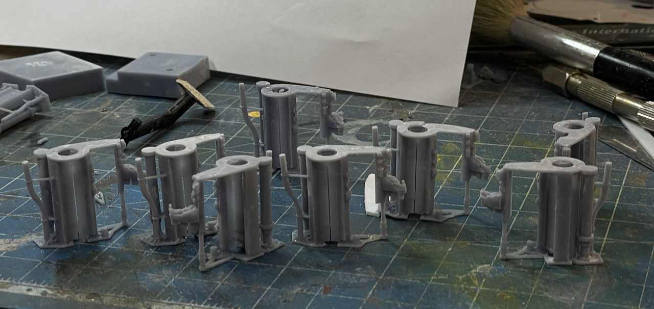
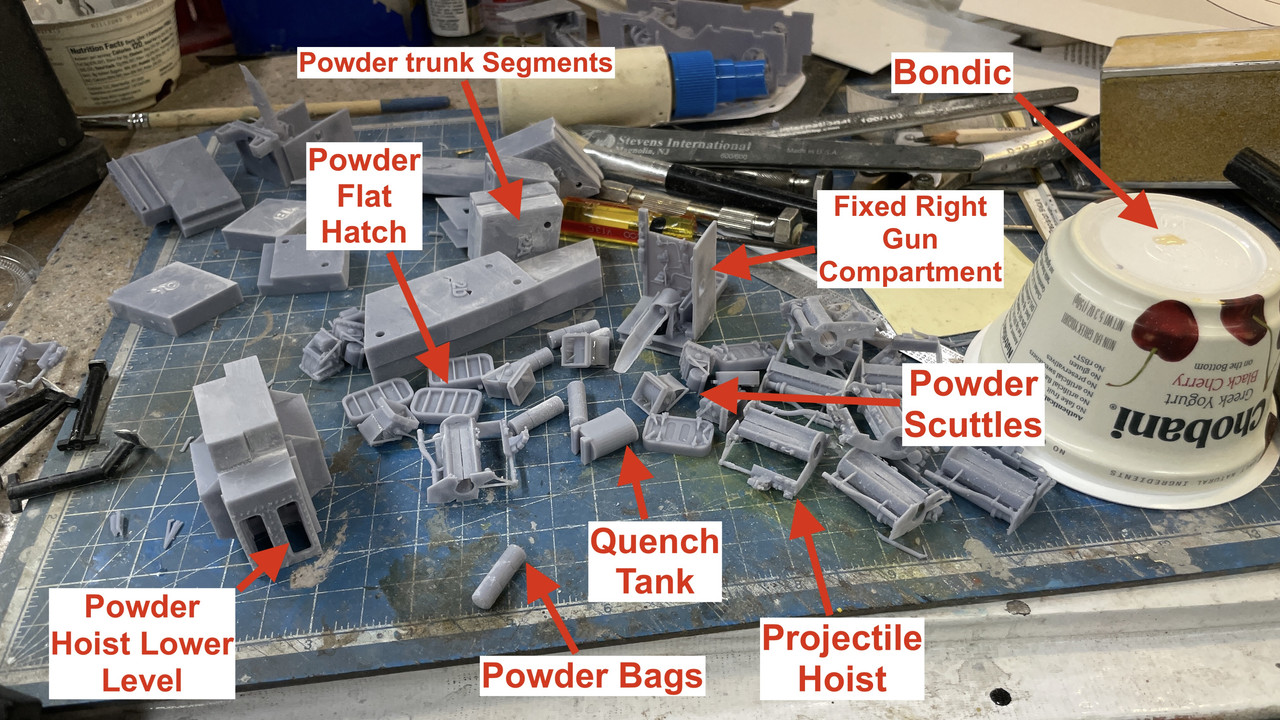
Had some strange prints today…

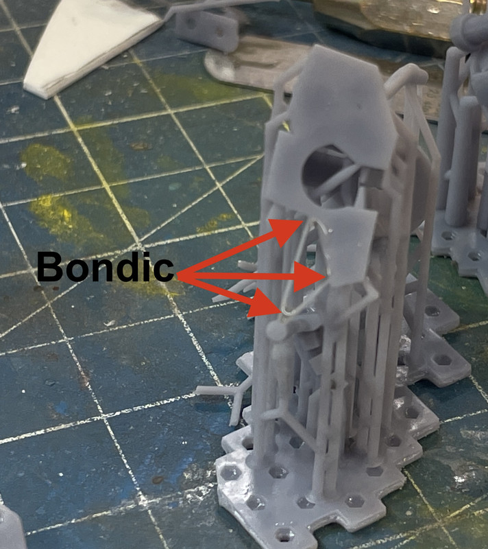
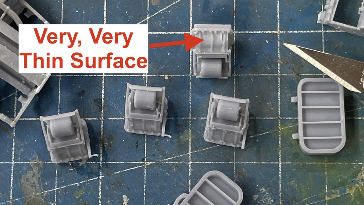
The powder cars came out… okay… but had some delamination on the flat interior surfaces of the shelf area. I decided to reinforce with Bondic, grind it off and leave it be. They were be hard to visualize and not worth the extra time to fix the drawings… yes… the delamination was a drawing problem with some inner layers causing discontinuities, nor worth the extra resin to reprint.

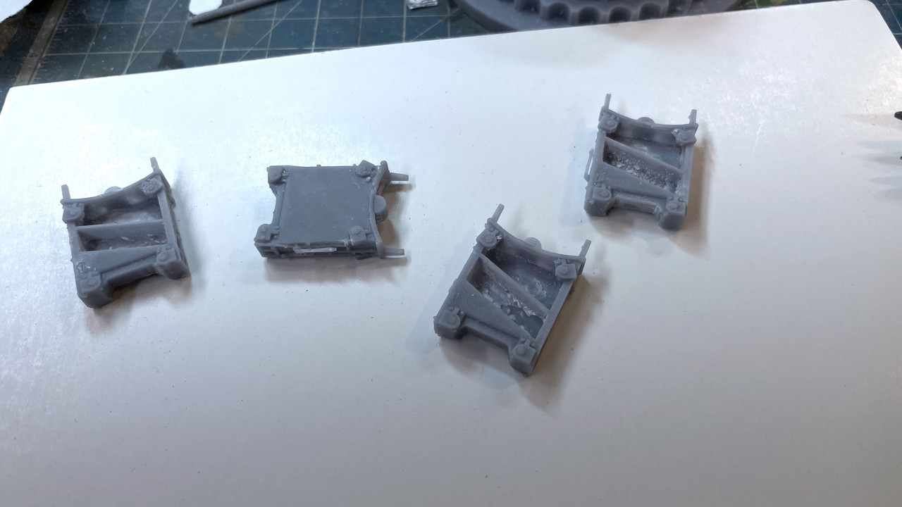
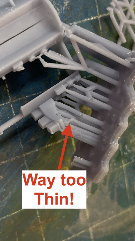
And i had the same kind of delamination on the projectile flat T2. Again, I decided to try a fix instead of spending a half hour to re-draw and then reprint. I know where the drawing defects are and it would have required starting over from scratch to create the object without the interior layers causing the problem.

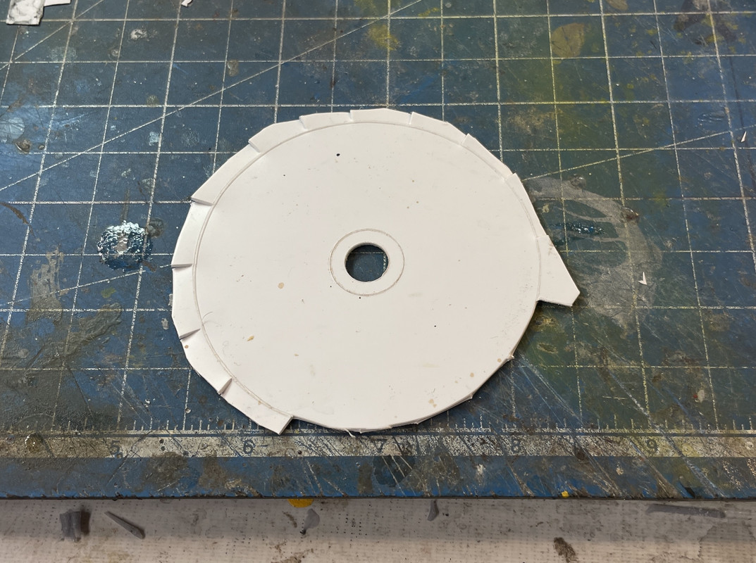
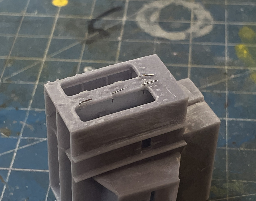
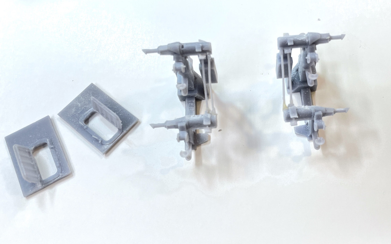
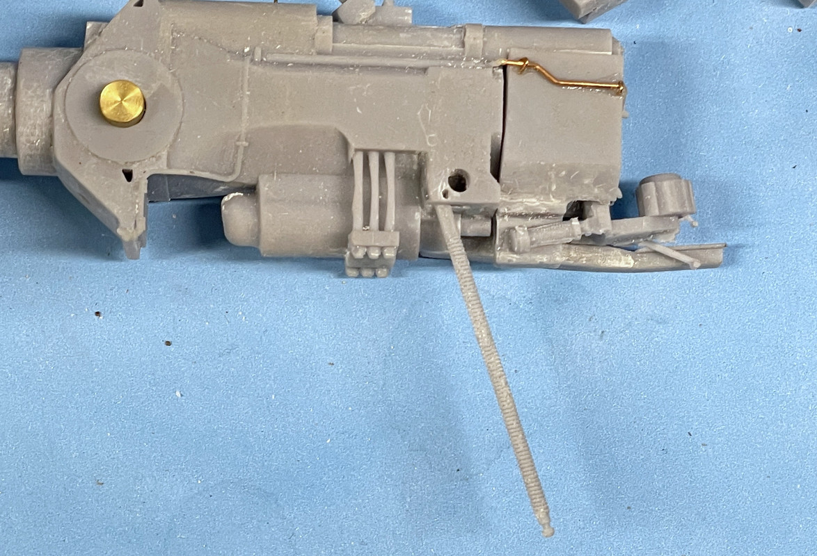
Here’s what the damaged area looked like.

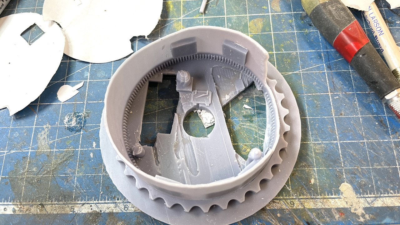
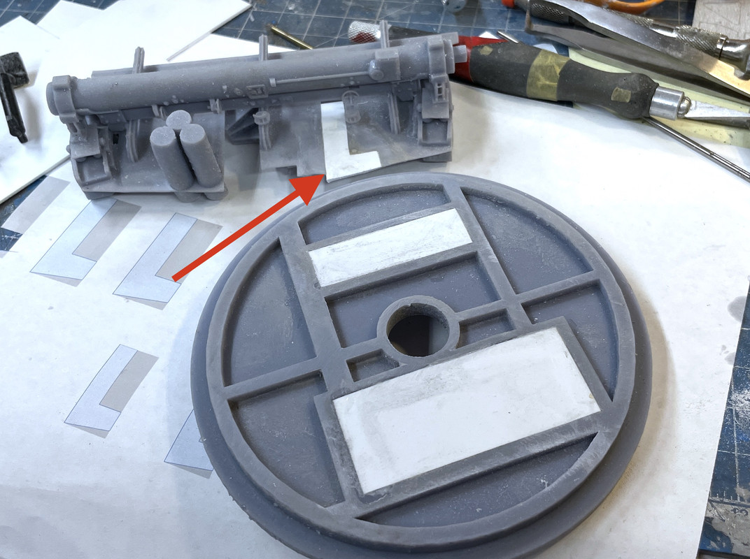
In these kinds of errors, the resin peels off like Phyllo pastery. Instead of attempting to fill all of this with something and sand it flat, I decided to build a false floor out of styrene. I also wanted to close those rectangular openings for the powder trunks. I’m installing the trunks on each deck instead of feeding them through the decks.

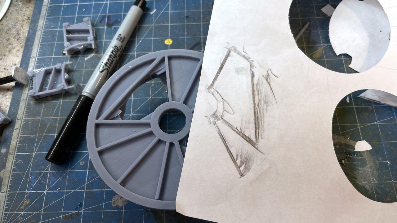
I made paper templates to fill the space on both the deck and the ceiling below.

I measured the diameter with a dividers and then measured that distance with my digital caliper, divided it in half and used the same divider to cut the paper circle. I have two dividers with one point each sharpened to a chisel edge perpendicular to the diameter. I use these for cutting all kinds of circles. It too three tries to get the diameter just right. I’m using 0.040" stock which is a tad thick, but this, like the powder cars, is going to be very difficult to visualize so the extra thickness won’t cause any trouble.

I also had to cut out holes for some of the printed appliances and that too was a bit trial and error.

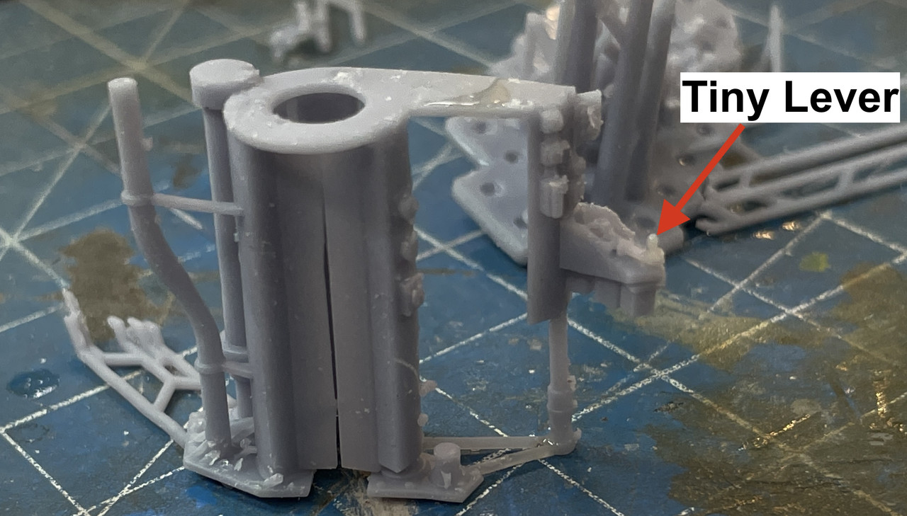
Notice in the above that one of the air cylinders is cut off. That too delaminated badly. I eventually ground it flat to the floor and will print a cylinder and install it separately.

Underneath I made paper patterns too. For these I used the rubbing method to transfer the shape below to the paper by rubbing a pencil over the edges under the paper. I cut them a bit large and trimmed to the fit.

I used the same modified dividers to repeatedly scribe the circle into the styrene and then snipped around the edges so I could break the styrene on the scribed lines. You have to take special care to break out pieces that on a curve to avoid breaking the styrene in places you don’t want to.

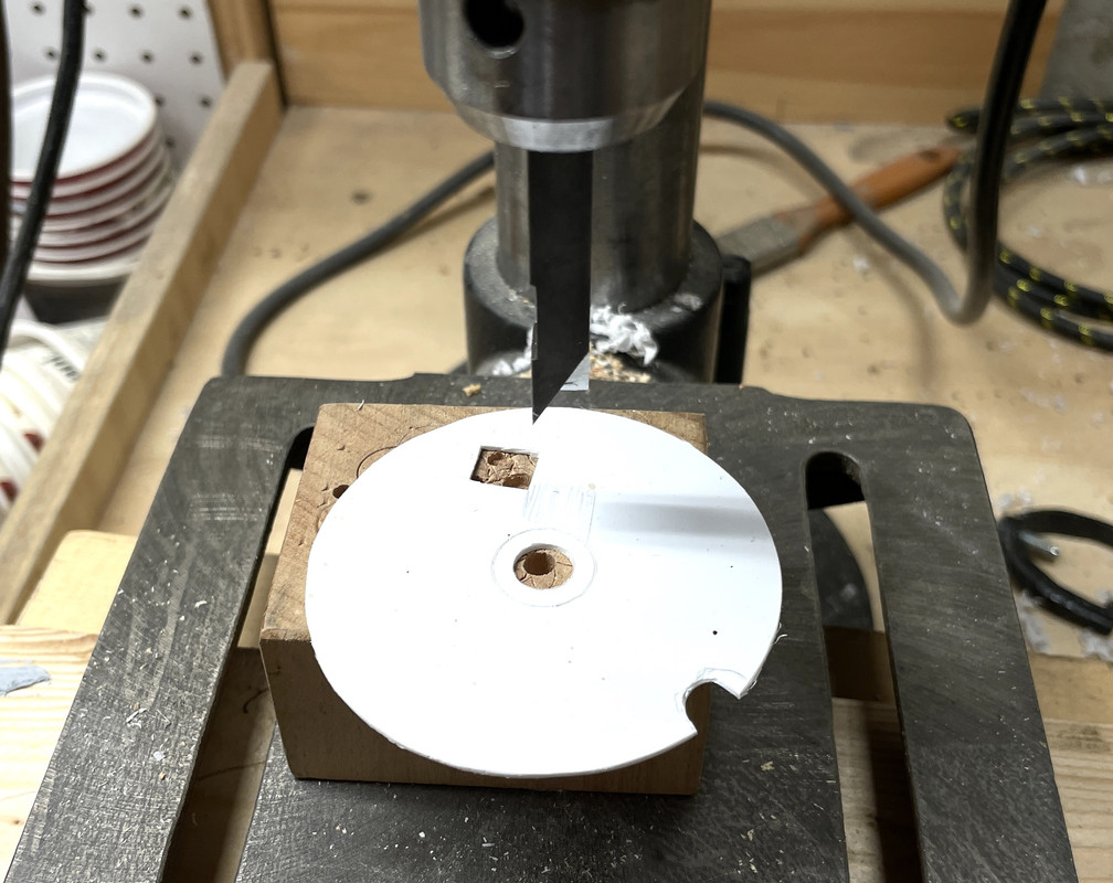
I hand sanded the edges to round it all out. And then tried the fit. It was good. I needed to make the openings for the hatch, tank and the motor sticking up through the floor. I used a special chisel I got from MicroMark years ago which cut perfect 90 degree corners. i mount it in the drill press and use solid blocking underneath so when I crank the press down hard it doesn’t force the table down too. I got the chisel specifically to cut window openings in model structures.

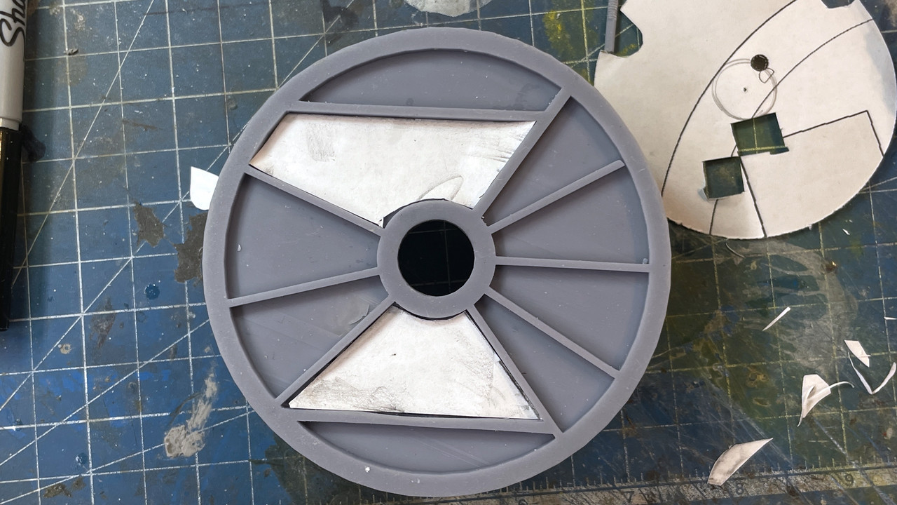
With all the cuts made the false floor fit very nicely. I did the same for the bottom pieces. I may glue these all in with 3M transfer tape adhesive. It’s a very powerful adhesive and leaves no mess. Otherwisie I may use epoxy. CA can sometimes cause styrene to decompose. Here are the paper patterns being fitted.

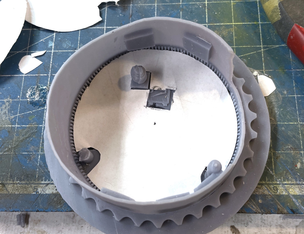
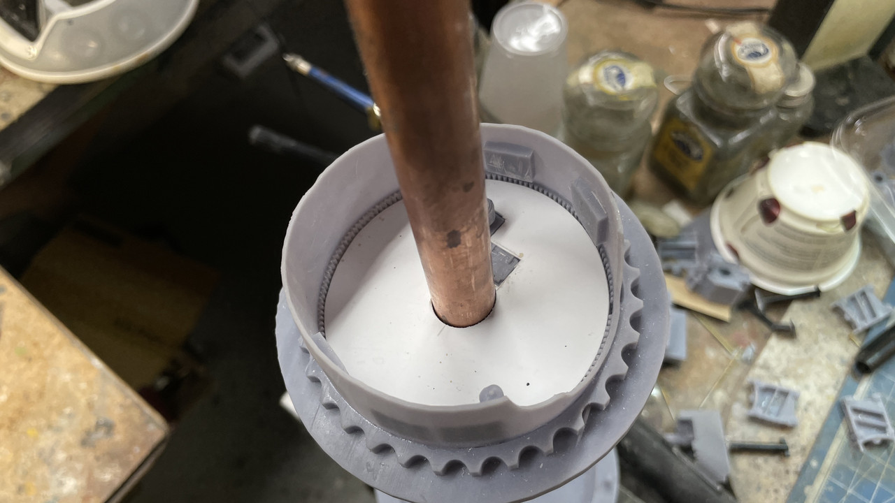
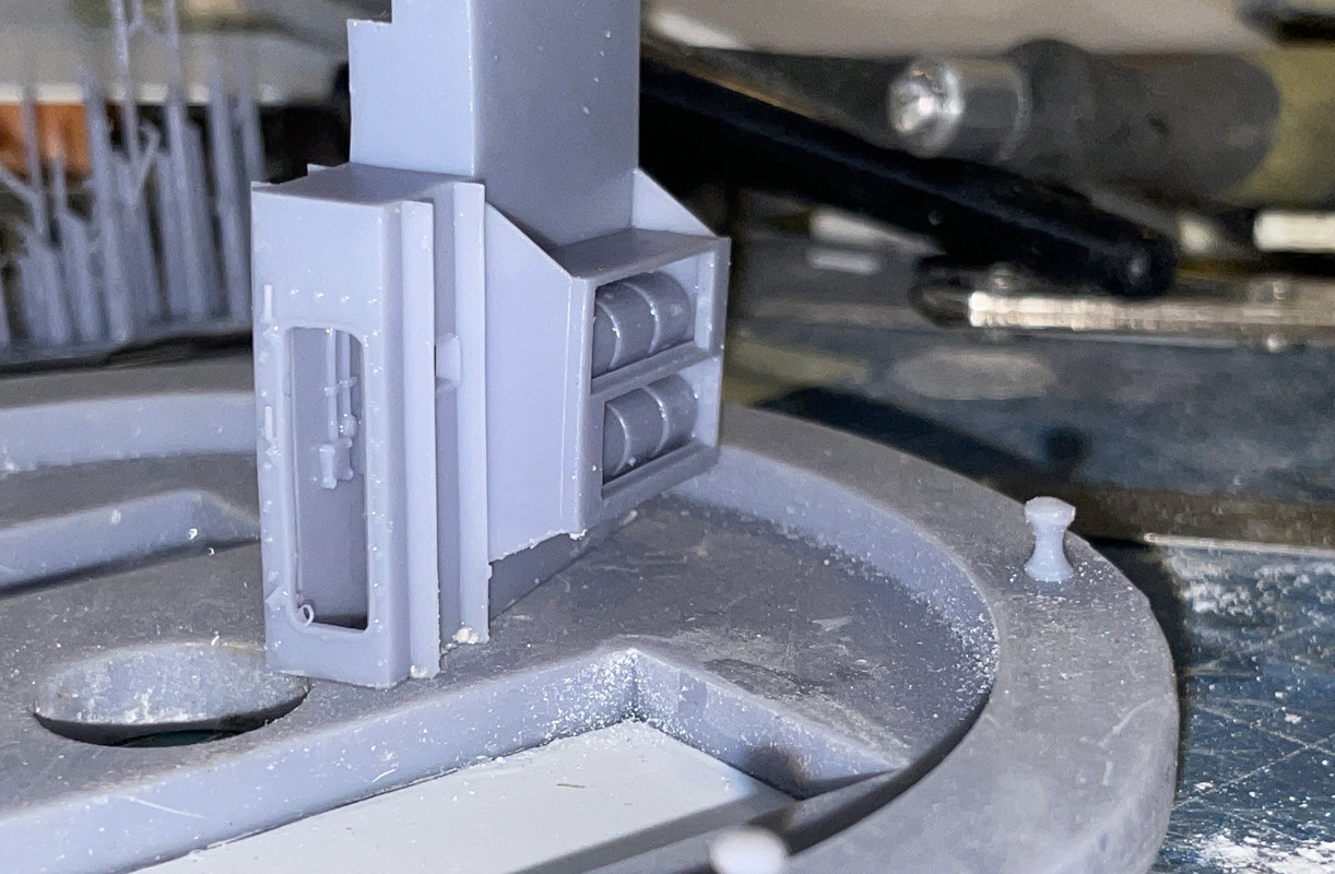
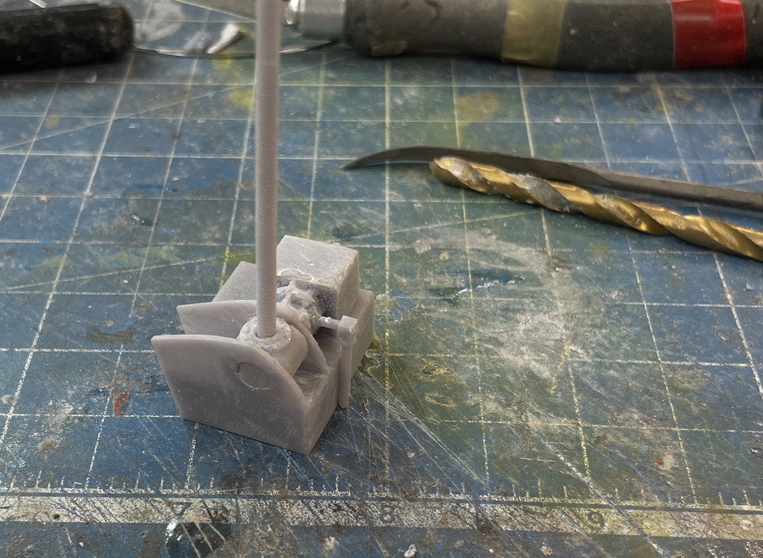
And here’s the styrene piece in place (not glued) with the center hole fitted to the central column.

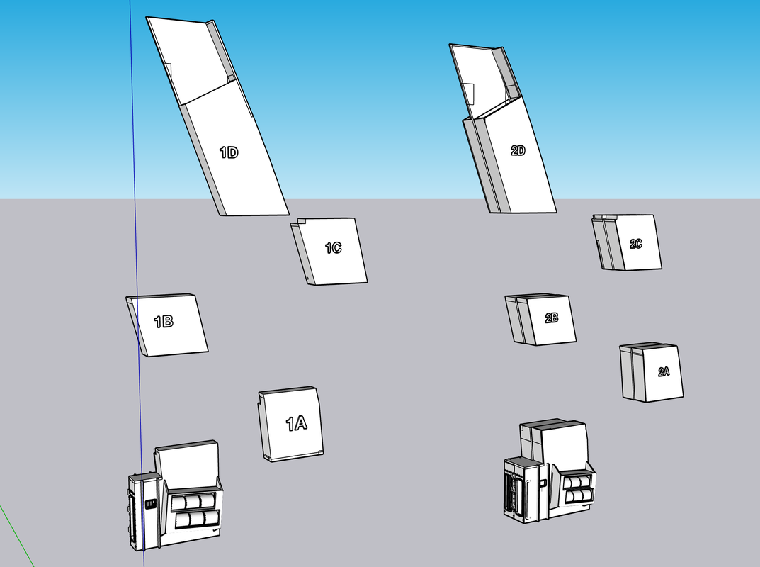
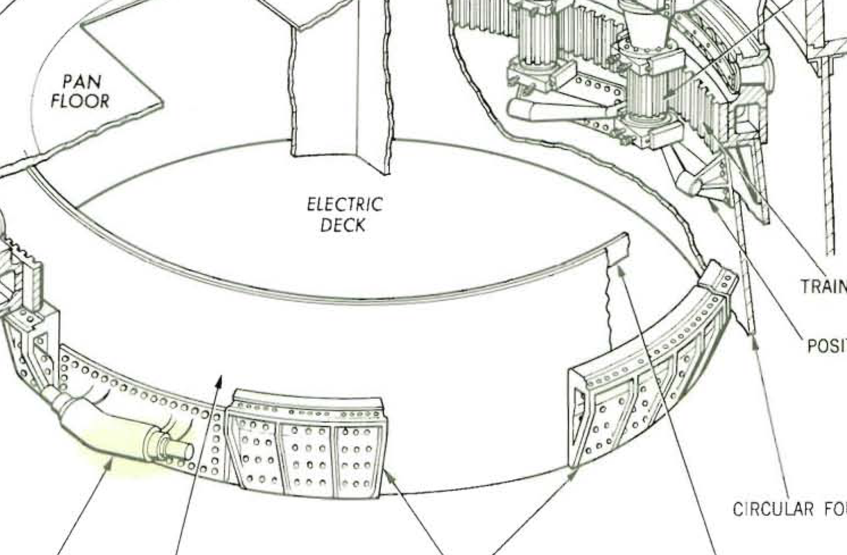
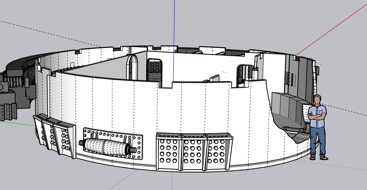
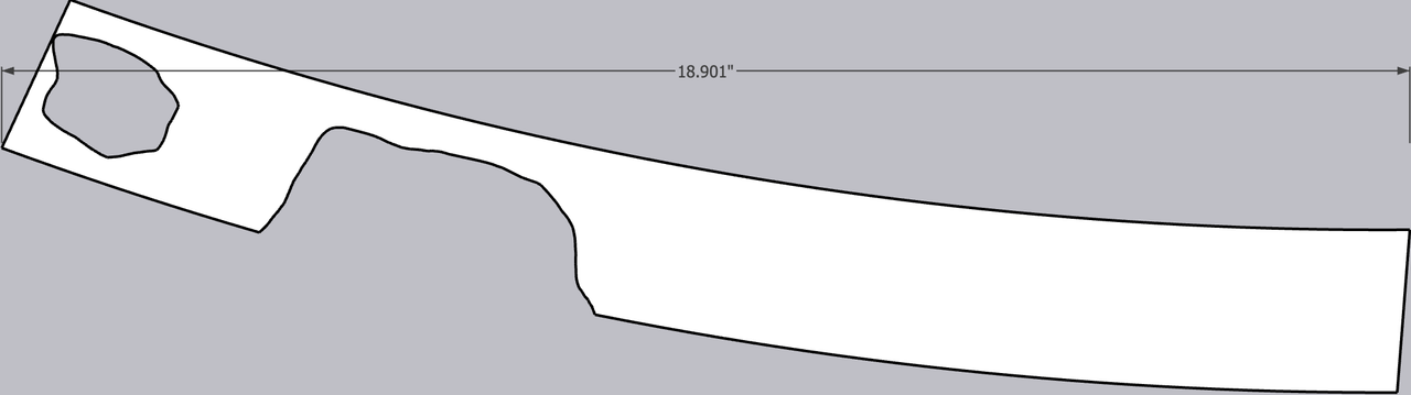
I also started working on the patterns for the shells, the first of which is the pan deck walls. My print out was the wrong developed length. I don’t know where the errors crept in as there were many places to do so. I wrapped and taped it around the actual pan deck base and got an accurate fit. This way I will be able to split the wall on the backside where I wanted to have it. I will translate this too into styrene and as i noted yesterday, I will probably put a backing plate at the junction to hold the ends together. I’m a little anxious about the upper unsupported edge. It’s not going to hold a circular shape. I may cut an upper ring… not to wide… to form and hold the upper edge. The lower outer shells will have circular decks attached to them to serve this purpose.

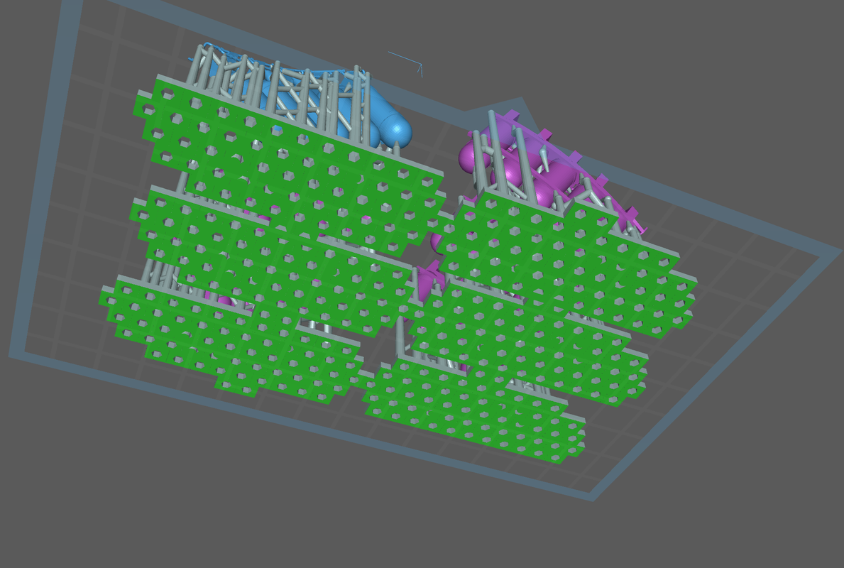
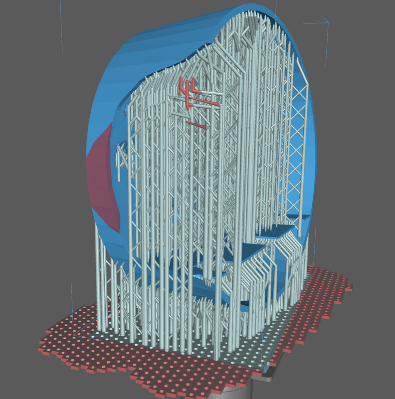
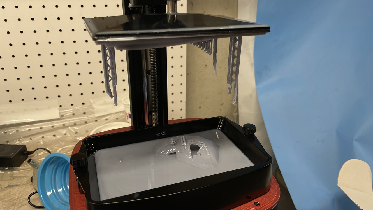
I was going to print the upper traverse parts and just started the machine. I noticed that the base was forming only on some parts of the job and were just little dots elsewhere. Those little dots were the bottom ends of supports that were starting to print on the plate without the raft. I knew immediately what was happening and killed the job after only one or two base layers were laid down. The slicer has a quirt. When you use the heavy supports the base is at level X, when you switch to light supports, the base level raises .5mm. If you’re using all light supports, the slicer knows to put the base at the plate level, but when you mix supports like I do, I have to watch where the raft is sitting. When the raft is on the plate, when viewed from below, the color is bright green. Like this:

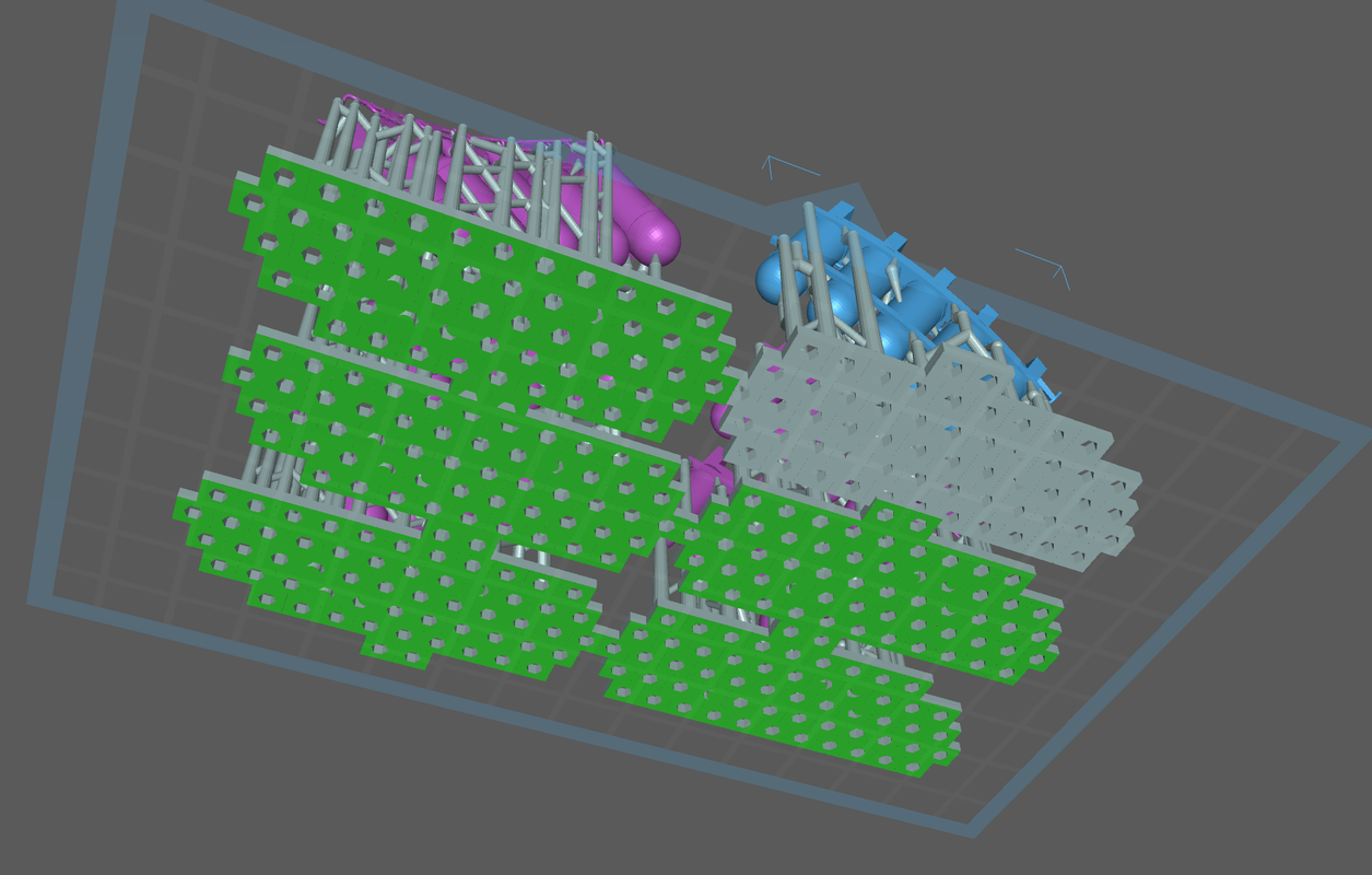
When you raise the part just .5mm this is what it looks like. That lifted part will fail. The raft will be attached to nothing and won’t even start to form.

If I know that the raft is no longer on the plate, I can adjust the z-height in the slicer and bring it back down, but in this case i missed it. I went back and fixed the job in the slicer and will reprint later. In 3D printing like a lot of other things, the details will kill you.

Boy, that burst my bubble of 3D being the perfect solution to all things scratch built. …Sigh.

Regardless, your work is top drawer and a fascinating look at the “new world” of model making and it’s tools/ techniques

Sure is! Revolutionized what I can do and even think about doing…

I have some news…

I tested positive for COVID today and I’m now relegated to quarantining upstairs. Still have my laptop. Symptoms are like flu. In other words, low-grade fever and feel like crap. They gave an antiviral, not Paxlovid, since it reacts negatively with other meds I take. They gave me Molnupiravir.

So until I’m well enough to quarantine in the shop work is hereby suspended.

Based on the suggestion to eliminate the “Takom” reference, does anyone know how to edit the thread’s title?

Never mind. I just figured it out.

Sorry 'bout the Crud–er Covid

Belive me, I’ll be glad to wait until youre better. [t$t]

Hoping for a speedy recovery Myles!